I. Introduction
New types of diseases are continuously appearing, and the number of patients with chronic diseases is also increasing. Moreover, the human lifespan is increasing because of the extension of medical services. Therefore, the number of patients who are hospitalized for a long time for treatment is also increasing.
Consequently, hospitals need to efficiently manage their patients. Automatic medication management methods to handle drug administration information and medication positions are important, and there many studies have been conducted on these methods [1ŌĆō4]. In accordance with these studies, a radio frequency identification (RFID) sensor-based system for managing the runout of a drug administered to a patient was proposed and studied [5, 6].
Previous studies on the wireless management of drug runout proposed a spherical three-axis polarized RFID tag antenna [7, 8]. In this management system, the RFID tag antenna is placed inside a feeding bag, where the antenna is exposed to the air when the drug is completely consumed. Impedance matching occurs between the tag antenna and an RFID chip to enable the wireless recognition of the information stored in the RFID and the transmission of the information to the manager. However, this management method has the drawback of antenna deterioration and drug degeneration due to the direct contact between the RFID tag antenna and the drug. Another study proposed a printed circuit board (PCB)-based tag antenna attached to the outside of a feeding bag [9]. However, the antenna is too large to be attached to the tip of the feeding bag structure, and thus information is transmitted even before the drug is completely consumed. Comparing these previously proposed systems, the drug runout management system including an RFID tag antenna attached to a drip chamber is more effective.
This article proposes an ultrahigh frequency (UHF) band (center frequency = 915 MHz) RFID tag antenna for drug runout detection that can be attached to a drip chamber. A dipole-type RFID tag antenna is downsized by using a corrugated meander line. The antenna is further downsized by using a fine meander line at the tip of the antenna where the electric current is low to make the antenna attachable to a drip chamber. A transparent cover is inserted between the antenna and the drip chamber to increase the grip force and to enable the detachment of the antenna and the viewing of the interior of the drip chamber.
II. Antenna Design
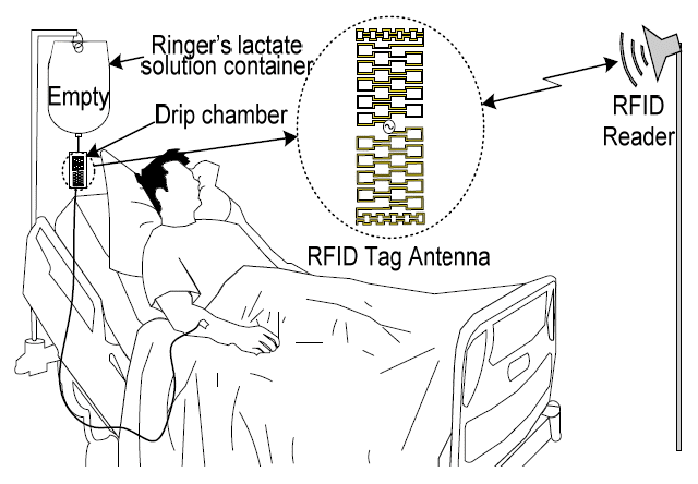
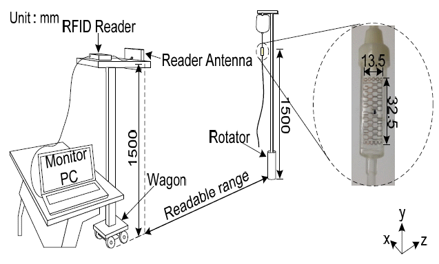
Fig. 1 shows the environment recognized by the RFID tag antenna for drug runout management through a reader. The RFID tag antenna is attached to the drip chamber of a feeding bag. When the drug remains inside the drip chamber, impedance matching does not occur between the tag antenna and the RFID chip because of the high dielectric constant of the drug, and the information in the chip is not read by the reader. Conversely, when the drug is completely consumed and the drip chamber becomes empty, the information is read by the reader as conjugate impedance matching occurs between the tag antenna and the RFID chip. Then, the information stored inside the RFID chip is recognized by the reader, enabling the RFID tag antenna to sensor the information on the runout of the drug administered to the patient. In this manner, the RFID tag antenna enables the recognition of the runout of the drug contained in the drip chamber so that the medication to the patient can be managed safely and conveniently.
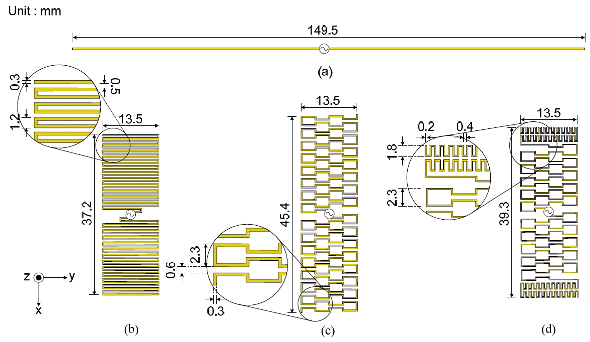
Fig. 2 sequentially shows the simulation design procedures to develop the tag antenna. As shown in Fig. 2(a), the 915 MHz basic half-wavelength dipole designed for this purpose has a length of 149.5 mm. However, the dipole length (L) should be increased for conjugate matching with the impedance of the Higgs-4 RFID chip (Higgs) used for the antenna design (Zchip = 18.42-j181.22 ╬®). As the dipole antenna is spatially limited to be attached to a drip chamber (42 mm long), the radiation element of the antenna is downsized. Firstly, as shown in Fig. 2(b), the length of the RFID tag antenna is reduced to 37.2 mm by using a fine meander line. Then, to supplement the reduction of gain due to the electric current offset in the fine meander line antenna, the antenna is further downsized by using the corrugated meander line shown in Fig. 2(c), which is a magnified image of the line intervals at the feeding point. However, the antenna length is 45.39 mm, which is still inappropriate to be attached to the drip chamber. Therefore, a fine meander line is added at the tip of the antenna where the electric current is low to decrease the length of the antenna. As a result, the antenna length is decreased to 39.3 mm, as shown in Fig. 2(d).
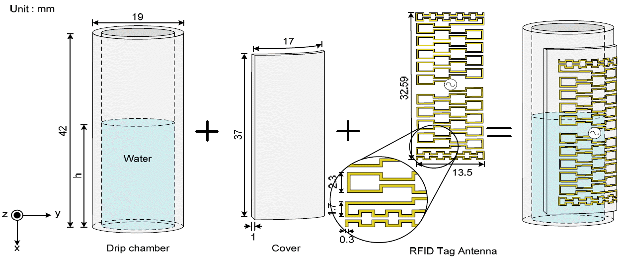
Fig. 3 shows the final structure of the antenna designed in the present study. The antenna is attached to a cylindrical polyvinyl chloride (PVC, ╔ør = 4) drip chamber 19 mm in diameter and 42 mm in height. To increase the grip force between the drip chamber and the antenna, a transparent cover, 1 mm thick and 37 mm long, is inserted between the antenna and the drip chamber. Owing to the dielectric constant of the drip chamber and the cover, the length of the antenna shown in Fig. 2(d) decreases by 14.5% from 39.3 mm to 32.59 mm in the absence of the drip chamber.
III. Simulation and Experimental Results
Fig. 4 shows the radiation pattern of the antennas shown in Fig. 2. Fig. 4(a) illustrates the radiation pattern of the basic half-wavelength dipole antenna shown in Fig. 2(a). This figure indicates that the basic half-wavelength dipole antenna has an omni-directional radiation pattern, which is a property of a dipole antenna, and a maximum gain of 1.86 dBi. Fig. 4(b) presents the radiation pattern of the fine meander line antenna shown in Fig. 2(b). The fine meander line antenna exhibits an omni-directional radiation pattern, which is a property of a basic half-wavelength dipole antenna, but the maximum gain is decreases to ŌĆō2.04 dBi because of the reduction of the antenna length and the electric current offset due to the meander line. Fig. 4(c) illustrates the radiation pattern of the corrugate meander line antenna shown in Fig. 2(c). A corrugate meander line is used to enhance the gain reduction caused by the fine meander line. The result shows that the gain increases by about 1 dBi to ŌĆō1.03 dBi in comparison with that of the fine meander line antenna. Fig. 4(d) presents the radiation pattern of the composite meander line antenna shown in Fig. 2(d). The corrugated meander line and the fine meander line are combined to further downsize the antenna, and the resultant antenna exhibits an omni-directional radiation pattern and a maximum gain of ŌłÆ1.5 dBi.
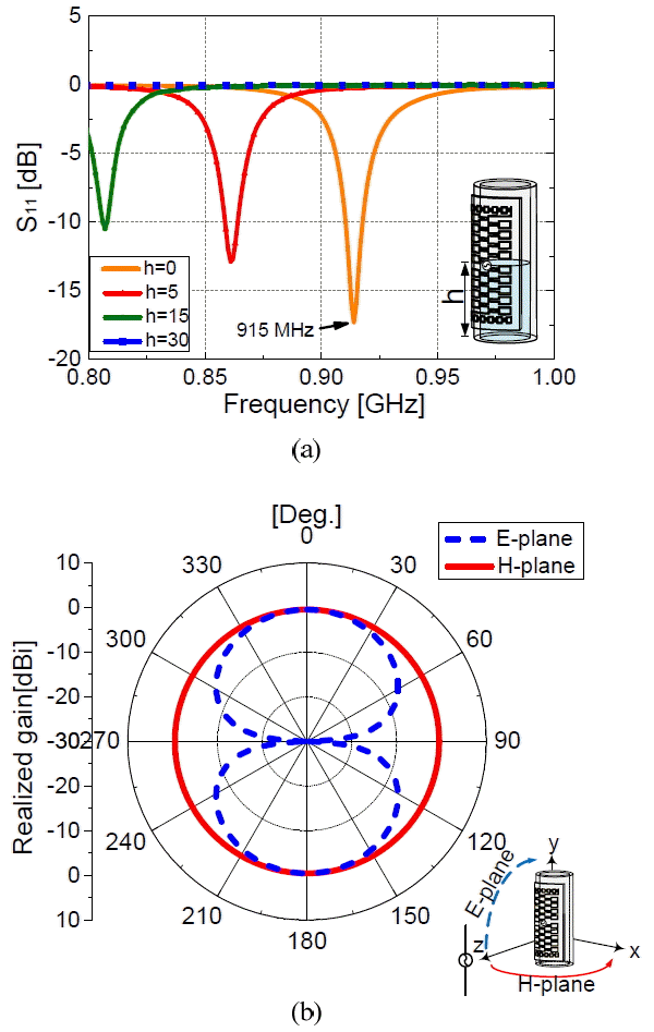
Fig. 5 illustrates the properties of the final antenna structure (Fig. 3). Fig. 5(a) shows S11 of the antenna of the final design depending on the height (h) of the drug inside the drip chamber. As the drug height (h) decreases, the resonance frequency shifts toward the center frequency of 915 MHz. When the drug height become 0, impedance matching occurs at 915 MHz with S11 of ŌłÆ17.4 dB (bandwidth = 7.3 MHz, 0.79%), indicating that the RFID tag normally functions as a sensor only when the drug is completely consumed. Fig. 5(b) indicates that the antenna has an omni-directional radiation pattern with a gain of ŌłÆ0.46 dBi. As the properties of the tag antenna are not changed by the attachment of the RFID tag antenna to the drip chamber, a patient medication management system may be appropriately designed by using the RFID tag antenna developed in the present study.
Table 1 shows the results of the simulation of the properties of the antennas designed in the study.
Fig. 6 illustrates the measurement setup for the property analysis of the completed antenna structure fabricated. The RFID reader is the Air-9000 Model of Alien with an intensity of 4 W. The sensing distance is measured with the RFID reader by attaching the antenna to the drip chamber and distancing it 1,500 mm from the ground. The antenna structure is fabricated by etching copper tape, and attached to a double-sided tape so that the structure can be detached and re-attached. The size of the fabricated antenna is 32.59 mm ├Ś 13.5 mm, which is equal to the simulated antenna.
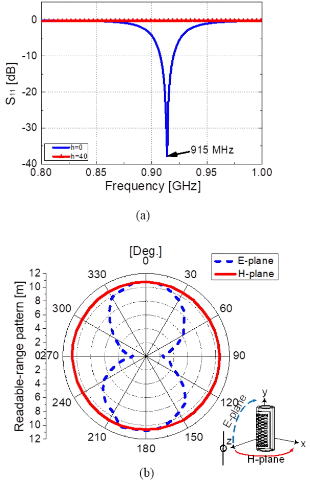
Fig. 7 exhibits the measured properties of the fabricated antenna. Fig. 7(a) shows that S11 at 915 MHz is ŌłÆ37.79 dB (bandwidth = 12 MHz, 1.31%) when the drip chamber is empty. By contrast, when the water height (water is used instead of a drug) is 40 mm in the drip chamber, the reader is unable to recognize the RFID tag because no impedance matching occurs at 915 MHz. The EŽå component on the xz-plane shows an omni-directional read range of 10.65 m on average, and the E╬Ė component on the yz-plane presents an ŌĆ£8ŌĆØ-shaped read range, which indicates that the half-wavelength dipole property is maintained.
IV. Conclusion
This article proposes a UHF-band RFID tag antenna for drug runout detection that can be attached to a drip chamber. The function of the antenna is based on the change in the impedance matching depending on the presence of a drug inside a drip chamber. The antenna is downsized by using a meander line to enable impedance matching between an RFID chip (Zchip = 18.43-j181.22 ╬®) and the tag antenna and to shorten the antenna. In addition, the gain is increased by 0.54 dB through the combination of a fine meander line and a corrugate meander line. The dimensions of the completed designed antenna are 32.59 mm (height) and 13.5 mm (width). The measurement of the sensing distance of the designed antenna shows that the antenna has an average omni-directional read range of 10.65 m on a horizontal plane. This result verifies that the RFID tag antenna proposed in this article can be attached to a drip chamber to function as a drug runout sensor, which transmits information from a sickroom through an RFID reader.


