I. Introduction
In the air-to-air mode of airborne pulse-Doppler radar, medium pulse repetition frequency (MPRF) waveforms can detect all aspect targets and precisely measure the range and Doppler of the targets at one time. However, despite the use of optimal PRF sets, the detection range performance of MPRF waveforms is degraded in low-altitude platforms because of the effect of sidelobe clutter [1, 2]. In MPRF waveforms, clutter of all Doppler and ranges is folded into one PRF Doppler and one pulse repetition interval range. Folded mainlobe clutter is found in a limited Doppler region, whereas folded sidelobe clutter is found in almost all Doppler regions. In low-altitude platforms, the folded sidelobe clutter of high power affects almost all Doppler and range regions. In other words, when the platform altitude is low (i.e., when the power of the sidelobe clutter is high), sidelobe clutter disturbs the target detection and cause the critical degradation of the detection range performance of MPRF waveforms. Even when the detection range performance of an MPRF waveform is 80 km without any effects of sidelobe clutter, the performance of the MPRF waveform can be degraded to 40 km and below with sidelobe clutter if the platform altitude is below 2 km. The degree of performance degradation is determined by the platform altitude and sidelobe levels of the antenna radiation pattern. Ordinary aircraft radars have sum (Ōłæ), diff. azimuth (╬öa), diff. elevation (╬öe), and guard (╬ø) receiving the channels of an antenna. Therefore, sigma-delta spatiotemporal adaptive processing (STAP) can be used in ordinary aircraft radars. Sigma-delta STAP was used in the mainlobe clutter reduction to detect the ground moving targets of low velocity in the air-to-ground mode of aircraft radars [3]. This study proposes the sidelobe clutter reduction method using sigma-delta STAP. In the air-to-air mode of airborne radars that use MPRF waveforms, this sidelobe clutter reduction method improves the detection range performance, which has been degraded in the low-altitude platform. In terms of the sidelobe clutter-reduction performance and the effectiveness of increasing the detection range, the proposed method is simulated and tested using simulated data. Our method of removing sidelobe clutter is based on the same joint domain localized (JDL) method as in [3]. However, the application of algorithms for sidelobe clutter removal and the method of setting related algorithm parameters in the air-to-air environment differ from the method of removing mainlobe clutter in the air-to-ground environment of [3]. Therefore, our proposed method is also compared with the method of [3] in terms of the sidelobe-clutter-removal performance through a simulation.
II. Sigma-Delta STAP for Sidelobe Clutter Reduction
In this study, airborne radars have Ōłæ, ╬öa, ╬öe, and ╬ø receiving the channels of an antenna, and they perform the detection of air-to-air targets with these four channels. Using the sigma and delta channels to apply the STAP is an appropriate way to remove sidelobe clutter based on the STAP without configuring additional receiving channels of an antenna in the structure of antenna channels of most fighter radars. The sigma-delta STAP of this paper is similar to the JDL [4] method and is a special case of the JDL. The JDL method suppresses interference signals using the signals within the localized processing region (LPR) in the post-Doppler/beamspace domains.
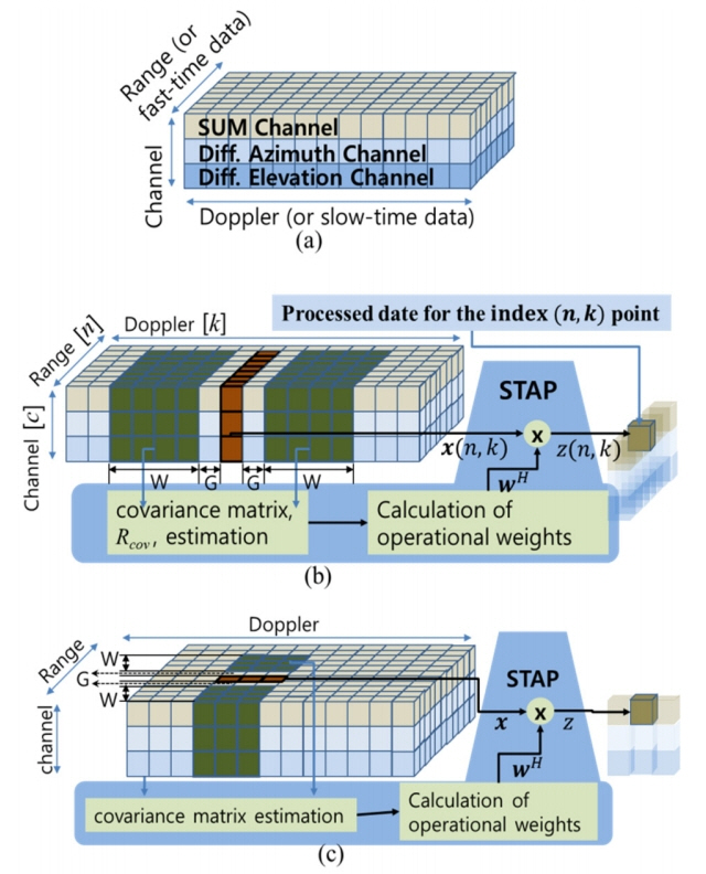
A data cube, which is formed for the sigma-delta STAP, is described in Fig. 1(a). The LPR for the sigma-delta STAP in this study is illustrated in Fig. 1(b), which represents the training data collection and filter weight calculations for the STAP application to remove the sidelobe clutter. In Fig. 1(b), data x(n, k), which is processed by STAP for the elimination of the sidelobe clutter of the index (n, k) point, is expressed as follows:
In xc,n(k) of Eq. (1)c is the index of antenna receiver channel, n is the range index, and k is the Doppler channel index. The training data X for the STAP processing of data x(n, k) are as expressed follows:
In Eq. (2)A = W + G, B = G + 1, W is the number of range cells that takes the training data around the data x(n, k), as shown in Fig. 1(b), and G is the size of the guard cells that prevent the collection of training data that have information on the data x(n, k) and is set to take only the interference signal as training data. We set N = 3, W = 20, and G = 1 in the simulation in this study. The collection of training data for the elimination of the sidelobe clutter is different from the case of eliminating the mainlobe clutter. We can compare the collections of training data of this study with the collections of training data to eliminate the mainlobe clutter in [3]. Fig. 1(c) represents the training data collection and filter weights calculations for the STAP application proposed in [3] to remove the mainlobe clutter. The main difference is that the positions of the guard cells are represented as Doppler channel indexes in the proposed method, whereas in [3], the guard cells are represented as range indexes. In other words, we collect training data on the sidelobe clutter in the Doppler direction to remove the sidelobe clutter of the (n, k) position. Conversely, in [3], training data are collected in the range direction to remove the mainlobe clutter. In addition, there are differences not only in the direction in which the guard cell is applied but also in the direction in which the reference cell is applied and the number of reference cells. This difference in the collection of training data shows that the effect of removing the sidelobe clutter is more prominent than that of the mainlobe clutter.
The covariance matrix from the training data is expressed as follows:
In Eq. (3)XH is the Hermitian transpose of X, I is the identity matrix, ╬╗I is the diagonal loading term, and ╬╗ = 0.01 in our simulation (╬╗ should be set appropriately according to noise level). The calculation for STAP is as follows:
III. Simulation and Test
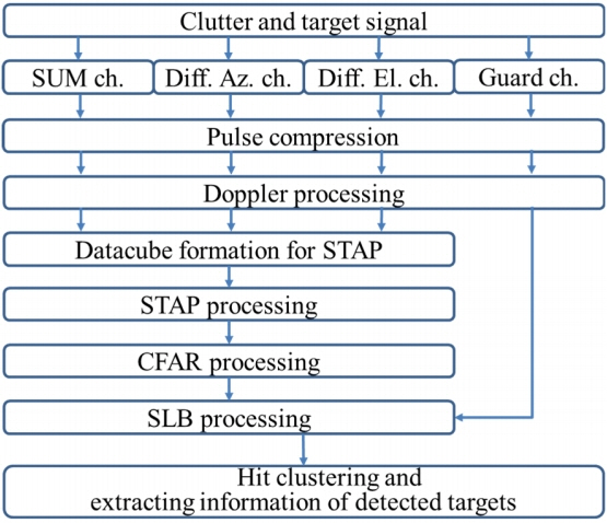
In this section, we perform a simulation to test the performance of the proposed sidelobe clutter reduction method. The scenario and system parameters used in our simulation are represented in Table 1. Using the values in Table 1 and a simulated antenna pattern, we generate simulated clutter and target signals [3]. In the simulated antenna pattern of the sum channel, the power ratio of the sidelobe to the mainlobe of the antenna beam is ŌłÆ60 dB. When generating the simulated clutter signals, we use the constant gamma model as a ground clutter reflectivity model. The constant gamma item in Table 1 represents the gamma value used in the constant gamma model of this simulation. To verify the effect of increasing the detection range after removing the sidelobe clutter by our proposed method, the signal processing to detect air-to-air targets for the simulated clutter and target signals is performed, as shown in Fig. 2. In our proposed method, we set N = 3, W = 20, and G = 1 (see Fig. 1(b)). The parameter value, which is set for the method in Fig. 1(c), is set to the value suggested in [3].
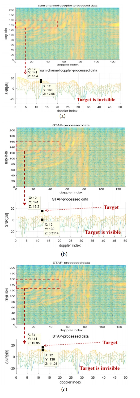
We compare the results of performing the signal processing of detecting air-to-air targets without removing the sidelobe clutter. The results of removing the sidelobe clutter using the method in [3] (Fig. 1(c)) are compared with those of removing the sidelobe clutter by the method presented in this paper. Fig. 3 compares the powers of the clutter of the range/Doppler (RD) maps with the results of Doppler processing before and after removing the sidelobe clutter. Fig. 3(a) shows the clutter before removing the sidelobe clutter, and Fig. 3(b) illustrates the clutter after removing the sidelobe clutter using the proposed method. Fig. 3(c) shows the clutter after removing the sidelobe clutter using the method in [3] (Fig. 1(c)). The dotted square areas shown in each RD map of Fig. 3 are enlarged and displayed at the bottom of each RD map. Before removing the sidelobe clutter, a target is buried in the clutter in the dotted square area, and the target is invisible (Fig. 3(a)). After removing the sidelobe clutter using the proposed method, the target appears in the area (Fig. 3(b)) and has a detectable signal-to-interference and noise ratio (SINR). Note that the detection performance of the CFAR processing in Fig. 2 is determined by the SINR around the targets. In Fig. 3(a), the signal-to-noise ratio (SNR) of the target is 16.4 dB, the clutter-to-noise ratio (CNR) around the target is 12.55 dB, and the SINR around the target is 3.85 dB. In Fig. 3(b), SNR of the target is 15.2 dB, the CNR around the target is 0.31 dB, and the SINR around the target is 14.89 dB. In Fig. 3(c), SNR of the target is 15.95 dB, CNR around the target is about 11.03 dB, and SINR around the target is about 4.92 dB. Fig. 3(a) and (b) show the 11.04 dB (= 14.89ŌĆō3.85 dB)
SINR improvement using the proposed method. The CNR of the clutter around the target decreases to 0.31 dB from 12.55 dB after the sidelobe clutter is removed (sidelobe clutter reduction performance is 12 dB or more). Conversely, Fig. 3(a) and (c) show only about 1.07 dB (= 4.92ŌĆō3.85dB) of SINR improvement using the method in [3], and CNR around the target decreases to only 11.03 dB from 12.55 dB. After removing the sidelobe clutter using the method in [3], the target remains buried in the clutter in the dotted square area, thus making it invisible (Fig. 3(c)). As shown in Fig. 3, the sidelobe clutter is not properly removed by the method in [3] and sufficient SINR is not secured.
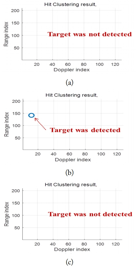
Fig. 4(a) shows the hit clustering result of the signal processing of detecting targets without removing the sidelobe clutter. Fig. 4(b) presents the result of detecting targets with removing the sidelobe clutter using the proposed method. Fig. 4(c) shows the result of detecting targets with removing the sidelobe clutter using the method in [3].
The target range of 73 km, which is not detected because of the sidelobe clutter in the platform altitude of 3 km, is detected by removing the sidelobe clutter using the proposed method.
IV. Conclusion
To counter the degradation of the detection-range performance of air-to-air targets due to sidelobe clutter at low altitudes of airborne radars in MPRF waveforms, we suggested a method of removing the sidelobe clutter using sigma-delta STAP. The sidelobe clutter reduction performance of the proposed method was verified at 12 dB through simulations. The effectiveness of increasing the detection range was verified through signal processing simulations that detect targets.