I. Introduction
Wireless power transmission (WPT) technologies have been increasingly employed in a variety of applications such as medical devices [1], mobile phones [2], and vehicle systems [3]. Microwave power transmission (MPT), which is one of the WPT technologies, has the advantage of being able to transmit power at middle and long distances [4]. This MPT method uses array antennas for both transmitting and receiving systems, and microstrip patch antennas are generally employed due to their high directivity with low-profile characteristics [5, 6]. Many previous studies, such as optimization of the array configuration, efficient feed network design, and techniques using retrodirective beamforming, have focused on the improving transmission efficiency [7ŌĆō10]. However, these array antennas still exhibit the performance degradation caused by the mutual coupling between adjacent elements. Moreover, in-depth studies on the optimization of the element number in a limited small space is not sufficient yet.
In this paper, we propose the design of a small aperture array antenna for an MPT system, which is advantageous for high power transmission with a small sized array aperture. The problem of the increased mutual coupling between array elements is examined when more elements are used for a high input power of the array. We employ a 64-element array in a small space of 12 cm ├Ś 12 cm, and thus the input power of each element which causes the high mutual coupling and the low efficiency of the RF circuit can be minimized. The proposed array element is composed of a square loop printed on a high-dielectric substrate and an extended cavity structure enclosing the substrate. The high-dielectric substrate and loop resonator are used for miniaturization to mount multiple elements in a limited space, which enables to maximize the transmission power. The mutual coupling between adjacent elements is reduced by inserting an extended cavity structure, and the input power per each element is lowered to enhance the efficiency of the RF circuit by increasing the number of array elements. We derive the optimal number of elements in a limited space, taking into account the input power on each element, fabrication cost, and aperture efficiency of the system. To verify the performance of the optimized array for the MPT system, a 2 ├Ś 2 downscaled array antenna is fabricated and measured. The results demonstrate that the proposed antenna with the extended cavity structure is suitable for use as an MPT array element for high power transmission with a small sized aperture.
II. Proposed Array Antenna Element
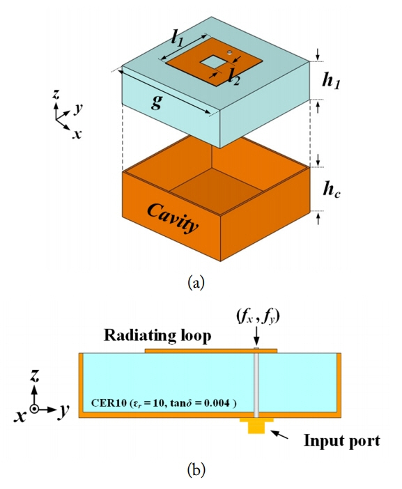
Fig. 1 shows the geometry of the proposed MPT antenna element. The element consists of a rectangular loop and an extended cavity structure printed on a high-dielectric ceramic substrate (╔ør = 10, tan╬┤ = 0.004) with a thickness of h1, which is equal to the thickness of the cavity (hc). The square loop is designed with the external and internal diameters of l1 and l2, respectively, and it is directly connected to the feed structure, which is denoted as (fx, fy). The extended cavity structure resides above the ground plane and surrounds the entire lateral surfaces of the ceramic substrate. This proposed structure can help to decrease the mutual coupling between adjacent elements by reducing the leakage field from the antenna substrate. The detailed design parameters are optimized by a genetic algorithm [11] and listed in Table 1.
The antenna characteristics of a fabricated element, such as the bore-sight gain and reflection coefficient, are measured in a full anechoic chamber. The measured and simulated bore-sight gains of the element are shown in Fig. 2. The dashed line indicates the simulated values, and the measured data are specified by the ŌĆ£Ō¢ĪŌĆØ symbol.
Both results show a good agreement with the simulated value of 3.3 dBi at 5.8 GHz and 3.6 dBi of the measured value. The low gain of the small aperture element is resolved by increasing the number of small aperture elements (64-element in this work). For a given total array space of 12 cm ├Ś 12 cm, as we increase the number of elements, the array gain approaches the ideal gain considering the array aperture size.
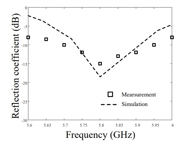
Fig. 3 presents the simulated reflection coefficient compared with the measured data. The simulated and measured values are less than ŌłÆ10 dB from 5.73 GHz to 5.9 GHz, and the values are ŌłÆ18.5 dB and ŌłÆ14.9 dB at 5.8 GHz, respectively. The slight difference between the simulation and measurement at 5.9 GHz is due to the fabrication tolerance, such as effective dielectric permittivity, and the loss tangent of the antenna substrate. The high-Q behavior of the antenna element with a narrow bandwidth may be appropriate when a single antenna is used for a WPT system. However, the performance of the high-Q antenna can be easily degraded by an unwanted frequency shift when the elements are closely arranged for a small aperture array. This performance degradation can be minimized by using the antenna element with an appropriate Q value for a WPT system.
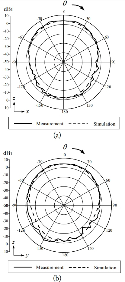
Fig. 4 shows the radiation patterns of the antenna in the zx-plane and zy-plane at 5.8 GHz. The measured half-power beamwidths (HPBWs) in the zx- and zy-planes are 120┬░ and 115┬░, respectively. As can be seen, the proposed antenna element does not have any serious pattern distortion in the upper hemisphere.
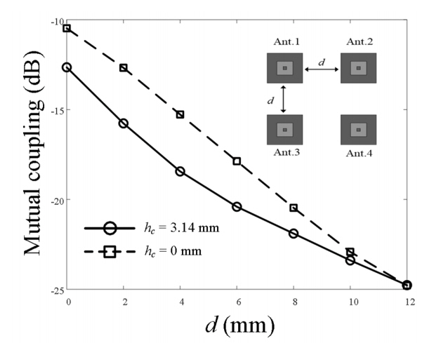
To confirm the effectiveness of the proposed extended cavity structure on the isolation characteristic, we analyze the average mutual coupling of the 4-element planar array according to the distance of the physical separation (d) from 0 mm to 12 mm as presented in Fig. 5. The antennas with and without the extended cavity structure have an identical value of ŌłÆ25 dB at d = 12 mm. The mutual coupling of the proposed antenna increases up to ŌłÆ12.5 dB as d becomes zero, whereas that of the antenna without the extended cavity goes up to ŌłÆ10.4 dB. The difference in the mutual coupling strength of the antenna with and without the extended cavity is greater than 2 dB, indicating that the proposed structure can enhance the isolation characteristic.
III. Proposed Array Antenna
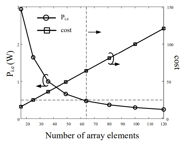
The proposed element is now applied to the transmission array antenna for an MPT system. We limit the aperture size of the array to 12 cm to verify the feasibility of the proposed antenna with a very small aperture size. The received power is calculated using the Friis equation [12]. We assume a scenario in which the receive antenna is a 2 ├Ś 2 array with a gain of 7.6 dBi, and a received power of 0.2 W is required at a distance of 1 m. The optimal number of elements is derived by considering the input power for each element, fabrication cost, and aperture efficiency of the array. The input power for each element is restricted to under 0.5 W considering the efficiency and the manufacturing cost of the RF circuits.
Fig. 6 provides a parametric study of the input power for each element (Pi.e) to satisfy the received power of 0.2 W. The cost is the approximated total fabrication cost of the array antenna when normalizing the manufacturing cost of one antenna element to cost = 1. The element number is required to be 64 or more to reduce the input power per element to less than 0.5 W, which satisfies the scenario.
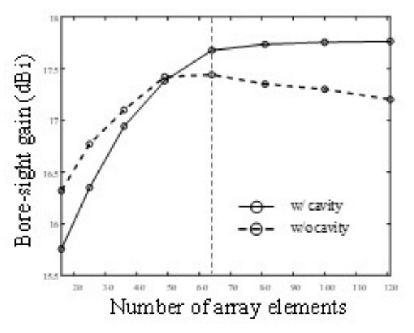
Fig. 7 presents the comparison of the bore-sight gain with and without the extended cavity structure according to the number of array elements. The feed structure of the power divider is not considered because we assume that there is no insertion loss of the power divider. The reason for examining the performance from a small element number to a large number of elements is to find the optimum number of array elements for maximizing the array performance in a limited space of 12 cm ├Ś 12 cm. The gain of the array according to the number of array elements converges to about 17.7 dBi when the array number becomes 64 or more. The reason for the convergence is that the aperture size of the array is limited to 12 cm ├Ś 12 cm. The maximum gain is determined by the total aperture size and aperture efficiency, and the ideal gain achievable from the aperture size is about 18.3 dBi with an efficiency of 1. We also compare the gain of the array without an extended cavity structure to confirm the performance enhancement by using the proposed array with an extended cavity structure. The array without an extended cavity structure has a reduced gain of 17.2 dBi when the array number becomes 121 due to the strong mutual coupling.
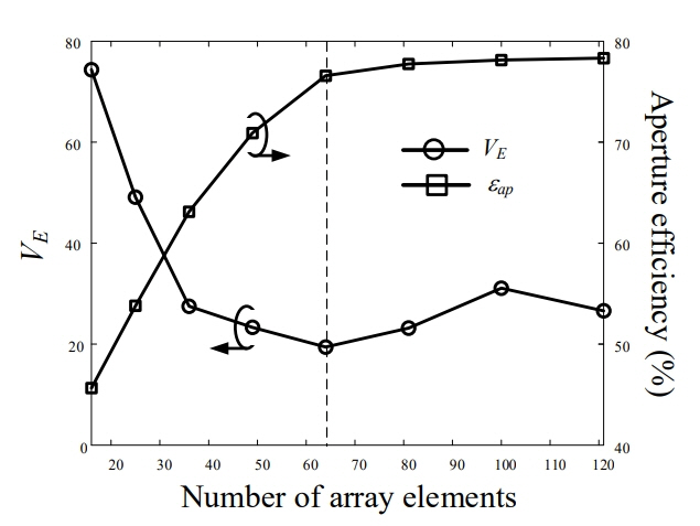
To verify the performance of the proposed optimal number of elements, we analyze the aperture efficiency and electric surface current variance as shown in Fig. 8. The aperture efficiency is proportional to the antenna gain and converges to about 77% when the number of array elements is 64. The variance for the amplitude of the electric surface current near the aperture (ŌłÆ600 mm Ōēż x, y Ōēż 600 mm, z = 5 mm) is examined using the Eq. (1). The variance is minimized to 20 when the aperture efficiency converges to its maximum value.
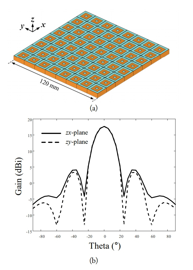
Fig. 9(a) presents the geometry of the proposed 64-element array with an aperture size of 12 cm ├Ś 12 cm, and the simulated gains of the zx- and zy-planes are shown in Fig. 9(b). The proposed each antenna element has a radiator with dimensions of 6.8 mm ├Ś 6.8 mm, and thus the antenna size is 15 mm ├Ś 15 mm including the extended cavity structure. The feed to feed distances are set to be 15 mm, and the total array aperture size is 120 mm ├Ś 120 mm with the 8 ├Ś 8 array configuration. Therefore, a size reduction of about 0.1 is obtained compared with a conventional 0.5╬╗ distance array structure (413 mm ├Ś 413 mm). The simulated bore-sight gain (╬Ė = 0┬░) is 17.68 dBi at 5.8 GHz, and the HPBW in the zx- and zy-planes are 21.28┬░ and 21.56┬░, respectively. The proposed array has a 5.6% transmission efficiency at a distance of 1 m when the proposed array is applied to both transmitting and receiving antennas. The transmission efficiency of 5.6% is the antenna to antenna transmission efficiency calculated using the Friis equation. In the efficiency calculation method, we assume that there is no insertion loss in the power divider and the other RF circuits. However, the efficiency using the Friis equation may not be accurate since the analysis distance is slightly less than the far field distance. We also added the near-field simulation results of S12 which including both the transmitting array antenna and the receiving array antenna in the simulation as listed in Table 2. The near-field simulated transmission efficiency of the proposed MPT system is 2.1% at a distance of 1 m. The Friis equation and the fully simulated S12 results gradually show an agreement when the distance approaches to the farfield region.
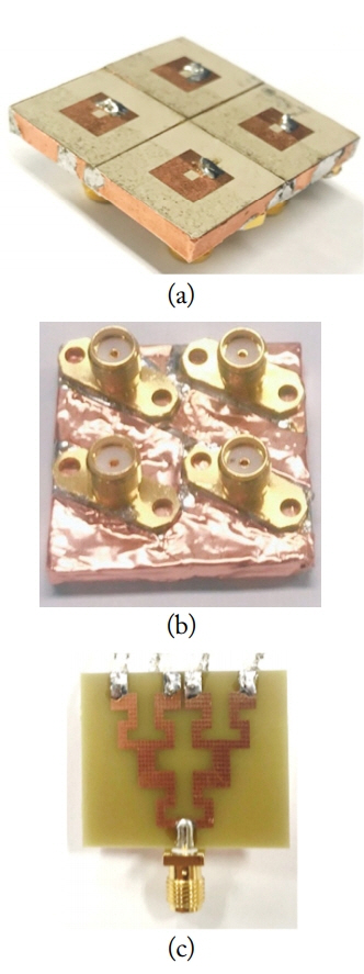
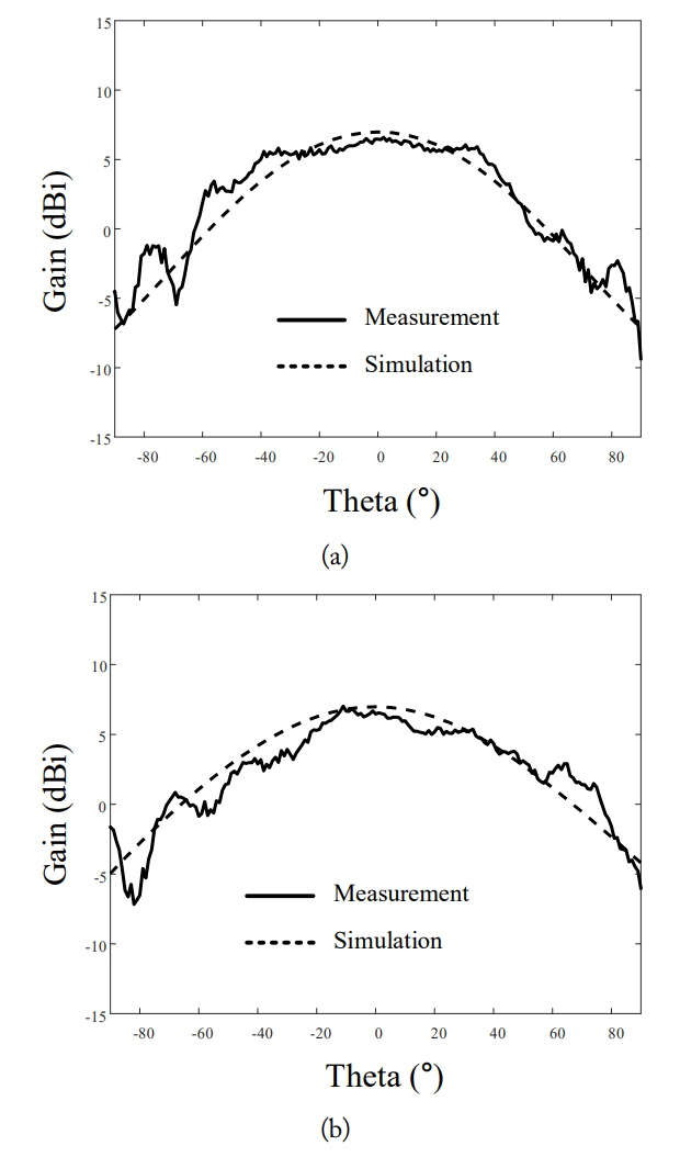
To verify the feasibility of the proposed 64-element array, a 2 ├Ś 2 downscaled array is fabricated and measured in a full-anechoic chamber. Fig. 10(a) and (b) show the perspective and bottom views of the fabricated 2 ├Ś 2 downscaled array, respectively. Each array element is fed by a SMA connector, and these 4 ports are connected to a 1 ├Ś 4 power divider printed on a FR4 ( ╔ør = 4.3, tan╬┤ = 0.0035) substrate of 33 mm ├Ś 29 mm ├Ś 1.6 mm. The measured and simulated radiation patterns of the fabricated array in zx- and zy-planes are indicated by the solid and dashed lines as shown in Fig. 11(a) and (b), respectively. As can be seen, the measured values agree well with the simulated results, and the array does not have any significant pattern distortion in the upper hemisphere. The transmission efficiency of the fabricated 2 ├Ś 2 array is 1% at a distance of 1 m when the 2 ├Ś 2 array is employed to both transmitting and receiving antennas.
IV. Conclusion
The design of a small array antenna with an extended cavity structure for WPT applications was investigated. The isolation characteristic was improved to more than 2 dB by inserting the extended cavity structure compared with the antenna without the cavity. The optimum element number of the array considering the input power for each element, fabrication cost, and aperture efficiency was determined to be 64. When the proposed array was applied to both transmitting and receiving antennas, a transmission efficiency of about 1% was observed at a distance of 2 m. The results demonstrate that the proposed small array with an extended cavity structure is suitable for wireless power transmission applications.