J. Electromagn. Eng. Sci Search

CLOSE


J. Electromagn. Eng. Sci > Volume 21(1); 2021 > Article
Purnamirza, Ibrahim, Susanti, Sutoyo, Mulyono, Radiles, and Rahmi: Cutting Technique for Constructing Small Radial Line Slot Array Antennas

Abstract

The design of small radial line slot array (RLSA) antennas requires more than simply decreasing the antenna radius, which leads to the problem of high reflection. To overcome this inconvenience, we introduce a technique for constructing small RLSA antennas with low reflection by cutting full-sized ones. We designed 42 ordinary full-size RLSA models with a radius of 75 mm and then cut them into 42 half RLSAs and 42 quarter RLSAs. The areas of the half RLSAs and the quarter RLSAs are equal to those of full-sized RLSAs with radii of 53 mm and 37 mm, respectively. Our results show that the gain of the quarter RLSA is less than that of the full RLSA by only 1 dB, whereas theoretically, the gain should decrease by 6 dB due to the size reduction. Interestingly, the gain of the half RLSAs is greater that of the full RLSA by 1 dB, whereas theoretically, a decrease of 3 dB was expected due to the size reduction. The half RLSA and the quarter RLSA also perform well in terms of reflection coefficient and bandwidth, thus demonstrating the efficacy of the cutting technique in constructing small low reflection RLSAs.

I. Introduction

Radial line slot array (RLSA) antennas have been receiving considerable attention since 1985 [1]. Originally, researchers developed high-gain RLSA antennas with diameters of no less than 600 mm to be used as receiver antennas for satellite communications [28]. Due to the advantages of this type of antenna, such as high gain and high efficiency [3, 5, 9], researchers have focused on the design of smaller versions, with diameters of less than 150 mm, for smaller antenna applications, such as millimeter waves [1012], mobile satellites [13], and wireless local area networks [1416].
For years, however, the development of small RLSA antennas has encountered the problem of high reflection coefficients due to their insufficient number of slots [2, 17]. Several research studies have proposed a number of solutions to overcome this problem [2, 1721]; among them, the extreme beamsquint technique is the most attractive [17]. Using this method, small RLSA antennas with a radius of 75 mm and at a frequency of 5.8 GHz could be designed without high reflection coefficients, which other techniques could not achieve previously. Several studies have also reported this technique’s success in the development of small low-reflection antennas for the Wi-Fi market [2226].
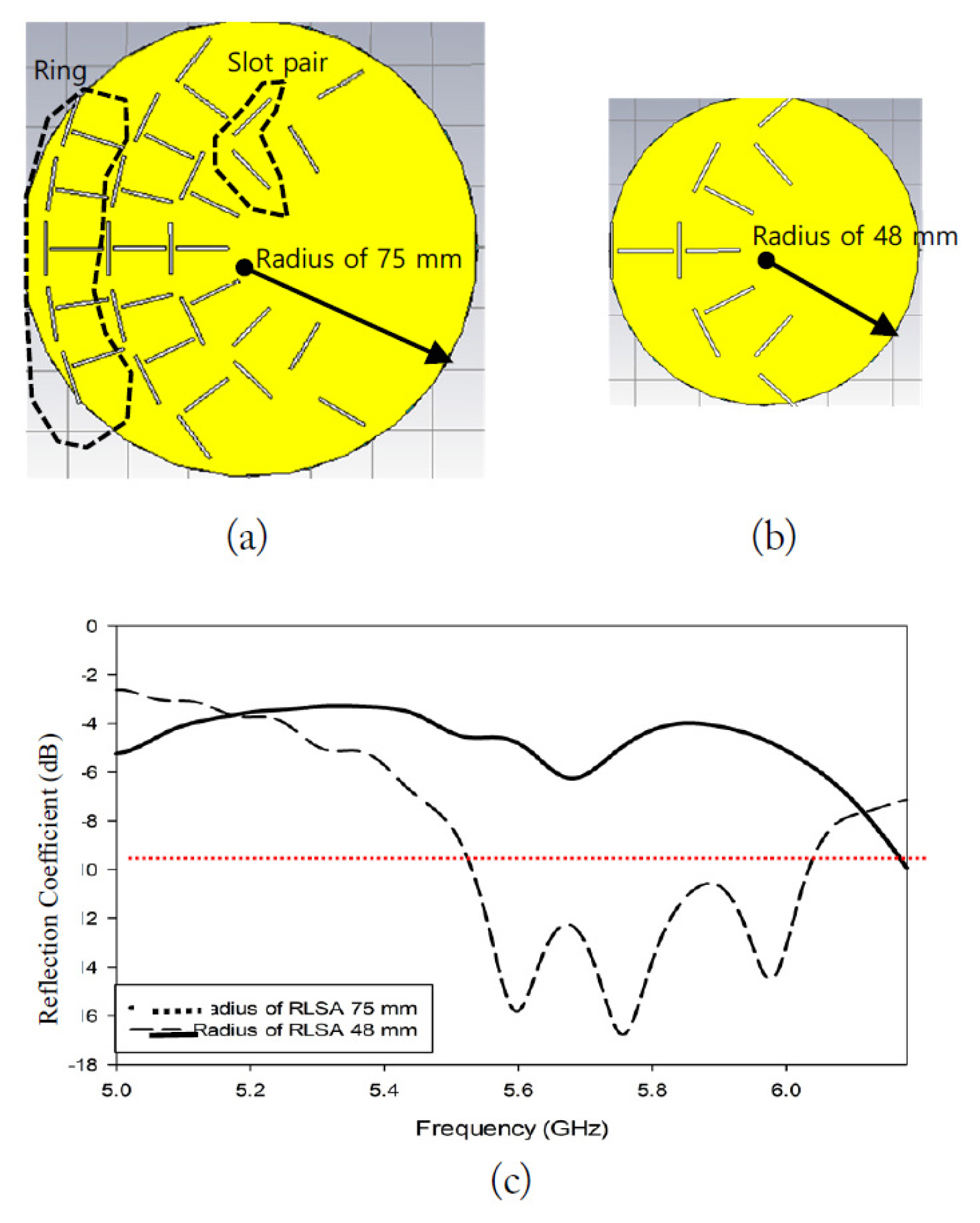
To design even smaller RLSA antennas, with radii less than 75 mm, we cannot simply reduce the antenna radius or use the extreme beamsquint technique directly. This is because reducing the antenna radius will significantly decrease the number of slots, which will then increase the reflection coefficient (see the illustration in Fig. 1). Fig. 1(a) shows a small RLSA antenna with a radius of 75 mm, 3 rings, and 19 slot pairs. This antenna has a good reflection coefficient (dotted line curve), as shown in Fig. 1(c). When we reduce the antenna size by decreasing its radius to 48 mm, there is only one ring, and the number of slot pairs significantly reduces to six, as shown in Fig. 1(b). This small number of slot pairs would not be able to radiate all the power from its feeder, so some power would remain in the antenna’s perimeter. This unused power would be reflected back to the feeder and increase the reflection coefficient. Fig. 1(c) shows the high reflection coefficient (solid line curve) of the antenna in Fig. 1(b).
As explained in the previous paragraph, decreasing the radius is not useful for developing small RLSA antennas, especially a radius less than 75 mm. Therefore, we introduce a technique for cutting RLSA antennas into small low-reflection ones. This is an unusual approach, as cutting results in the RLSA antennas no longer having the form of a full circle. Moreover, although such cutting could yield small low-reflection RLSAs, it may affect the gain due to power leakage along the cutting line.
In this paper, we first discuss in detail the cutting technique and its effect in Section II. In Section III, we report on the design and simulation of several antenna models: full-size, half, and quarter RLSAs. We also expand on the fabrication and measurement of the prototypes. To verify the cutting technique, in Section IV, we analyze and compare the simulation and measurement results in terms of reflection coefficient, bandwidth, and gain. Finally, in Section V, we conclude the analysis and provide some suggestions for future research.

II. The Cutting Technique and Its Effects

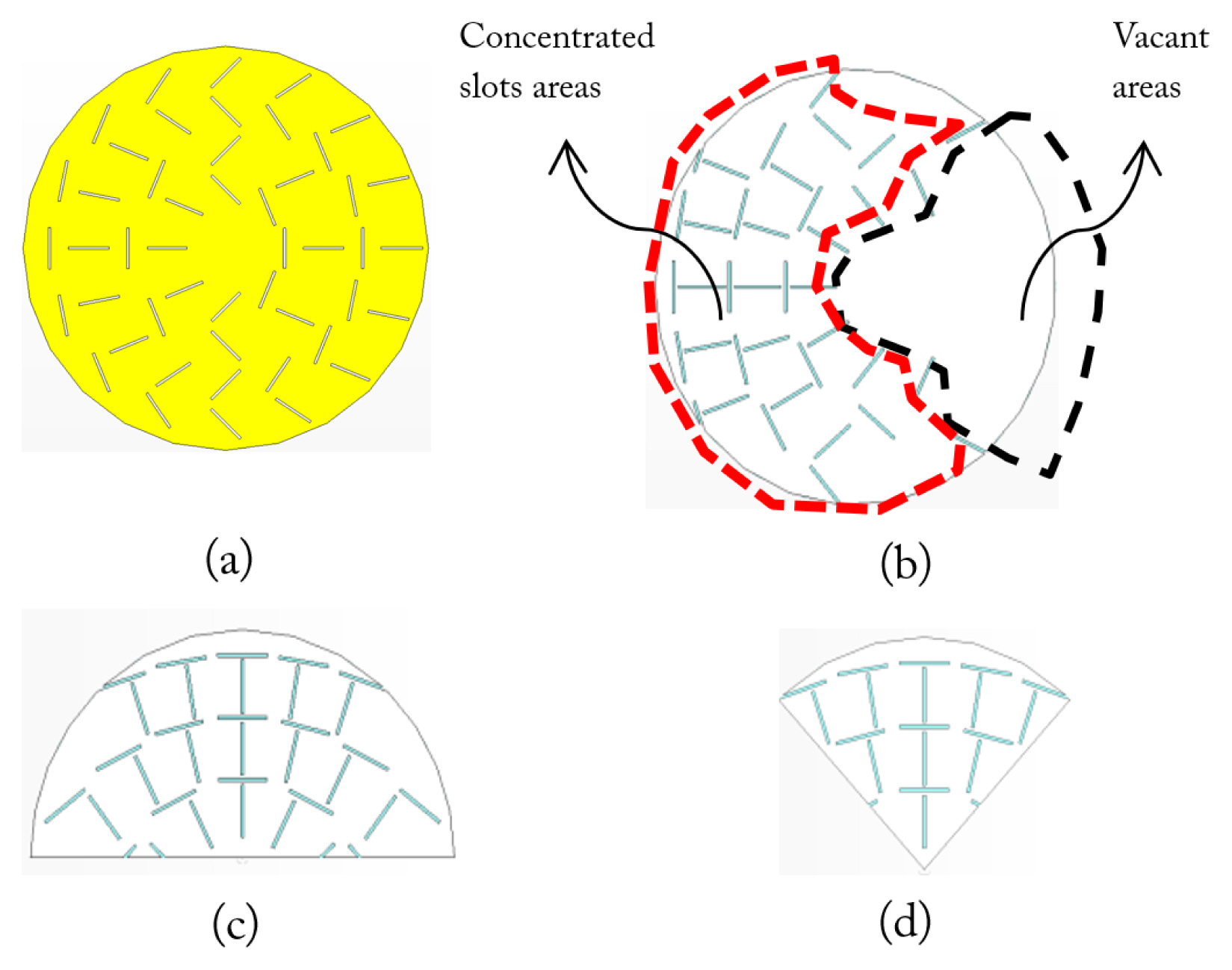
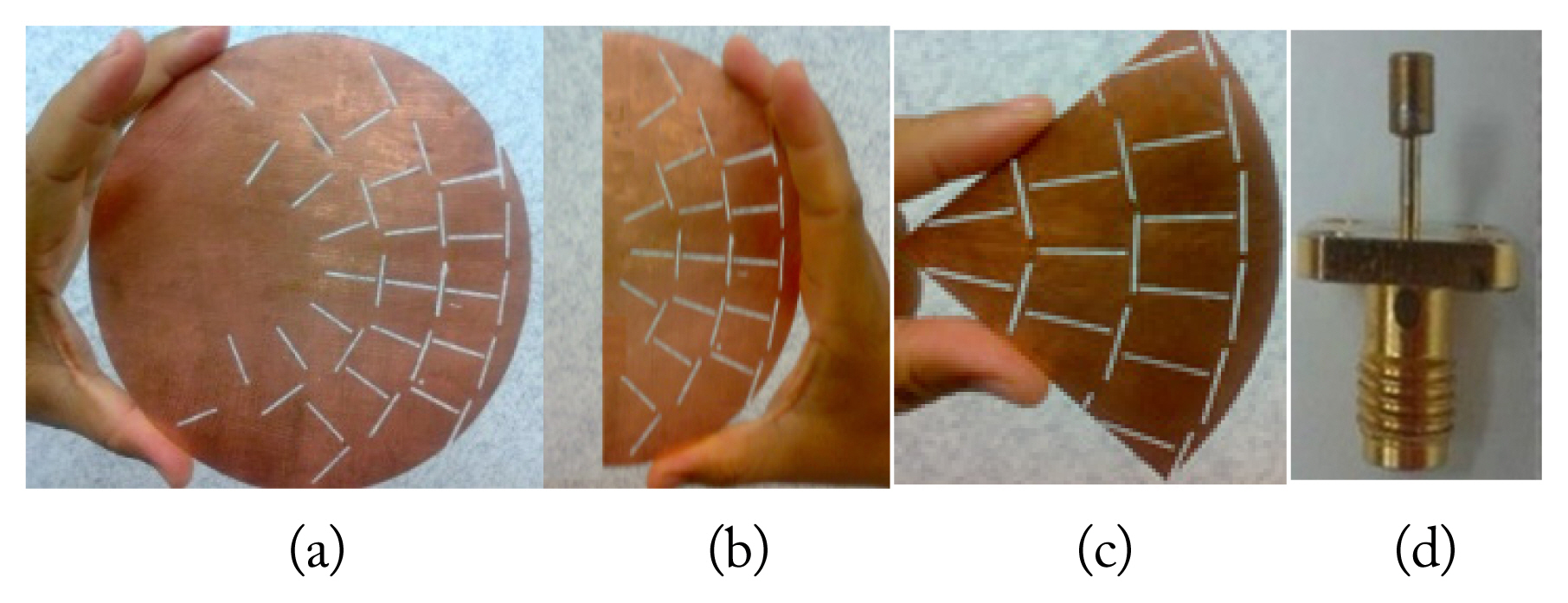
RLSA antenna slots are usually distributed uniformly on the entire surface of the antenna, as shown in Fig. 2(a). In order to have low reflection, a sufficient number of slots is required to radiate power. Therefore, the slots must be as close together as possible. We used high beamsquint values to design adjacent slots. The result of the design is a concentrated slot area and a vacant area, as shown in Fig. 2(b). The vacant area should not contribute to the antenna gain, since it has no slots to radiate power. We hypothesized that we might cut and remove the vacant area to produce a smaller antenna. Fig. 2(c) and (d) depict two smaller antennas resulting from these cuts.
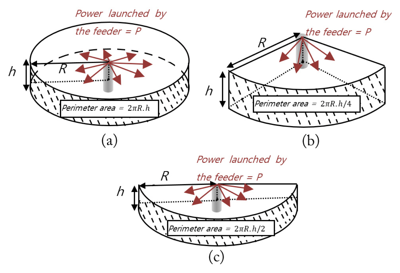
We further assumed that the cut RLSAs in Fig. 2(c) and (d) would have a power density inside the antenna cavity higher than that of the full RLSA in Fig. 2(b). More specifically, the power density should be about two times greater in the half RLSA and about four times greater in the quarter RLSA than in the full antenna. These increases occur because the perimeter areas of the quarter and half RLSAs are two times and four times smaller than that of the full RLSA, respectively. Fig. 3 illustrates the perimeter area of the antennas. We observe that the power density of the full RLSA, quarter RLSA, and half RLSA are P/2πRh, P/2πRh/4, and P/2πRh/2, respectively.
The higher power density should reduce the reflection coefficients, widen the bandwidth, and increase the gain, as more power will escape from these RLSAs’ slots compared to those of the full RLSA. Hence, less remaining power at the antenna’s perimeter will be reflected back to the feeder compared to the full RLSA, thereby reducing the reflection coefficient.
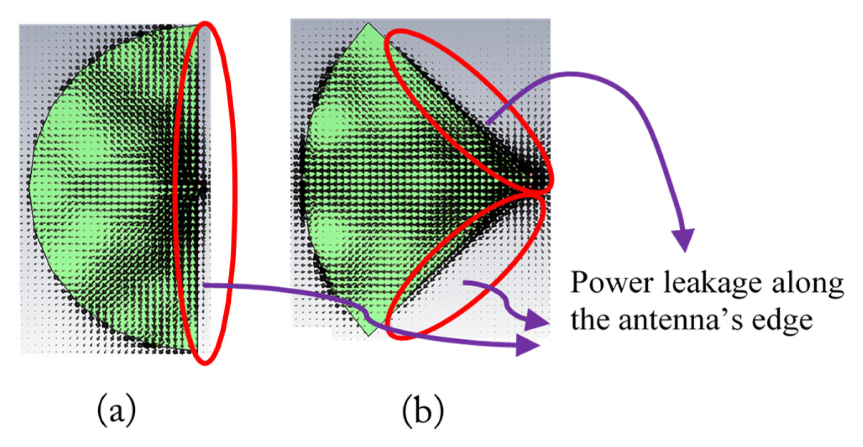
A negative effect of cutting is the power leakage along the cutting edge, as indicated by the simulation depicted in Fig. 4(a) and (b). The power leakage might reduce the gain since power escapes from the antenna without going through the slots, thus interfering with the gain’s focus. However, the effect of higher power density in the half and quarter RLSAs might compensate for the gain reductions due to the power leakage.

III. Antenna Models and Prototypes

We designed and simulated about 42 RLSA antenna models using high beamsquint values. All these models differed in terms of their beamsquint values (θ) and the number of slots in the first ring (p0) to ensure that the cutting technique is applicable for different cases. Furthermore, we cut each of the 42 models into 42 half RLSAs and 42 quarter RLSAs and performed simulations to analyze the cutting effect. Fig. 5 depicts a sample of the models before and after they were cut and a schematic of their feeder.
The antenna in Fig. 5(a) has an area of πr2 = π7.52 cm2 = 176.6 cm2, while the half antenna in Fig. 5(b) and the quarter antenna in Fig. 5(c) have an area of half and one-quarter of 176.6 cm2, or 88.3 cm2 and 44.15 cm2, respectively. This means the half antenna and the quarter antenna have areas equal to those of full antennas with radii of 53 mm and 37 mm, respectively.
The model consists of a radiating copper element at the top, a polypropylene cavity in the middle, a copper background on the back, and a feeder in the center. The feeder is an ordinary SMA (Sub-Miniature version A) feeder that we modified by adding a copper disk, as illustrated in Fig. 5(d). The disk is useful for modifying the coaxial transverse electromagnetic (TEM) mode signals into TEM cavity mode signals so that the signals generated by the feeder propagate in a radial direction within the antenna cavity.
The difficulty in drawing the antenna structure manually, especially the slots, led to the development of a computer program to draw the models’ structures faster and more accurately. All the design parameters of the antenna and feeder are listed in Table 1, while Fig. 5(a) and (d) depict their respective definitions.
Several equations were used in our code to calculate the inclination angle of the slot pairs (Eqs. (1) and (2)), their positions (Eqs. (3) and (4)), the distance between them (Eqs. (5) and (6)), and their lengths (Eq. (7)) [13]. Table 2 lists the definitions of the slot pair parameters in all the equations, while Fig. 6 was used to illustrate them.
(1)
θ1=π4+12{arctan(cos(θT)tan(T))-(-T)}
(2)
θ2=3π4+12{arctan(cos(θT)tan(T))-(-T)}
(3)
ρ1=(n-1+q-0.25)λg1-ξsinθTcos(φ-φT)
(4)
ρ2=(n-1+q+0.25)λg1-ξsinθTcos(φ-φT)
where ξ=1ɛr1
(5)
Sρ=λg1-ξsinθTcos(φ-φT)
(6)
Sφ=2πλg1-ξ2sinθT2qp
(7)
Lrad=(4.9876×10⁻³ρ)12.5×10⁹f0
After simulating all the models and their cut versions, we chose the three best models to fabricate. Fig. 7 depicts the built models for the full, half, and quarter RLSAs and their feeder. The prototypes were measured to verify the simulation results (see Fig. 8 for the measurement setup).

IV. Results and Discussion

1. Reflection Coefficients and Bandwidths

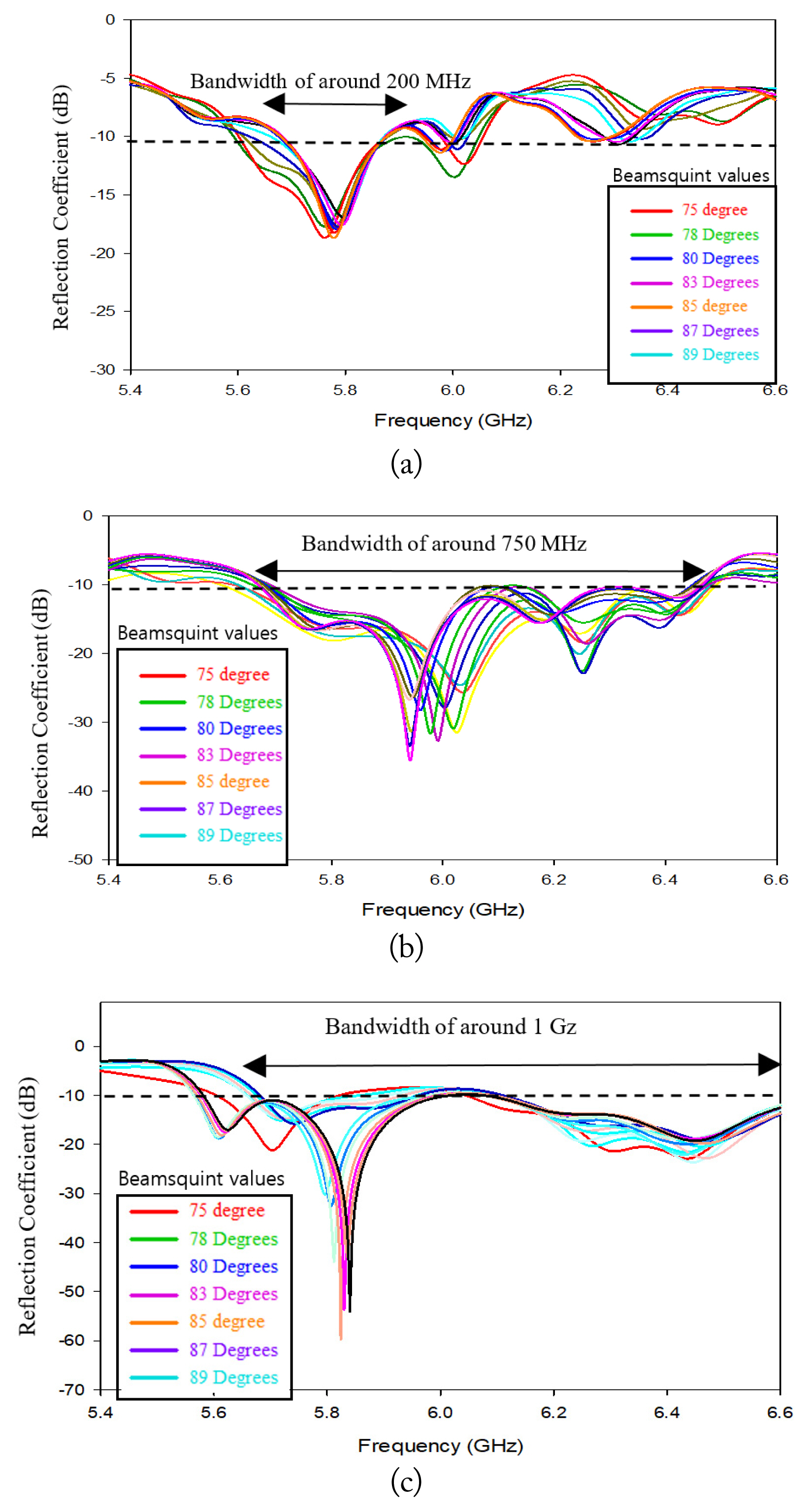
Fig. 9 illustrates the reflection coefficient of the antenna models for various beamsquint values. We observe that the quarter RLSAs have a lower reflection coefficient and wider bandwidth compared to those of the half RLSAs. We also notice that the half RLSAs have a lower reflection coefficient and wider bandwidth compared to those of the full RLSAs. This is because the quarter RLSA has a higher power density than the half RLSA, which in turn has a higher power density than the full RLSAs. As explained in Section II, a higher power density means a smaller amount of remaining power in the antenna perimeter, resulting in a smaller reflection coefficient and wider bandwidth in high-power-density compared to low-power-density antennas.
Based on the above results, we conclude that we can design small RLSAs with a radius less than 75 mm. This is done by cutting an RLSA with a 75 mm radius into half and quarter RLSAs, the area of which is equal to a full RLSA, with radii of 53 mm and 37 mm. Furthermore, with the cut RLSAs, we additionally benefit from widened bandwidth and lower reflections.

2. Gains

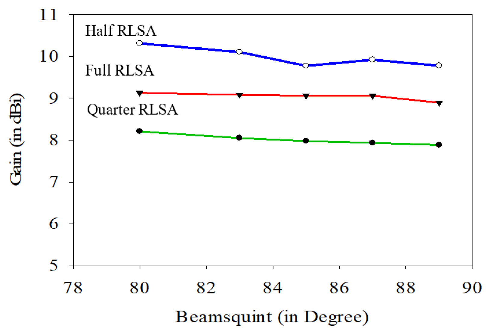
Fig. 10 displays the antenna gains for various beamsquint values for the quarter, half, and full RLSAs. We expected the quarter RLSAs to have a gain 6 dB (four times) lower than that of the full RLSA as a consequence of their four-fold size reduction. However, we observe that, on average, the quarter RLSAs have a gain about 1 dB lower than that of the full RLSAs. This unexpectedly small difference is due to the higher power density of the quarter RLSAs.
Another interesting result is that, on average, the half RLSAs have a gain that is greater by 1 dB than that of the full RLSAs, when the expected gain should be 3 dB (two times) lower than that of the full RLSAs. This happened for two reasons. First, if we observe Fig. 5(a) and (b), the half RLSA and the full RLSA have nearly the same number of slots, so their gain should be more or less the same. Second, the half RLSAs have a higher power density than the full RLSAs, as discussed in Section II.
Based on the above results, we conclude that the cut RLSAs have the additional benefit of maintained gain, increasing by about 1 dB and decreasing by only 1 dB for the half RLSA and quarter RLSA, respectively. This is notable, as the theoretical gain in the half and quarter RLSAs should be lower by 3 dB and 6 dB, respectively, due to their reduced sizes.

3. Comparison of a Half RLSA with Other Small RLSA Antennas

Comparisons of the area and gain of the half RLSA against other small RLSA antennas are listed in Table 3. We observe that although the area of the half RLSA is the smallest, the gain is still the best. As an example, compared to the antenna in the study [22], the area of the half RLSA is 5.74 times smaller. Since, theoretically, the gain should decrease linearly with the decrease of the area, the gain of the half RLSA should be 5.74 times smaller, although in reality, it is only 4.47 times smaller. We observe similar results when comparing our findings with other references; an extreme case is [17]. Although the area of the half RLSA is two times smaller, the gain is 1.41 times higher than expected (0.707 smaller than that in the study [17]). Despite these results, the research aim is not to increase gains, but to obtain smaller RLSA antennas with low levels of reflection and sufficient gains.

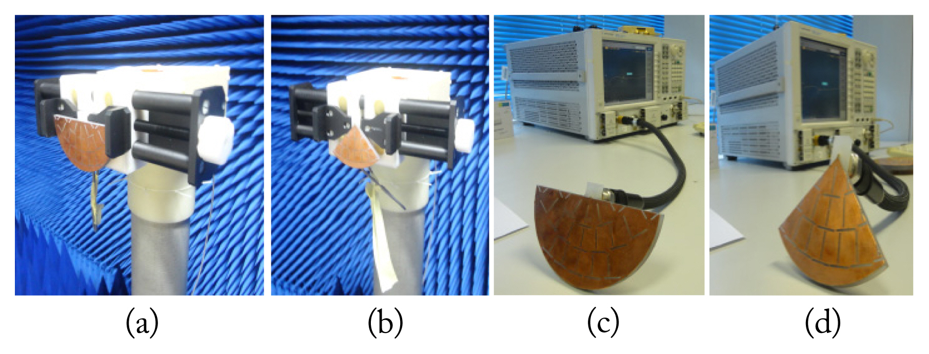
4. Comparison between Simulations and Measurements

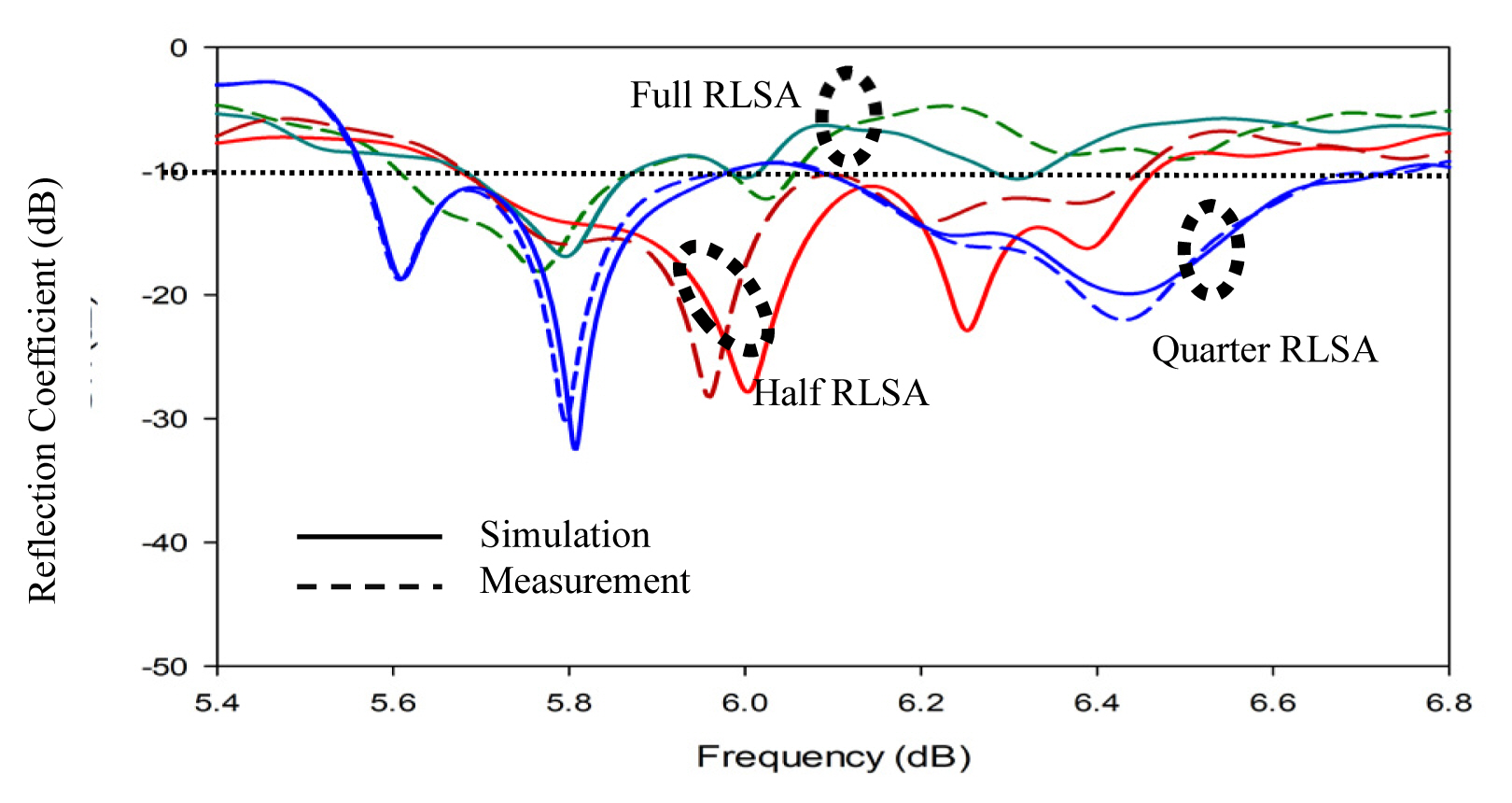
Fig. 11 plots the simulated and measured reflection coefficients. We observe that the half and quarter RLSAs have lower reflection coefficients and wider bandwidths than the full RLSAs.
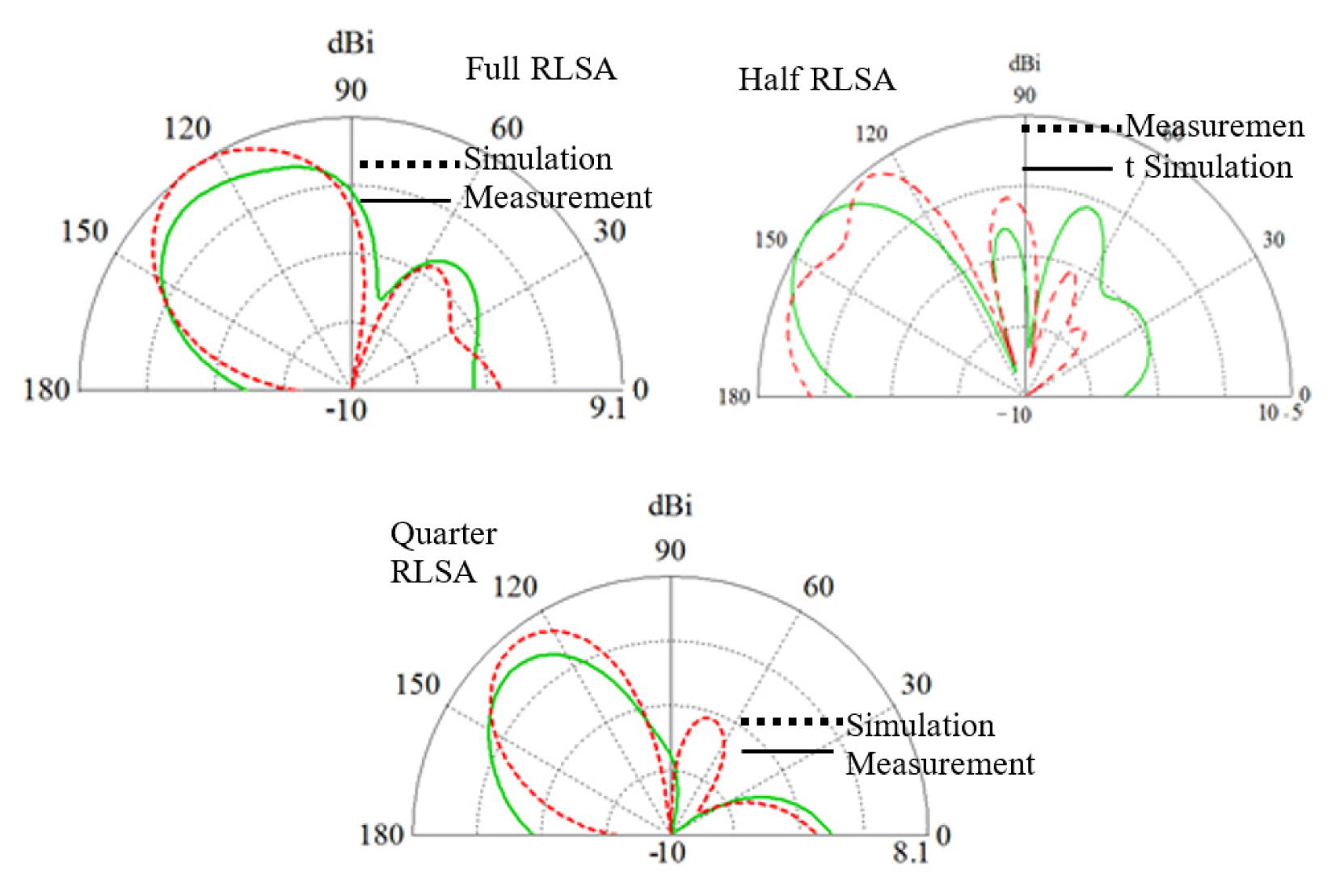
Fig. 12 depicts the measured and simulated radiation patterns, showing that the half RLSA has a higher gain (10.5 dBi) than the full (9.1 dBi) and quarter RLSAs (8.1 dBi).
Figs. 11 and 12 illustrate that the simulations agree with the measurements. The slight deviation in the measurement results is due to imperfections in fabricating the prototypes, especially in printing the radiating element’s design and drilling the antenna’s feeder hole and soldering the head disk at the correct positions.
Finally, based on the simulation and measurement results, we have verified our hypothesis that the cutting technique is effective for designing small low reflection RLSA antennas without significantly decreasing gain. The fabricated half and quarter RLSA antennas have areas equal to those of full antennas with radii of 53 mm and 37 mm. Furthermore, we demonstrated that, by cutting RLSA antennas, we achieve even wider bandwidths.

V. Conclusion

We introduced a technique of cutting RLSA antennas to create small, low-reflection ones. We demonstrated that this technique could be used to construct the smallest RLSA antennas to date. The areas of the fabricated half and quarter RLSA antennas are equal to those of full RLSAs with radii of 53 mm and 37 mm, respectively, without significantly reducing gain. In fact, in one case (the half cut), the gain increased by about 1 dB. We also revealed that the designed small RLSAs have wider bandwidths and lower reflection coefficients. This technique is expected to be a significant step in producing small low reflection RLSA antennas with sufficient gains for small devices, such as wireless bridges. The antennas designed in this research are low profile, just like microstrip antennas but better due to their well-known high efficiency. Therefore, it is possible to use them as an alternative for microstrip antennas. Future research should apply this technique to design small RLSA antennas for other values of the radius and other frequencies.

Fig. 1
(a) Cross section of an RLSA antenna with a 75-mm radius. (b) Cross section of an RLSA antenna with a 48-mm radius. (c) The reflection coefficients of the antennas.
jees-2021-21-1-35f1.jpg
Fig. 2
Cross sections of (a) a regular RLSA antenna, (b) an RLSA antenna designed using a high beamsquint value, (c) cut in half and (d) in quarters.
jees-2021-21-1-35f2.jpg
Fig. 3
Perimeter area of a (a) full RLSA, (b) quarter RLSA, and (c) half RLSA.
jees-2021-21-1-35f3.jpg
Fig. 4
(a) Power leakage in the half RLSA and (b) quarter RLSA.
jees-2021-21-1-35f4.jpg
Fig. 5
Model of the (a) full RLSA, (b) half RLSA, (c) quarter RLSA, and (d) feeder.
jees-2021-21-1-35f5.jpg
Fig. 6
(a) Slot pairs along with all parameters in the x–y plane, (b) slot positions and their relations to the beam direction in x– y–z, and (c) distance between slots in the radial and azimuthal directions [1, 3].
jees-2021-21-1-35f6.jpg
Fig. 7
A prototype of the (a) full RLSA, (b) half RLSA, (c) quarter RLSA, and (d) feeder.
jees-2021-21-1-35f7.jpg
Fig. 8
(a, b) Measurement setup of the prototypes in an anechoic chamber and (c, d) using a network analyzer.
jees-2021-21-1-35f8.jpg
Fig. 9
Reflection coefficients for various beamsquint values of the (a) full RLSAs, (b) half RLSAs, and (c) quarter RLSAs.
jees-2021-21-1-35f9.jpg
Fig. 10
Gain for various beamsquint values.
jees-2021-21-1-35f10.jpg
Fig. 11
Comparison between the measured and simulated reflection coefficients.
jees-2021-21-1-35f11.jpg
Fig. 12
Comparison between the measured and simulated radiation patterns for the full, half, and quarter RLSA antennas.
jees-2021-21-1-35f12.jpg
Table 1
Specification parameters of the antenna models and feeder [17, 18]
Symbol Parameter Value
f Frequency 5.8 GHz
r Antenna radius 75 mm
n Number of slot pairs in the first ring 10, 12, 14, 16
θ Beamsquint angle 75° up to 89°
d1 Cavity thickness 8 mm
d2 Radiating element thickness 0.1 mm
d Background thickness 0.1 mm
ɛr1 Cavity permittivity 2.33
h Disk height 3 mm
ra Disk radius 1.4 mm
b1 Lower air gap 4 mm
b2 Upper air gap 1 mm
Table 2
Design parameters of the slot pairs [1, 3]
Parameters Symbol
Inclination angle of Slot 1 θ1
Inclination angle of Slot 2 θ2
Beamsquint angle in the elevation direction θT
Azimuthal angle of Slot 1 and Slot 2 position φ
Beamsquint angle in the azimuthal direction φT
Distance from Slot 1 to the center point of the antenna ρ1
Distance of from Slot 2 to the center point of the antenna ρ2
Number of slot pairs in the first ring n
Integer numbers (1, 2, 3…) that express the distance from the innermost ring to the center of the antenna q
Radial distance between two adjacent unit radiators located in two different rings Sρ
Azimuthal distance between two adjacent unit radiators in the same ring Sφ
Table 3
Comparison of the half RLSA with other small RLSA antennas
References Radius (cm) / area (cm2) Area of the reference small RLSA antenna divided by the area of the half RLSA antenna Gain (dBi) Gain of the reference small RLSA antenna divided by the gain of the half RLSA antenna
[17] 7.5 / 176.62 2 9 0.707
[18] 7.5 / 176.62 2 12 1.41
[22] 12.7 / 506.45 5.74 17 4.47
[23] 14 / 615.44 7 18.4 6.17
[24] 11.5 / 412.56 4.7 17.28 4.76
[25] 12.3 / 475.05 5.4 17.53 5.05
[26] 10.7 / 359.50 4.07 16.25 3.76

References

1. M Ando, K Sakurai, N Goto, K Arimura, and Y Ito, "A radial line slot antenna for 12 GHz satellite TV reception," IEEE Transactions on Antennas and Propagation, vol. 33, no. 12, pp. 1347–1353, 1985.
crossref
2. M Takahashi, JI Takada, M Ando, and N Goto, "A slot design for uniform aperture field distribution in single-layered radial line slot antennas," IEEE Transactions on Antennas and Propagation, vol. 39, no. 7, pp. 954–959, 1991.
crossref
3. PW Davis and ME Bialkowski, "Experimental investigations into a linearly polarized radial slot antenna for DBS TV in Australia," IEEE Transactions on Antennas and Propagation, vol. 45, no. 7, pp. 1123–1129, 1997.
crossref
4. M Ando, T Numata, JI Takada, and N Goto, "A linearly polarized radial line slot antenna," IEEE Transactions on Antennas and Propagation, vol. 36, no. 12, pp. 1675–1680, 1988.
crossref
5. JF Gonzalez, P Padilla, G Exposito-Dominguez, and M Sierra-Castaner, "Lightweight portable planar slot array antenna for satellite communications in X-band," IEEE Antennas and Wireless Propagation Letters, vol. 10, pp. 1409–1412, 2011.
crossref
6. JI Takada, M Ando, and N Goto, "A reflection cancelling slot set in a linearly polarized radial line slot antenna," IEEE Transactions on Antennas and Propagation, vol. 40, no. 4, pp. 433–438, 1992.
crossref
7. H Sasazawa, Y Oshima, K Sakurai, M Ando, and N Goto, "Slot coupling in a radial line slot antenna for 12-GHz band satellite TV reception," IEEE Transactions on Antennas and Propagation, vol. 36, no. 9, pp. 1221–1226, 1988.
crossref
8. M Sierra-Castaner, M Sierra-Perez, M Vera-Isasa, and JL Fernandez-Jambrina, "Low-cost monopulse radial line slot antenna," IEEE Transactions on Antennas and Propagation, vol. 51, no. 2, pp. 256–263, 2003.
crossref
9. Y Wang, H Xiao, G Lu, J Lin, and T Li, "The investigation for a circularly polarized radial line slot antenna with low side lobes and high gain," In: Proceedings of 2012 International Conference on Microwave and Millimeter Wave Technology (ICMMT); Shenzhen, China. 2012, pp 1226–1227.
crossref
10. Y Kim, J Lee, H Chae, J Park, SC Kim, and S Nam, "60 GHz band radial line slot array antenna fed by rectangular waveguide," Electronics Letters, vol. 38, no. 2, pp. 59–60, 2002.
crossref
11. K Sudo, A Akiyama, J Hirokawa, and M Ando, "A millimeter-wave radial line slot antenna fed by a rectangular waveguide through a ring slot," IEICE Transactions on Electronics, vol. 84, no. 10, pp. 1521–1527, 2001.
crossref
12. R Jin, H Zhu, and M Ando, "A feeding circuit with CPW for CA-RLSA," IEEE Transactions on Antennas and Propagation, vol. 49, no. 12, pp. 1862–1867, 2001.
crossref
13. JI Takada, T Yamamoto, M Ando, and N Goto, "Circularly polarized multibeam radial line slot antennas for mobile satellite communication," In: Proceedings of IEEE Antennas and Propagation Society International Symposium; Newport Beach, CA. 1995, pp 1430–1433.
crossref
14. KS Bialkowski and S Zagriatski, "Investigations into a dual band 2.4/5.2 GHz antenna for WLAN applications," In: Proceedings of the 15th International Conference on Microwaves, Radar and Wireless Communications (IEEE Cat No 04EX824); Warsaw, Poland. 2004, pp 660–663.
crossref
15. S Zagriatski and ME Bialkowski, "Circularly polarised radial line slot array antenna for wireless LAN access point," In: Proceedings of the 15th International Conference on Microwaves, Radar and Wireless Communications (IEEE Cat No 04EX824); Warsaw, Poland. 2004, pp 649–652.
crossref
16. TA Rahman, IM Ibrahim, PS Wei, and J Ahmad, "A study on effectiveness of FR4 as a dielectric material for radial line slot array antenna for wireless backhaul application," In: Proceedings of the 17th Asia Pacific Conference on Communications; Sabah, Malaysia. 2011, pp 385–388.
crossref
17. T Purnamirza, TA Rahman, and MH Jamaluddin, "The extreme beamsquint technique to minimize the reflection coefficient of very small aperture radial line slot array antennas," Journal of Electromagnetic Waves and Applications, vol. 26, no. 17–18, pp. 2267–2276, 2012.
crossref
18. T Purnamirza and TA Rahman, "A novel technique in simplifying the fabrication process and improving the reflection coefficient of the linear polarized radial line slot array (LP-RLSA) antennas," Journal of Electromagnetic Waves and Applications, vol. 26, no. 4, pp. 535–548, 2012.
crossref
19. A Akiyama, T Yamamoto, M Ando, and N Goto, "Numerical optimisation of slot parameters for a concentric array radial line slot antenna," IEE Proceedings-Microwaves, Antennas and Propagation, vol. 145, no. 2, pp. 141–146, 1998.
crossref
20. A Akiyama, T Yamamoto, M Ando, N Goto, and E Takeda, "Design of radial line slot antennas for millimeter wave wireless LAN," In: Proceedings of IEEE Antennas and Propagation Society International Symposium Digest; Montreal, Canada. 1997, pp 2516–2519.
crossref
21. J Hirokawa, K Sakurai, M Ando, and N Goto, "Matching slot pair for a circularly-polarised slotted waveguide array," IEE Proceedings H (Microwaves, Antennas and Propagation), vol. 137, no. 6, pp. 367–371, 1990.
crossref
22. T Purnamirza, S Hasbi, IM Bin Ibrahim, F Amillia, and D Rahmi, "A radial line slot array (RLSA) antenna with the specifications of 16 dBi outdoor patch antenna," Telkomnika, vol. 16, no. 1, pp. 46–52, 2018.
crossref
23. T Purnamirza, D Kristanto, and IM Ibrahim, "A design of compact radial line slot array (RLSA) antennas for Wi-Fi market needs," Progress In Electromagnetics Research, vol. 64, pp. 21–28, 2016.
crossref
24. T Purnamirza, IM Ibrahim, P Prowadi, and F Amillia, "Small radial line slot array (RLSA) antennas for Wi-Fi 5.8 GHz devices," International Journal on Communications, Antenna and Propagation (IRECAP), vol. 7, no. 5, pp. 397–402, 2017.
crossref
25. T Purnamirza, P Budikesuma, IM Bin Ibrahim, D Rahmi, and R Susanti, "A small RLSA antenna utilizing the specification of back fires 17 dBi LAN antennas," Telkomnika, vol. 16, no. 6, pp. 2871–2878, 2018.
crossref
26. T Purnamirza, M Ralibi, IM Bin Ibrahim, S Susanti, H Mudia, and D Rahmi, "A design of radial line slot array antennas using the specification of panel antennas," Telkomnika, vol. 17, no. 6, pp. 3066–3072, 2019.
crossref

Biography

jees-2021-21-1-35i1.jpg
Teddy Purnamirza was born in Pekanbaru, Indonesia, on October 30th, 1974. He received his Bachelor of Electrical Engineering from STTTelkom (currently Telkom University), Bandung, West Java, Indonesia, in 2000. In 2005 and 2013, he obtained his master’s and doctoral degrees, respectively, both in electrical engineering, from UTM, Johor, Malaysia. He joined the Informatic Engineering Department at UIN Suska in 2000. From 2000 to 2003, he was head of the Informatics Laboratory. In 2003, he joined the Electrical Engineering Department at UIN Suska. From 2005 to 2007, he was head of the Computer Laboratory. In 2007, he was appointed head of the Electrical Engineering Department at UIN Suska, a position he held until 2010. From 2013 to 2018, he was the Vice Dean for academic affairs and institution development at the Faculty of Science and Technology at UIN Suska. Dr. Purnamirza is now serving as an associate professor at the same university. He has published three books, one book chapter, fifteen journal papers, and four conference papers. His research interests are antennas and propagations.

Biography

jees-2021-21-1-35i2.jpg
Imran Mohd Ibrahim is Senior Lecturer at Universiti Teknikal Malaysia Melaka and now serve as Head of Microwave Research Group. He received his bachelor, master and doctoral degree from Universiti Teknologi Malaysia, all in electrical engineering, in 2000, 2005, and 2016, respectively. He served as faculty’s first Deputy Dean (Research and Post Graduate Study) and contributed to the early development of research activities at faculty and institution. He has lead several grants from industry, government and university in antenna research and wireless communication. He is also a committee member to draft the Technical Code in 5G Safety Radiation to Malaysia Technical Standard Forum Berhad. He has published more than 70 journals and conference papers. His research interests are antenna and microwave device design. He also supervised a PhD and Master students by research in antenna design for 5G and medical application.

Biography

jees-2021-21-1-35i3.jpg
Rika Susanti was born in Pekanbaru, Indonesia, on July 31, 1977. She received her bachelor’s and master’s degrees in electrical engineering from Diponegoro University, Semarang, Central Java, Indonesia, in 2003 and UTM, Johor, Malaysia in 2010, respectively. She joined the Electrical Engineering Department of UIN Suska in 2004. She is now serving as senior lecturer at UIN Suska. She has published three books, two journal papers, and nine conference papers. Her main research interest is in the area of optical communication systems.

Biography

jees-2021-21-1-35i4.jpg
Sutoyo was born in Kampar, Indonesia, on December 2nd, 1984. He received his bachelor’s degree in electrical engineering from UIN Suska in 2008. In 2012, he received his master’s degree from the Institut Teknologi Sepuluh Nopember (ITS), Surabaya, East Java, Indonesia. He joined the Electrical Engineering Department at UIN Suska in 2008. He is now serving as a senior lecturer and head of the quality assurance committee at the Faculty of Science and Technology at UIN Suska. He has published two books, two journal papers, and three conference papers. His research interests are antennas and propagations.

Biography

jees-2021-21-1-35i5.jpg
Mulyono was born in Dumai, Indonesia, on November 15, 1985. He received his bachelor’s degree in electrical engineering from UIN Suska Riau in 2008. In 2012, he received his master’s degree from the Institut Teknologi Sepuluh Nopember (ITS), Surabaya, East Java, Indonesia. He joined the Electrical Engineering Department at UIN Suska in 2008. He is now serving as senior lecturer and secretary of the Electrical Engineering Department at UIN Suska. He has published two books, two journal papers, and four conference papers. His research interest lies in wireless communication.

Biography

jees-2021-21-1-35i6.jpg
Hasdi Radiles was born in Pekanbaru, Indonesia, on September 9, 1977. He received his bachelor’s and master’s degrees in electrical engineering from STTTelkom (currently Telkom University), Bandung, West Java, Indonesia, in 2000 and 2005, respectively. He has worked at Huawei Tech Investment, Indonesia, as a professional in 3G radio network planning and optimization. In 2010, he joined the Electrical Engineering Department at UIN Suska Riau. His research interests are antennas and propagations.

Biography

jees-2021-21-1-35i7.jpg
Depriwana Rahmi was born in Pekanbaru, Indonesia, on March 6th, 1981. She received her bachelor’s and master’s degrees from Universitas Riau, Pekanbaru, Riau and UTM Malaysia, Johor, Malaysia, in 1999 and 2015, respectively. She joined the Mathematics Education Department at UIN Suska in 2006. She is now serving as senior lecturer at the same university.

ABOUT
ARTICLE CATEGORY

Browse all articles >

BROWSE ARTICLES
AUTHOR INFORMATION
Editorial Office
#706 Totoo Valley, 217 Saechang-ro, Yongsan-gu, Seoul 04376, Korea
Tel: +82-2-337-9666    Fax: +82-2-6390-7550    E-mail: admin-jees@kiees.or.kr                

Copyright © 2024 by The Korean Institute of Electromagnetic Engineering and Science.

Developed in M2PI

Close layer
prev next