I. Introduction
The dielectric constant reflects the polarity and molecular structure-dependent electrical properties of a material [1]. Measuring the dielectric constant non-invasively is useful for determining the type and composition of materials without destroying or damaging the target sample [2]. In various industrial applications, the measurement is presented as a relative dielectric constant after calibration with standard materials. Because the dielectric constant of a mixture or compound can vary with the uniformity and anisotropy of the materials, the measurement results for even a homogeneous material can be sensitively changed by environmental factors such as the humidity, temperature, and measurement frequency [3–5].
Non-invasive dielectric constant measurement methods, based on monitoring the characteristic variations generated as electromagnetic (EM) wave signals, are reflected at or transmitted through the target sample [6]. Measurement methods can be classified into two groups: (1) methods that detect the shift of a specific resonant frequency (resonant methods) and (2) methods that monitor the changes in the EM wave characteristics over a wide frequency band (non-resonant methods). Non-resonant methods can measure the relative dielectric constant of various materials without considering the frequency selectivity and response of the target sample, but the detection sensitivity is relatively low and the performance is limited by the model that converts the measured data into the dielectric constant [7–9]. Resonant methods can achieve high sensitivity and selectivity in determining the dielectric constant of a target sample located around the resonator [10]. The resonator in these methods should have a high quality-factor (Q-factor) so that the resonant frequency can be sensitively changed by the EM field distribution around the resonator. A planar-type resonator implemented using microstrip transmission lines has numerous advantages, such as low-cost manufacture, easy implementation, and real-time measurement [11]. Most resonant structures are based on the split-ring resonator (SRR), which makes use of the resonance between two concentric circles with the same center and different radii [12]. Using a complementary split-ring resonator (CSRR) consisting of a ground plane with the SRR pattern and a signal transmission line coupled with the patterned plane can increase the sensitivity of the dielectric constant measurement [13–16]. However, the physical dimensions and types of the target samples are limited because the sample should be located only on the resonance pattern.
In this paper, we propose a double split-ring resonator (DSRR) structure that can measure the dielectric constants of both solid and liquid samples with high sensitivity using only a single structure. A high Q-factor is achieved in the proposed resonator, which consists of two asymmetrical rectangular split-rings that generate a single resonant frequency in the 2.45 GHz band. The dielectric constants of six solid reference samples with different dielectric constants were calculated from the resonant frequency shift by using a quadratic equation to model the resonant shift. To measure liquids, the proposed resonator monitors the changes in the dielectric constant depending on the ethanol concentration using a quadratic equation that has the same formula but different parameters from the equation for solid samples. The measurement results show that the proposed resonator can measure the dielectric constants of both solid and liquid samples with high sensitivity and low error over a wide range of dielectric constants. Section II presents the design and implementation, including the EM simulation results of the proposed resonator in the 2.45 GHz band. Section III presents the measurement results for the dielectric constants of the solid and liquid samples based on the numerical model equations, and the sensitivity and errors in the measurements using the proposed resonator are discussed. Section IV presents the conclusions.
II. Design and Implementation of the Proposed Resonator
1. DSRR Design
A conventional SRR consists of two equally spaced concentric metal rings and can be modeled simply by an equivalent parallel LC resonator circuit [17]. The dielectric constant of the material under test (MUT) is indirectly measured from the shift in the resonant frequency due to the capacitance change ΔC caused by the effective dielectric constant of the MUT located around the SRR. A resonator structure that increases ΔC or the effect of the effective dielectric constant on ΔC by the MUT is necessary for increasing the sensitivity of the dielectric constant measurement. A resonator that simply increases ΔC is not effective in increasing the ratio of the resonant frequency shift because the intrinsic capacitance increases simultaneously with ΔC in the resonator structure.
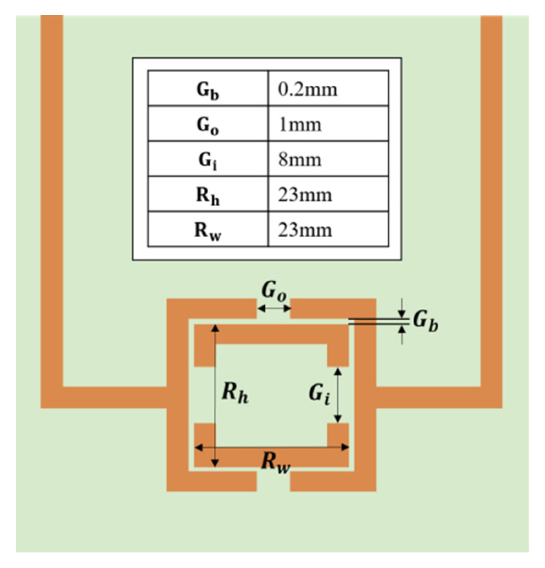
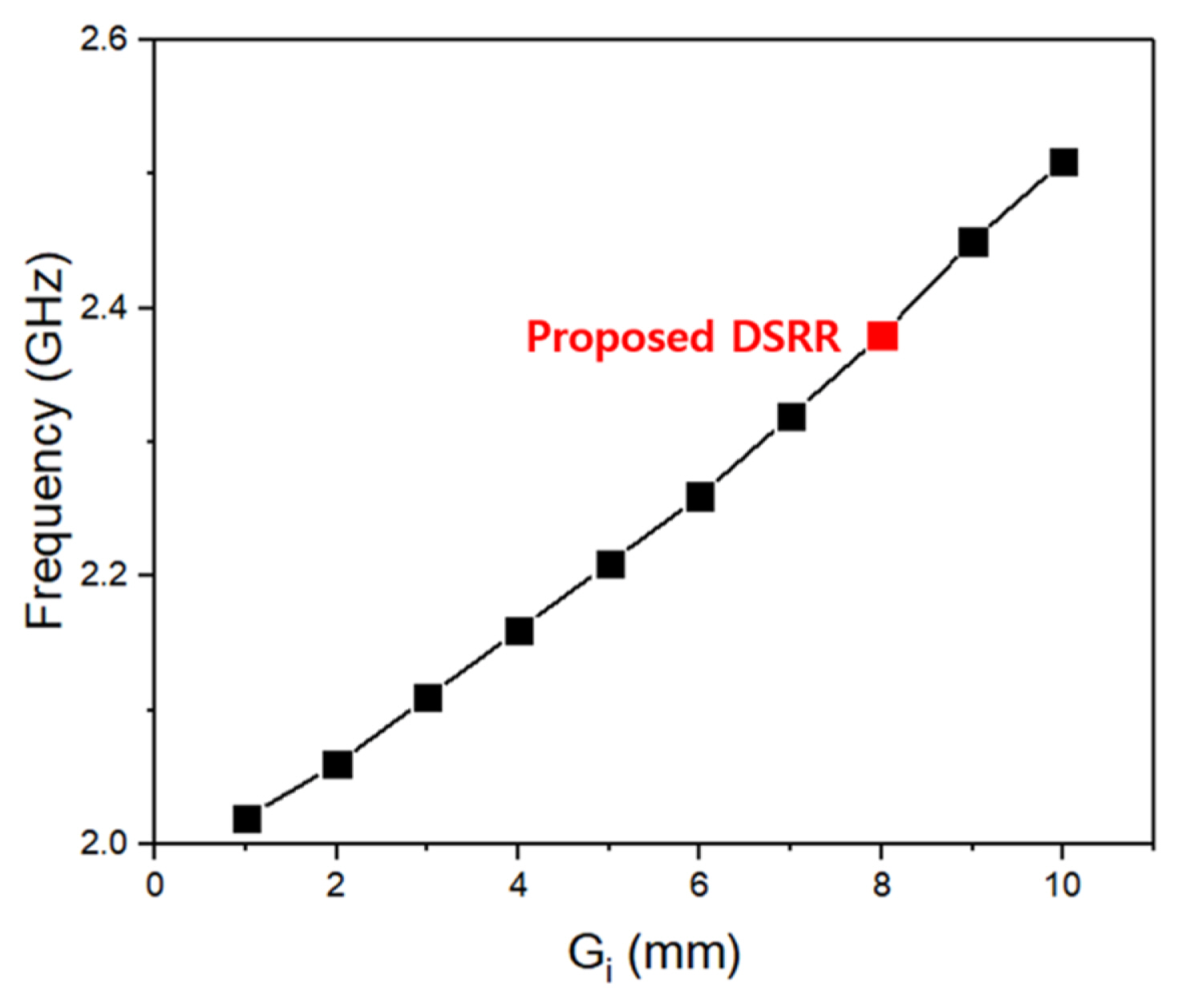
We increase ΔC and decrease the intrinsic inductance so that the frequency shift due to ΔC is increased. Fig. 1 shows the proposed DSRR. The proposed resonator consists of two concentric rectangular rings with asymmetric splits. The capacitance of the resonator is increased by using a small spacing of 0.2 mm between two rings, which is the minimum spacing that can be realized uniformly in the PCB fabrication process. The asymmetric splits of the two rings decrease the intrinsic inductance due to magnetic coupling without dramatically reducing the capacitance by separating the current path. The design parameter Gi in Fig. 1 is important for determining the resonant frequency of the DSRR. The Gi and the resonant frequency are proportional, as shown in Fig. 2, because the equivalent capacitance and inductance of the DSRR simultaneously decrease as the Gi increases.
The Q-factor of the proposed resonator is improved by the increase in the resonant frequency resulting from the reduction of the intrinsic inductance and the decrease in the resistivity loss due to the removal of the metal line.
2. Implementation of the Proposed DSRR
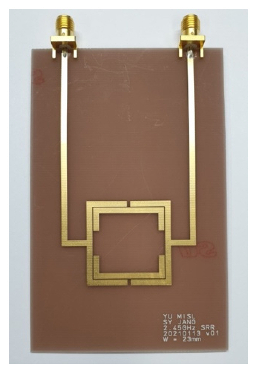
Fig. 3 shows a photograph of the proposed resonator fabricated on a 1-mm thick FR4 PCB. The proposed resonator is designed to have long feedlines located in one direction for measuring solid MUTs of various sizes and for allowing the entire resonator to be immersed in the liquid under test (LUT). The total size of the fabricated resonator with the port is 63.2 mm in the horizontal direction and 98.6 mm in the vertical direction.
Fig. 4 shows the simulation and measurement results of the proposed DSRR. The measurement results for the resonant characteristics in the 2.45 GHz frequency band agree well with the EM simulation results obtained from the Keysight Advanced Design System software. The bare DSRR without any MUT load has a resonant frequency fr0 of 2.42 GHz, a notch depth of −19.2 dB, and a Q-factor of 129. The smaller resonant frequency and larger Q-factor in the measurement compared to the simulation results are due to the smaller metal spacing and the surface resistance of the gold plating in the fabricated resonator.
III. Dielectric Constant Measurements
1. Measurement of Solid MUTs
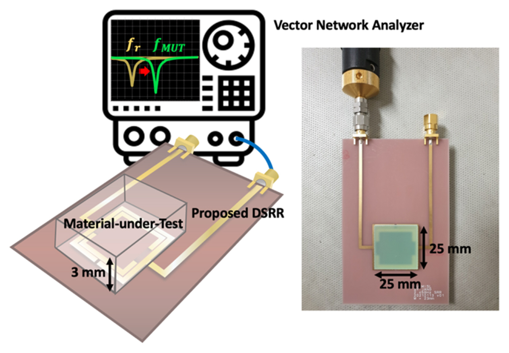
The dielectric constants of the six solid MUTs used in the experiment were measured using certified equipment from the Electromagnetic Wave Technology Institute (EMTI). The MUTs were prepared with the same physical size (25 mm × 25 mm × 3 mm in width × length × height) as the size of the resonant core in the proposed DSRR to minimize the measurement errors of the dielectric constants due to the size differences. Table 1 lists the six solid MUTs and their measured dielectric constants.
The resonant frequency of the MUT on the proposed resonator was determined by measuring the reflection coefficient at one port. The other port of the resonator was terminated by the reference impedance of 50 Ω. The one-port S-parameter measurement was performed from 1 GHz to 3 GHz using a vector network analyzer (VNA). Fig. 5 shows the experimental setup using the proposed DSRR to measure the dielectric constant of solid MUTs.
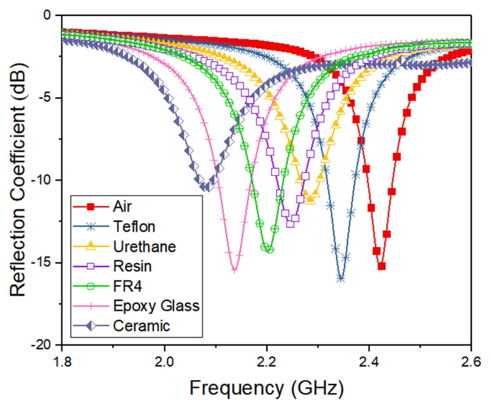
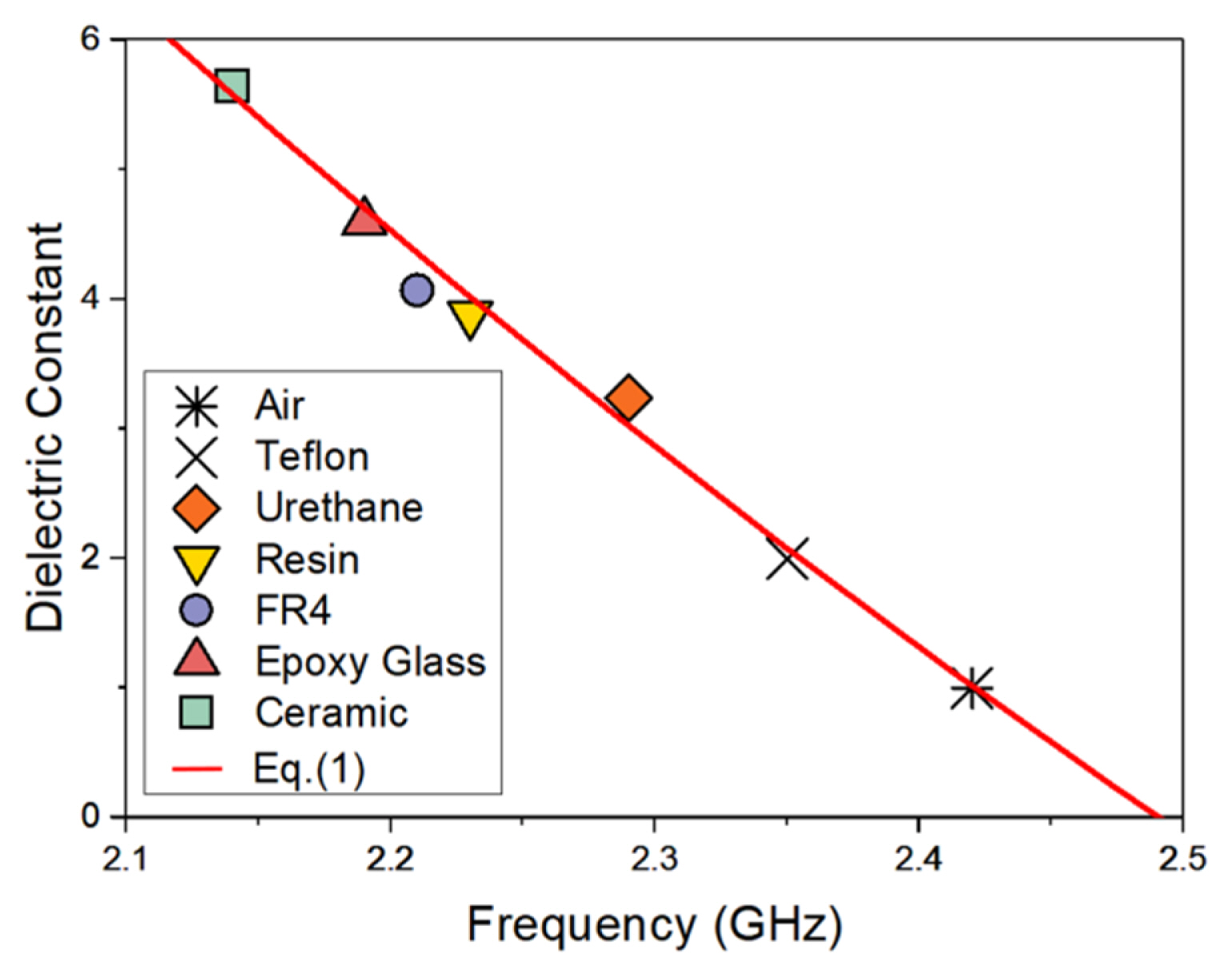
The measurement results of the reflection coefficient in Fig. 6 show that the resonant frequency and the Q-factor vary depending on the MUT. Owing to the dielectric constant of the MUT, the resonant frequency decreases as the capacitance increases. The magnitude of the frequency shift is proportional to the increase in the dielectric constant. The resonant frequencies of the DSRR were measured to be 2.35 GHz in Teflon, 2.29 GHz in urethane, 2.23 GHz in resin, 2.21 GHz in FR4, 2.19 GHz in epoxy glass, and 2.14 GHz in ceramic. The ceramic and urethane MUTs resulted in remarkable decreases in the Q-factor compared to the other MUTs. Fig. 7 shows the correlation between the resonant frequency shifts in the proposed DSRR and the dielectric constants measured using the certified equipment.
A numerical analysis was performed to accurately obtain the correlation between the resonant frequency and the dielectric constant using the measured data shown in Fig. 7. The numerical model for the correlation can be expressed by the following quadratic polynomial equation:
where ɛr_solid is the dielectric constant of the solid MUT and fr is the resonant frequency variance due to the solid MUT. The calculated r2 of Eq. (1), which represents the agreement between the given data and the model equation, is 0.9941, indicating a high correlation between the resonant frequency of the proposed DSRR and the dielectric constant.
The measurement of the dielectric constant using the proposed DSRR and Eq. (1) was validated with two solid MUTs (silicon and rubber) that were not used in the numerical analysis. The dielectric constants measured by the certified equipment and those calculated from the resonant frequencies of the proposed DSRR using Eq. (1) are listed in Table 2. The results show that the dielectric constants can be measured with similar errors using the proposed DSRR and Eq. (1), despite the dielectric constants of the MUTs falling outside the range of data used in the numerical modeling. The calculated dielectric constants are lower than the measured ones because of the voids between the MUTs and the resonator caused by the non-uniformity of the MUT sample surfaces and the resonator. The error rate (ERR) in Table 2, which indicates the percentage difference between the measured and calculated dielectric constants in percentage, is calculated as
where ɛr_meas is the dielectric constant measured using the certified equipment, and ɛr_cal is the calculated dielectric constant obtained from the DSRR and Eq. (1). The detection sensitivity Sd is used as a quantitative performance index for the dielectric constant measurement by resonators operating at the different frequencies and is given by
where fri is the resonant frequency of the resonator with the i-th MUT and ɛri_meas is the dielectric constant of the i-th MUT measured using the certified equipment. The Sd of the proposed DSRR obtained from the eight MUTs is 2.58%.
2. Measurement of Liquid Samples
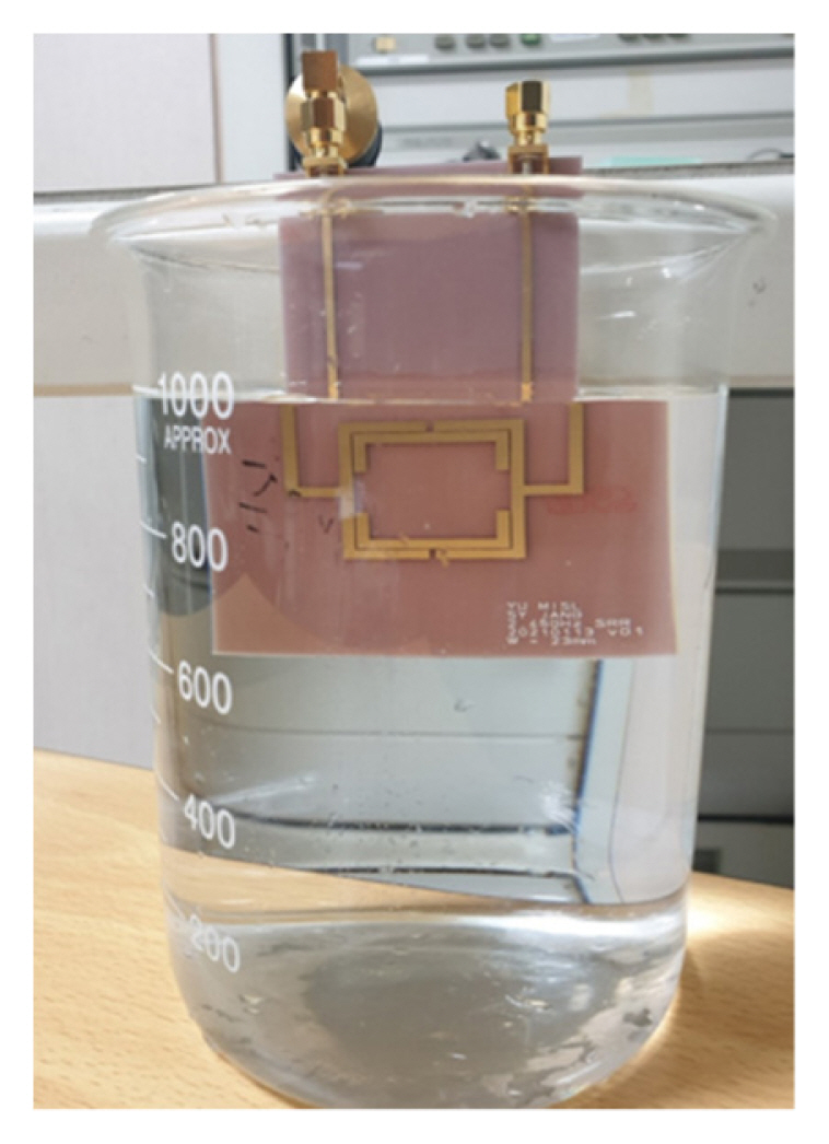
The proposed resonator can be used to measure the dielectric constants of LUTs because of its long input feeding line, as shown in Fig. 8. The resonant core is completely immersed in the liquid, and the feeding line is connected to the VNA outside the liquid. The same volume of 1 L was used for all the LUTs because a 1 L beaker was large enough for the resonator to be sufficiently immersed in the liquids. As in the measurement of solid MUTs, one input port was used to measure the reflection coefficient to determine the resonant frequency, and the other port was terminated with a 50 Ω reference impedance.
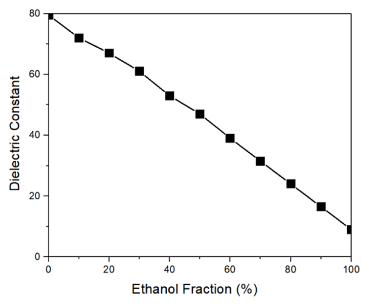
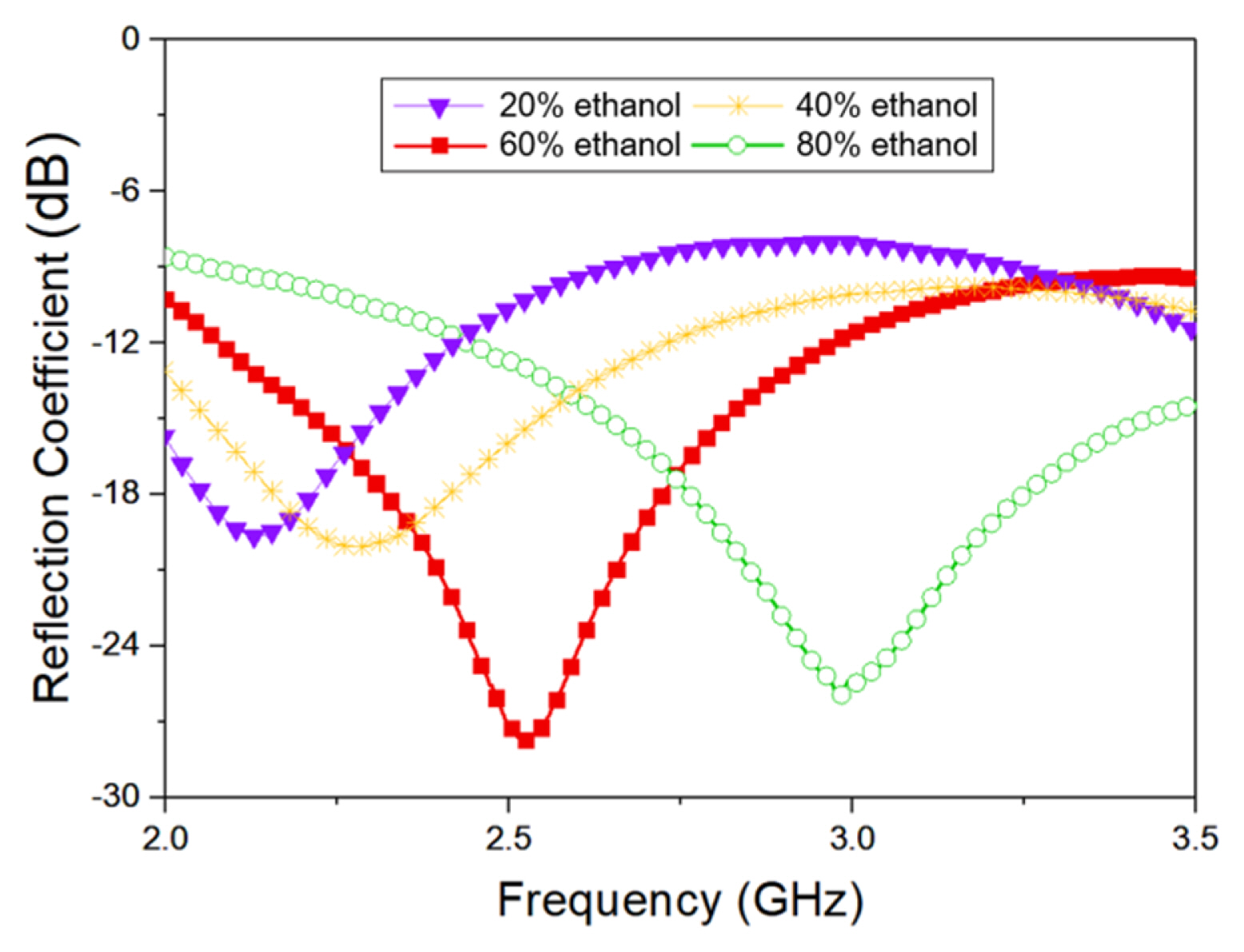
Each LUT sample for the dielectric constant measurement was prepared as an ethanol aqueous solution. The dependence of the dielectric properties of ethanol solutions on the ethanol concentration in several GHz frequency bands has been well studied. The reference based on the data presented in [18] is shown in Fig. 9. Aqueous solutions with ethanol concentrations between 20% and 80% at intervals of 20% for the numerical modeling were prepared by mixing 99.9% ethanol solution with deionized water. As shown in Fig. 10, the resonant frequencies of the DSRR interacting with the 20%, 40%, 60%, and 80% ethanol solutions were measured to be 2.13 GHz, 2.18 GHz, 2.53 GHz, and 2.98 GHz, respectively. The results show that the dielectric constant of deionized water is the dominant factor in determining the resonant frequency of the ethanol solution.
The numerical model for the correlation between the resonant frequency and dielectric constant of the LUTs is expressed by the quadratic polynomial equation
where ɛr_liquid is the dielectric constant of the LUTs. The r2 of Eq. (4) is 0.9463, which indicates that the modeling equation has good agreement with the given data. The dielectric constants of both solids and liquids can be determined using the same modeling formula based on the resonant frequency of the proposed DSRR, but the optimum coefficients of each sample type are required in the modeling equation to obtain accurate measurement results because of the large differences between the range of dielectric constants in the MUTs and LUTs.
Aqueous solutions of 30%, 50%, and 70% ethanol were used to validate the measurement method using the proposed DSRR and Eq. (4). Table 3 shows the measured dielectric constants in [18], the dielectric constants calculated by the proposed method, and the ERRs. The detection sensitivity Sd of the proposed DSRR for liquids obtained from the seven LUTs is 0.3%.
3. Comparison of Dielectric Constant Measurement Methods using Planar-Type Resonators
Table 4 shows a comparison of the dielectric constant measurements reported in previous studies using planar-type resonators with those using the proposed resonator. Despite having a long-feeding line at the input port, the proposed DSRR can measure a wider range of dielectric constants in solid MUTs with a similar Sd as the results of previous studies using SRRs. In addition, the proposed method can measure the dielectric constant in LUTs using the same resonator and modeling formula with a relatively low ERR compared to previous works. The low Sd for the dielectric constants of the LUTs in the proposed method can be attributed to its wide measurement range. The reason for the lower Sd of the LUTs compared to that of the MUTs is that the dielectric constant-dependent resonant frequency shifts are relatively small in liquids [12].
The proposed method using the DSRR shows a lower Sd and higher ERR compared to the results of previous studies using CSRRs, in which the capacitance of the CSRRs is the dominant factor in determining the resonant characteristics. However, measurement methods using CSRRs face the limitation that a microfluidic channel must be formed over the resonator to measure the dielectric constant of a LUT. The proposed method has the advantage that the size of the MUT or the volume of the LUT can be disregarded by placing the MUT on the resonant core or by immersing the resonator inside the LUT.
IV. Conclusion
A DSRR in the 2.45 GHz band is proposed effectively to distinguish and detect dielectric constants in solids and liquids. The two asymmetric splits of the proposed resonator are useful for designing resonant frequencies that can converge to a single frequency to increase the Q-factor. The dielectric constants of solids and liquids are obtained using quadratic polynomial equations numerically modeled with the relationship between the dielectric constant and the resonant frequency. The same formula for the polynomial is used for both solids and liquids, but the coefficients of the polynomials are different because the dielectric constant ranges of the reference materials are quite different, and the coefficients are obtained from numerical modeling. The dielectric constants of silicon and rubber measured using the equation obtained from the resonant frequency shifts of six solid materials are 3.18 and 6.29, respectively, compared to the reference values obtained by certified equipment, which are 3.38 and 6.75, respectively. The equation obtained from the resonant frequency shifts of four samples with different mixing ratios of deionized water and pure ethanol can reflect the dielectric constant for any mixing ratio, with an average error of 2.59%. Sensitivity, defined as the normalized frequency change depending on the dielectric constant, was shown to be 2.58% in solids and 0.30% in liquids. The findings show that the proposed resonator can be used to measure the dielectric constants of both solid and liquid samples over the widest dielectric constant range.