I. Introduction
The electromagnetic field transmission through an aperture or slot in a conducting screen is a canonical and classical problem that has attracted the attention of many researchers. The problem of coupling electromagnetic fields between regions through slots and apertures in conducting planes is commonly encountered in electromagnetic pulse penetration studies and in the area of electromagnetic compatibility. Since Bethe’s work [1] on the small-hole coupling problem was reported, various coupling problems through apertures or slots have been analyzed [2–6]. To our knowledge, the first theoretical study about three-dimensional electromagnetic transmission problems through a rectangular cavity and slot in a thick conducting screen was conducted by Jin and Volakis [7] using the finite element method (FEM). Since then, this problem has been treated by various methods, such as the Fourier transform and mode-matching techniques by Park and Eom [8], the modal expansion method by Cho et al. [9], and a rigorous technique based on the Kobayashi potential method (KPM) [10]. In the field of physics, the extraordinary transmission phenomenon of subwavelength apertures has attracted considerable attention, and many studies have been reported in the field of optics [11–14].
Transmission resonance problems through an aperture or slot mainly deal with the aperture-body resonance (ABR) problem and transmission cavity resonance (TCR) problem. These problems were first treated by Harrington and his colleague [3, 4], who considered the problem of an electrically small aperture in a conducting screen backed by a conducting body using the method of moment (MoM), which is related to the ABR. The transmission problem through narrow slots in thick conducting screens, which is related to the TCR, was also considered by Harrington and Auckland [4].
This study examines electromagnetic energy transmission through a narrow slot in a thick conducting plate when a plane wave is incident to the slot. Previous studies have mainly dealt with the problem of transmission resonance from the viewpoint of equivalent circuits. Conversely, the present study addresses a transmission resonance problem similar to the previous one but from a different perspective that did not use the viewpoint of equivalent circuits. As with other methods [7–10], the integral equation method using MoM with Galerkin’s procedure presented in this paper allows for the exact evaluation of a three-dimensional slot to cavity coupling problems. In addition, the solution presented in this paper uses rigorous kernels to obtain more accurate results. However, as Green’s functions are required, the computational amount increases.
A formulation is used to determine the transmission cross-section (TCS) through thick plate slots. The aperture impedance is also derived to characterize the resonance transmission mode of the thick plate slot. Since the slot in a thick metal plate creates a waveguide structure, it has a cutoff frequency. From the perspective of the cutoff, the resonance transmission characteristics through the slot in a thick conducting screen are classified into three transmission modes: (1) the transmission cavity resonance (TCR) mode for the range above the cutoff, a > 0.5λ, where a is the slot length, and λ is the wavelength; (2) the near-cutoff resonance transmission (NCRT) mode for the range below and near the cutoff, ~0.45λ ≤a< 0.5λ; and (3) the non-transmission cavity (NTC) mode for the range below the cutoff, a< ~0.45λ. The behavior of the TCS and aperture impedance for a thick plate slot is analyzed using the MoM.
The results show that the TCR mode depends on the plate thickness and that peak TCSs appear periodically along the plate thickness, which is known as Fabry-Perot resonance. The NCRT mode depends on the slot length and plate thickness, and the maximum TCS appears only once as a slot length resonance (or transverse resonance), which comes from the coupled resonance by the slot length and plate thickness. The peak TCS for the NCRT mode occurs with a thin plate thickness, which produces slot length resonance. The NTC mode is a non-transmission and non-resonance mode and is not transmitted. Therefore, the TCS decreases exponentially with an increase in plate thickness, and resonance transmission could not be realized in the NTC mode. In particular, all the maximum TCSs for the TCR and NCRT modes occur in parallel resonance, which can be confirmed by the behavior of the aperture impedance. The analysis results show that a good understanding of the resonance transmission modes through the behavior of the TCS and aperture impedance should be taken into account.
II. Problem Formulation
Fig. 1 shows the geometry and coordinate system of a thick conducting plane with a narrow slot. The thick conducting ground plane has a thickness d and is located in the xy-plane, with the origin at the center of the slot aperture S1. The slot aperture S2 is in the xy-plane separate from the slot aperture S1 at a distance z = d. The narrow slot has a length of a and a width of b. A thick conducting wall is a perfect electric conductor.
As shown in Fig. 1(a), the thick conducting plate structure is divided into three regions: a half-space containing the incident plane wave (Region I (z<0)), an interior region comprising the two slot apertures (Region II (0<z<d)), and a half-space comprising the penetrating field (Region III (z>0)). These three regions are assumed to be free-space regions.
If the plane wave is incident to the narrow slot in the thick metallic ground plane, the following is required to ensure the continuity of the tangential components of the magnetic fields across the slot aperture, as shown in Fig. 1(b):
where
H ¯ i j I , I I , I I I ( i , j = 1 o r 2 ) M ¯ 1 ± = ∓ z ^ × E ¯ a 1 M ¯ 2 ± = ∓ z ^ × E ¯ a 2
From (1), the simultaneous integral equations for the unknown magnetic currents in the slot can be written as follows:
(2a)
(2b)
where
k 0 = ω ɛ 0 μ 0 I ¯ ¯ E 0 y i G ¯ ¯ i j h I , I I I G ¯ ¯ i j h I I
(3)
where ɛ0n=1 for n = 0 and 2 for z≥1, and x1=a/2, y1=b/2, z1=0, and z2=d. The waveguide propagation constant is given by
To solve the simultaneous integral equations for the unknown magnetic currents, the aperture electric fields in slots Ēa1 and Ēa2 are expanded as follows:
where V1p and V2q are the coefficients to be determined, and Fp(x) and Fq(x) are piecewise sinusoidal functions. The y-directional variation of the aperture electric field is given as follows [2]:
III. Transmitted Power and TCS
When a plane wave excites narrow slot S1, the time average power transmitted from Region I to Region III through slot S2 is expressed as follows:
where the asterisk denotes a complex conjugation. The transmission coefficient (TC) through a small, narrow slot S2 is defined as follows:
where Pinc is the average incident power intercepted by the narrow slot S1. For an incident plane wave,
where A is the area of aperture S1, and
H O x i
When a plane wave excites a narrow small slot, the TCS of the narrow small slot is defined as the area where the incident wave contains the power transmitted by the narrow small slot. It follows that the TCS is equal to TC·A.
If the thin dipole or narrow slot resonates near half the wavelength, then the TCS becomes 3.28λ2/4π (= 2Gλ2/4π, G = 1.64). For a small, electrically thin antenna, the maximum absorption area (TCS) is equal to 3λ2/4π (= 2Gλ2/4π, G = 1.5). It is also a Hertzian source.
To investigate the resonance transmission through the thick plate slot, the slot aperture impedance with the TCS is also calculated to find the resonance state as follows:
where
This study focuses on the TCS problem in which all three regions are free-space regions.
IV. Results and Discussion
To validate the theoretical analysis method, some numerical results obtained through this method are compared with the results of Reed and Butler [6] for the narrow slot with d = 0.001λ, Jin and Volakis [7], and Serizawa [10], as shown in Fig. 2(a) and (b). The comparison shows good agreement. Fig. 2(b) shows a slight difference for a> ~0.55λ, but this is due to the fact that the solution presented in the paper is for narrow slots.
1. Resonance Transmission Modes through a Thick Plate Slot
Fig. 3 presents the TCS characteristics versus the slot length as a parameter of various thicknesses of a conducting plate. Resonance transmission occurs above and near the cutoff frequency for a plate thickness, but the TCS is rapidly attenuated below the cutoff frequency. In general, the propagation of electromagnetic energy does not occur below the cutoff frequency, but maximum transmission can occur for plate thicknesses of d = 0.01λ, 0.25λ, and 0.10λ near the cutoff, as shown in Fig. 3(a). Even if the frequency is below the cutoff, maximum transmission (enhanced resonance transmission) occurs. This phenomenon occurring near the cutoff is a very interesting topic. It is necessary to find near the cutoff boundary, which can be obtained by considering the conditions under which the maximum transmission occurs in a very thin plate. As shown in Fig. 3(b), for a relatively thin plate with d=0.1λ, the TCS peak occurs at a=0.486λ, but in the case of a very thin plate such as d=0.001λ, the maximum TCS occurs at a=0.456λ. Therefore, a=0.456λ can be seen as the transition boundary near the cutoff. Accordingly, the region below and near the cutoff can be determined as ~0.45λ≤a<0.5λ. The plate thickness is related to the classification of the transmission mode and is particularly important in determining the existence of the NCRT mode.
As shown in Fig. 3, the results can be classified into three categories, and accordingly, three different transmission types of TCS patterns appear: (1) the pattern above the cutoff (a > 0.5λ), (2) the pattern near the cutoff (~0.45λ ≤ a < 0.5λ), and (3) the pattern below the cutoff (a≤~0.45λ), which are called the TCR mode, NCRT mode, and NTC mode, respectively. To further understand the behavior of resonance transmission, aperture impedance is also calculated. Both TCS and aperture impedance characteristics are used to investigate the classification of resonance transmission phenomena through a slot in a thick conducting screen.
1) TCR mode
Fig. 4 shows the TCS versus the thickness of a conducting plate as a parameter of various slot lengths. When the slot length is greater than the cutoff (i.e., for a>0.5λ), the traveling electromagnetic wave is in Region II (waveguide region or transmission cavity region), and the TCS fluctuates with the plate thickness, with a fluctuation period of approximately 0.7λ, as shown in Fig. 4. The maximum TCSs occur periodically at d=0.64λ and d=1.35λ, which are known as resonance transmission (enhanced resonance transmission). In this case, the magnetic wall reflections at slot apertures S1 and S2 make a Fabry-Perot resonance pattern along the plate thickness (i.e., the longitudinal direction, z-direction) from the multiple reflections in both slots. This type of resonance transmission mode is called the TCR mode by Harrington and Auckland [4] and Cho et al. [9]. In addition, small peak TCSs are observed at d = 0.32λ, d = 1.03λ, and d = 1.35λ due to the effects of slot width. The magnitude of the TCS becomes even smaller as the slot width narrows.
Fig. 5 shows the aperture impedance and TCS characteristics versus the plate thickness for a=0.7λ (above the cutoff), 0.47λ (below and near the cutoff), and 0.45λ (below the cutoff). Above the cutoff, the TCR mode occurs at parallel resonances from a plate thickness with d=0.64λ and d=1.35λ, as shown in Fig. 5(a). The other parallel resonances result in small peak TCSs compared to the maximum TCSs. These small peak TCSs are due to the real part of the aperture impedance being larger than that of the maximum TCSs. Thus, a large aperture resistance creates small reflections in both slots; thus, the TCS becomes relatively small compared to the maximum TCS. Parallel resonance characteristics (with a change in reactance from inductive to capacitive) occur in the frequency characteristics of the aperture impedance, as will be shown later in Fig. 9. The thickness characteristics of the aperture impedance in Fig. 5 seem to have series resonance (a change in reactance from capacitive to inductive), but resonance can be discriminated from the frequency characteristics of the aperture impedance, as shown in Fig. 9.
2) NCRT mode
When the slot length is below and near the cutoff (i.e., for a=0.47λ), the traveling electromagnetic wave is not in Region II (waveguide region) because the slot length is below the cutoff. Nevertheless, one maximum TCS appears with a very thin plate thickness of d=0.024λ, as shown in Fig. 5(b). This is due to the reflections in both slot apertures S1 and S2 exciting the slot length, which can result in transverse resonance through the coupling of the plate thickness along the z-direction. This transverse resonance of the slot occurs from the reflections in both slot apertures as a parallel resonance excited by the incident plane wave. The reflection is caused by the transverse excitation of the slot along the transverse direction (x-direction). Thus, in this case, a peak TCS due to slot length resonance (i.e., x-directional transverse resonance) can be obtained from the thin plate thickness, resulting in reflections in both slot apertures.
As a result, when the slot length is below and near the cutoff, only one maximum TCS appears, with a thin plate thickness as a parallel resonance. This type of resonance transmission mode is defined in this study as the NCRT mode. The NCRT phenomena are only observed when the slot length is below and near the cutoff with a thin plate thickness because the plate thickness causes slot length resonance. In addition, the slot length of a=0.45λ may be considered a boundary reference length, which determines what is below and near the cutoff (see Fig. 7(b) in Section IV-2).
3) NTC mode
When the slot length is below the cutoff (i.e., for a = 0.45λ), the traveling electromagnetic wave is not in Region II (waveguide region) because the slot length is below the cutoff. In this case, the TCS rapidly attenuates exponentially along the longitudinal direction (z-direction), as shown in Fig. 5(c). Therefore, reflections do not occur in either slot aperture, and slot length resonance (x-directional transverse resonance) cannot occur with plate thickness. This type of transmission mode is called the NTC mode. The NTC mode corresponds to a non-transmission mode. As electromagnetic transmission power rapidly attenuates exponentially along the waveguide region (Region II), reflections do not occur in either slot aperture, and thus resonance transmission does not occur.
2. Classification of Resonance Transmission Modes through a Thick Slot
We investigate the mode classification of the resonance transmission phenomena through a narrow slot in a thick conducting screen using the TCS and an aperture impedance. As discussed previously, there are three types of resonance transmission modes through a thick plate slot, as shown in Fig. 6. The three types of transmission modes are classified according to the cutoff criterion: (1) above the cutoff, (2) below and near the cutoff, and (3) below the cutoff. These are summarized as follows:
-
TCR mode
Above the cutoff (a>0.5λ, -
NCRT mode
Below and near the cutoff (~0.45λ≤a<0.5λ, -
NTC mode
Below the cutoff (a≤~0.45λ,
As mentioned in Section IV-1, the TCR mode above the cutoff occurs mainly with a plate thickness as a parallel resonance, which is called the Fabry-Perot resonance, from the multiple reflections in both slot apertures. By contrast, below and near the cutoff, the NCRT mode is a very interesting subject because one maximum TCS occurs with a thin plate thickness as a parallel resonance. In this case, a peak TCS can be obtained from the slot length resonance (x-directional transverse resonance) from the coupling of the plate thickness. The NTC mode below the cutoff corresponds to a non-transmission and non-resonance mode, and electromagnetic transmission power rapidly attenuates exponentially along the waveguide region. As a result, the peak TCSs for the TCR and NCRT modes are of the parallel type, which leads to high slot aperture fields.
In addition, the slot length boundary determining the area below and near the cutoff can be determined according to whether one resonance transmission (maximum TCS) or slot length resonance (transverse resonance) can be obtained. Fig. 7(a) shows the TCS versus the thickness of a conducting plate as a parameter of various slot lengths below the cutoff (i.e., 0.40λ≤a< 0.49λ). Peak TCSs appear above a=0.45λ. To understand the peak TCSs, the aperture impedance characteristics are necessary, as shown in Fig. 7(b). The peak TCS (25.95 cm2) for a=0.46λ occurs when the aperture reactance becomes zero at d=0.006λ. The peak TCS corresponds to resonance transmission or maximum transmission and is obtained at parallel resonance. In comparison, there is no resonance for a=0.45λ, and there is no resonance transmission. Therefore, a slot length of 0.45λ can be regarded as a boundary criterion for a slot length determined as below and near the cutoff. The area near the cutoff region can be defined as ~0.45λ≤a<0.5λ, and the NCRT mode is observed only at ~0.45λ≤a<0.5λ.
3. Frequency Characteristics of TCS and Aperture Impedance
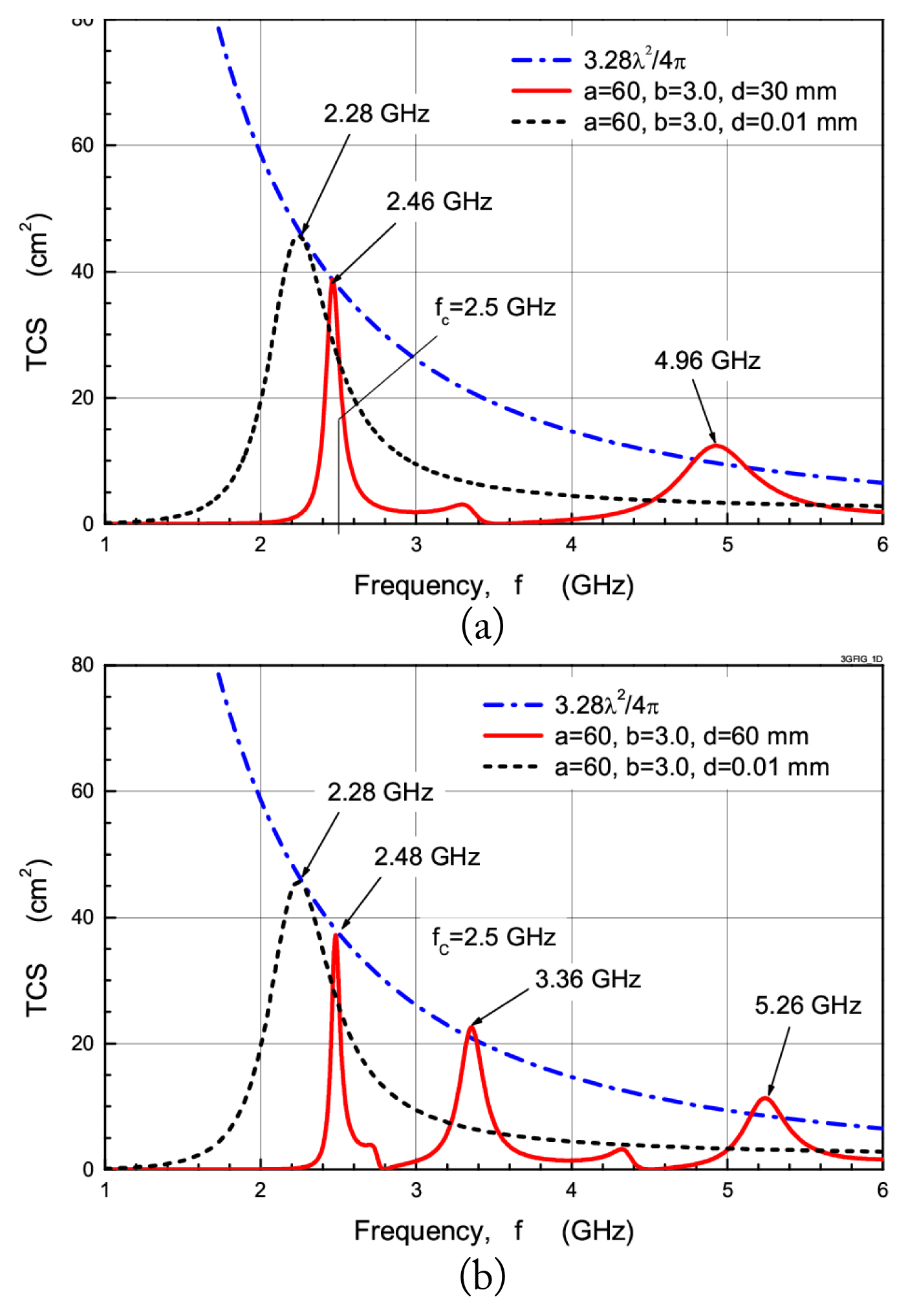
Fig. 8 shows the frequency characteristics of the TCS for a thick plate with a narrow slot excited by an incident plane wave for the following three cases:
In Fig. 8(a) and 8(b), the dashed line represents the TCS in Case 1, which shows one TCS peak at 2.28 GHz. In Fig. 8(a), the solid line represents the TCS in Case 2, which shows two TCS peaks at frequencies of 2.46 GHz and 4.96 GHz. In Fig. 8(b), the solid line represents the TCS in Case 3, which shows three TCS peaks at frequencies of 2.48, 3.36, and 5.26 GHz. The desired maximum TCS for a narrow slot in a thin conducting plate is 3.28λ2/4π (= 2Gλ2/4π, G = 1.64), which is the TCS for the resonant slot near the half-wavelength. For the three cases, the peak TCSs of the thick plate slot reach the desired maximum TCS (3.28λ2/4π), which is represented by a dashed dot line.
As narrow slots may behave like a lossy magnetic wall, this type of transmission peak is observed only when a lossy cavity is formed along the plate thickness direction. Case 1 corresponds to a thin conducting screen, as expected from a resonant slot, in which the reactive part of the aperture impedance can be tuned to zero by creating slot length resonance (transverse resonance) from a thin plate thickness. This peak TCS occurs at slightly less than half the wavelength. For Case 1, the peak TCS at 2.28 GHz (a=0.456λ and d=0.76×10⁻⁴λ) is in the NCRT mode (i.e., ~0.45λ≤a<0.5λ and
Γ 10 I I = α 10
As shown in Fig. 8(a), for Case 2, the peak TCS at 2.46 GHz (a=0.492λ) is in NCRT mode, while the peak TCS at 4.96 GHz (a=0.992λ) is in the TCR mode (i.e., a>0.5λ and
Γ 10 I I = j β 10
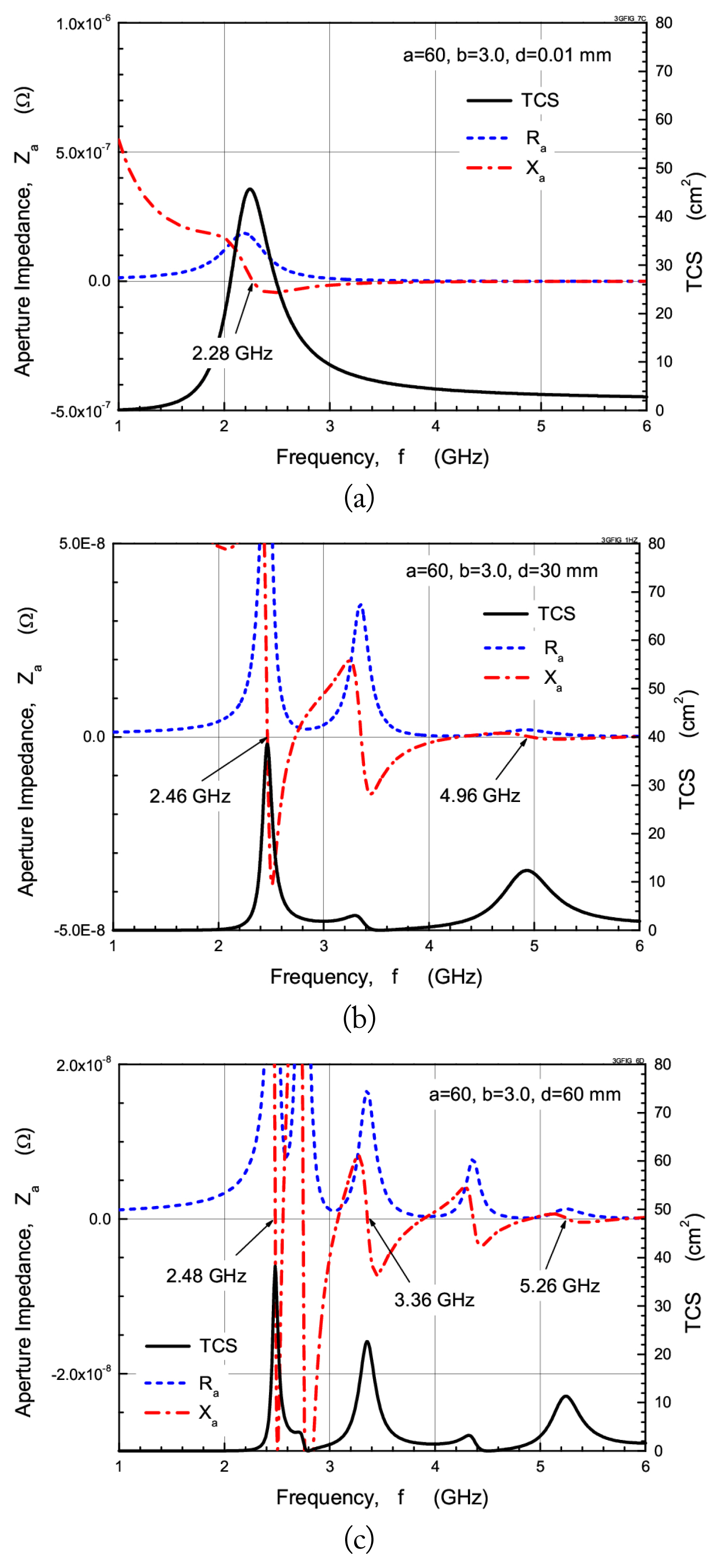
Fig. 9 shows the aperture impedance and TCS characteristics versus the frequency of a thick plate slot excited by an incident plane wave for Cases 1, 2, and 3. The analysis results show that all peak TCSs (2.28 GHz for Case 1, 2.46 and 4.96 GHz for Case 2, and 2.48, 3.36, and 5.26 GHz for Case 3) are obtained at parallel resonance, as shown in Fig. 9. Series resonance does not contribute to resonance transmission because radiation resistances are very small at the series resonance. In other words, series resonance does not contribute to radiation from the slot aperture. The TCS and aperture impedance characteristics of Case 1 are similar to those of a narrow slot in a thin conducting plate (zero-thickness case). The analysis results show that all peak TCSs occur in parallel resonance, as in the case of a thin plate slot.
V. Conclusion
Three types of transmission modes through a narrow rectangular slot in a thick conducting screen are considered using the behavior of the transmission TCS and aperture impedance. For the transmission mode through a thick plate slot, the coupled integral equations in the aperture magnetic fields are derived and solved by applying Galerkin’s MoM, from which the TCS and aperture impedance are calculated. Three types of transmission modes are classified for a better understanding of transmission characteristics through a thick plate slot.
For the TCR mode above the cutoff, Fabry-Perot resonance occurs from the multiple reflections in both slot apertures. In the NCRT mode below and near the cutoff, slot length resonance coupled with plate thickness occurs; thus, resonance transmission occurs when the screen thickness is relatively thin. A decayed electromagnetic field is observed below the cutoff; thus, resonance transmission does not occur in the NTC mode. In addition, all the maximum TCSs for the TCR and NCRT modes are of the parallel type, which leads to high slot aperture fields. The analysis results show that a good understanding of resonance transmission modes in the behavior of the TCS and aperture impedance should be taken into account.