Radiation from a Millimeter-Wave Rectangular Waveguide Slot Array Antenna Enclosed by a Von Karman Radome
Article information
Abstract
In this paper, electromagnetic radiation from a slot array antenna enclosed by a Von Karman radome is analyzed by using the ray tracing method and Huygens’s principle. We consider the rectangular slot array antenna and the Von Karman radome. The radiation patterns are calculated by using the surface currents of the radome to illustrate the electromagnetic behaviors of the radome-enclosed waveguide slot array antenna.
I. Introduction
Radomes are widely used to protect antennas from their physical environment. As they distort the transmitted and received radar signals, they require electromagnetic analysis. Extensive studies have been conducted on the electromagnetic characteristics of radomes [1–14]. Ray tracing and physical optics (PO) method were suggested to analyze radomes [1]. Curved radomes enclosed in a single-element antenna were analyzed by using various methods [2–7]. The radiation pattern of a hemisphere radome fed from a circular aperture was calculated by using the dyadic Green’s function technique/PO method [2] and the aperture integration-surface integration (AI-SI) [3]. The electromagnetic characteristics of the frequency selective surface tangent-ogive radome-enclosed antenna were analyzed using ray tracing and Huygens’s principle [4]. The electromagnetic properties of the Von Karman radome-enclosed dipole antenna were analyzed by using the method of moments (MoM) [5] and coupled surface integral equation [6]. The radiation pattern of the Cassegrain monopulse antenna covered with a multilayered Von Karman radome was also analyzed by using the AI-SI [7]. The scattered fields of the Von Karman radome were calculated by using the MoM [8]. The radiation pattern of the conformal load-bearing antenna structure was calculated using the ray tracing–surface integration [9]. The boresight error (BSE) induced by a gimbal angle is analyzed by using the ray tracing technique [10]. Moreover, curved radomes enclosed by multiple sources were investigated using various analysis techniques [11–14]. The transmission through the radomeenclosed multiple sources was examined by using the multilevel fast multipole algorithm [11]. The hemisphere radome with a metallic cap was analyzed by using the time-domain finite integration theorem [12]. A tangent-ogive radome with a metallic cap was examined using the iterative PO (IPO)–boundary integral–finite element method (FEM) [13]. The radiation properties of dipole arrays enclosed by the Von Karman radome were analyzed by using the IPO scheme [14]. However, the analysis of the hundreds of slot antennas enclosed by Von Karman radome based on an actual model was not presented. In this paper, we use the results of [15] for a waveguide array antenna with hundreds of rectangular slots and analyze the electromagnetic radiation from the antenna enclosed by a Von Karman radome based on the ray tracing technique and Huygens’s principle. Our method is known to be numerically more efficient than the full-wave analysis or the IPO scheme. The rays from each slot are traced and the electromagnetic fields on the outer surface of the radomes are calculated by Huygens’s principle. The radiation patterns are computed by using the surface currents on the outer surface of the radome to understand the electromagnetic characteristics of the radome-enclosed waveguide slot array.
II. Field Analysis
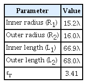
The waveguide slot array antenna enclosed by a Von Karman radome is shown in Fig. 1. The waveguide array antenna has 112 elements [15]. The dielectric constant of the radome and tilt angle are ɛr and αx. The shape of the Von Karman radome satisfies the following equations in the cylindrical coordinates.

Waveguide slot array antenna enclosed by a Von Karman radome.
where Li, Ri, and t are the ith radome surface length, radius, and intervening variable, respectively. Fig. 2 illustrates the analysis procedure of the radome-enclosed waveguide slot array antenna based on the ray tracing and Huygens’s principle.

Analysis procedure of the radome-enclosed waveguide slot array antenna.
The waveguide slot array antenna based on an actual model [15] has 112 elements and the electric fields of the slots are obtained by the simulation of the ANSYS High Frequency Structure Simulator (HFSS) based on the 3D FEM (Fig. 3). Details on how to design the antenna can be found in [15]. We assume that the point source is at the center of each slot. Using the surface equivalence theorem [16], the magnetic currents on the slot are given by

Electric field of the rectangular slots.
where n̂ is the normal vector of the slot and

Mesh and ray generation.
where tρ and tz are the horizontal and vertical components of the tangential vectors, respectively. At the intercept point, the incident fields are split by the perpendicular and parallel components. The reflected and transmitted waves are obtained by using the reflection and transmission coefficients of each polarization. On the outer radome surface, we enforce Huygens’s principle to calculate the radiation pattern of the Von Karman radome-enclosed slot array antenna [4]. We use the far-field approximation [15] to calculate the radiated fields from each radome mesh as
where A(m, n) is the surface area of each mesh as
where, L2 and R2 are the length and the radius of the Von Karman radome, respectively. The radiated power can be obtained from the Poynting vector (P⃗) as
where E⃗ and H⃗ are the radiated electromagnetic fields at the observation points.
III. Numerical Results
To check the validity of our analysis, we consider the radome with a dielectric constant (ɛr) of 1, which means (that the array has no radome). Fig. 5 illustrates the radiation pattern of the Von Karman radome-enclosed waveguide slot array antenna designed for the Ka-band. We compare our calculated result with the radiation pattern of the slot array antenna. As the mesh number increases to 400 × 400, the results of the ray tracing technique and the case of the slot antenna without a radome show a good agreement. Note that the mesh size should be less than λ/4 (Table 1).
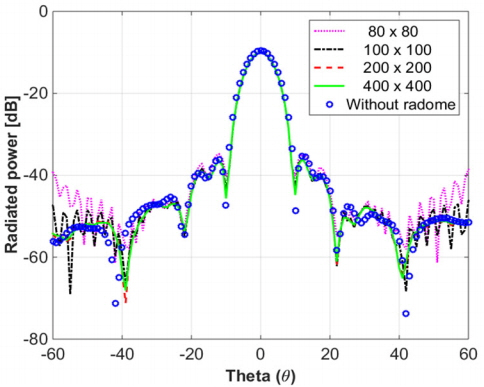
Radiation pattern of the radome-enclosed waveguide slot array antenna (ɛr = 1).
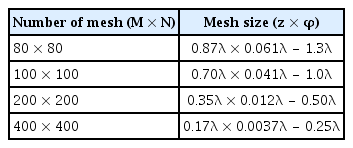
Number of mesh and mesh size (outer surface)
Fig. 6 shows the radiation pattern of the Von Karman radome-enclosed waveguide slot array antenna for the different gimbal tilt angles (αx). The design parameters of the radome are presented in Table 2, and Table 3 shows the transmission loss of the radome. Two possibilities can account for the gain reduction. The transmission loss and the sidelobe level decrease as the tilt angle increases because of the enhancement of reflection loss at smaller incident angles. Note that the image robes are observed at nearly θ = −40° in Fig. 6 because of the internal reflection within the radome. Fig. 7 illustrates the surface currents of the radome for the different gimbal tilt angles (αx). Large current distributions can be seen near the each tilt angle and the angle of the image robe.
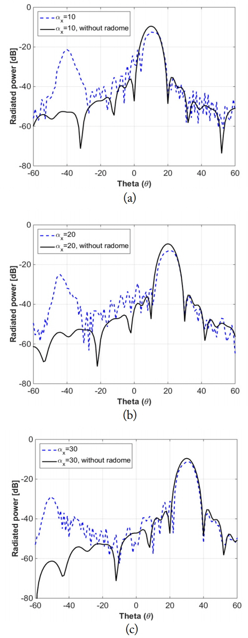
Radiation pattern of the radome-enclosed waveguide slot array antenna. (a) αx = 10°, (b) αx = 20°, and (c) αx = 30°.

Transmission loss and the sidelobe level of the Von Karman radome-enclosed waveguide slot array antenna
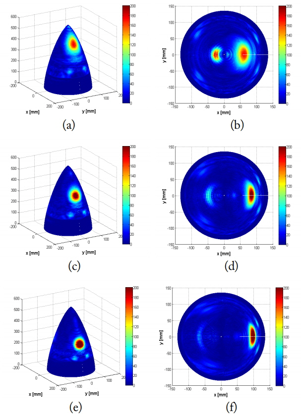
Surface current of the radome. (a) αx = 10° (side view), (b) αx = 10° (top view), (c) αx = 20° (side view), (d) αx = 20° (top view), (e) αx = 30° (side view), (f) αx = 30° (top view).
IV. Conclusion
We have analyzed the electromagnetic radiation from a slot array antenna enclosed by a Von Karman radome using the ray tracing technique and Huygens’s principle. The radiation patterns of the radome-enclosed waveguide slot array antenna were calculated to illustrate the electromagnetic behaviors of the radomes. Our method is useful to estimate the electromagnetic characteristics, such as the radiation patterns and the BSE, of the radome-enclosed waveguide slot array antenna.
Acknowledgements
This work was supported by Hanwha Systems.
References
Biography
Jihyung Kim obtained his B.S. and M.S./Ph.D. degrees in electrical engineering from Ajou University, Suwon, Korea, in 2009 and 2016, respectively. Since 2016, he has been a researcher at Hanwha Systems. His research interests include the analysis of aperture array antennas and radomes.

Hokeun Shin received his B.S. degree in electrical and computer engineering from Ajou University, Suwon, Korea, in 2015. He is currently undertaking his M.S. and Ph.D. course at the Department of Electrical and Computer Engineering, Ajou University, Suwon, Korea. His research interests include the analysis of radomes and radar cross section.

Sung Chan Song obtained his B.S. and M.S. degrees in avionics engineering from Korea Aerospace University, Goyang, Korea, in 2001 and 2003, respectively. From 2002 to 2015, he worked at Samsung Thales. Since 2015, he has been a researcher at Hanwha systems. His research interests include antennas, electromagnetic wave numerical analysis, and radar systems.

Yong Bae Park received his B.S. (summa cum laude), M.S., and Ph.D. degrees in electrical engineering from the Korea Advanced Institute of Science and Technology (KAIST), Daejeon, Korea, in 1998, 2000, and 2003, respectively. From 2003 to 2006, he was with the Korea Telecom Laboratory, Seoul, Korea. In 2006, he joined the School of Electrical and Computer Engineering, Ajou University, Suwon, Korea, where he is currently a professor. His research interests include electromagnetic field analysis and electromagnetic interference and compatibility.
