I. Introduction
Mobile and wireless communication technologies have developed rapidly in order to satisfy the growing demands for high-capacity and high-speed data transmission. The transmission of a high quality signal to a receiver within telecommunication systems requires base stations that generate cell coverage. The coverage area is defined as the total area within the reach of the signal. However, in cities with many obstacles, communication quality can be degraded at cell edges. Such obstacles include shadowed areas, tunnels, and buildings. To improve the communication quality and to extend the coverage area with effective cost, a repeater system is necessary in modern communication systems [1].
Microstrip patch antennas are commonly used in repeater applications because of low production cost, easy fabrication, light weight, and their low profile. However, a typical microstrip patch antenna has a narrow bandwidth. Thus, several methods have been introduced to widen the bandwidth using different types of feed structure [2ŌĆō6]. Commonly used feeding methods to enhance the bandwidth include: the coplanar waveguide-fed (CPW) technique [2], a U-shaped feed [3, 4], a probe feed with a W-shaped ground [5], and an L-probe feed [6], which enhance the bandwidth by up to 25%. However, these antennas cannot cover Global System for Mobile Communications (GSM-1800), Personal Communications Service (PCS), and the Universal Mobile Telecommunication System (UMTS) [7] frequency bands, simultaneously.
To overcome this problem, we propose a low-profile broadband 1 ├Ś 4 array antenna for home repeater applications. The proposed antenna uses the gap feeding between the patch elements and feeding strip to achieve the wide bandwidth characteristic [8]. In order to decrease the mutual coupling without increasing the physical separation between patch elements, slits are added to ground plane 1 [9]. The antenna has a wide bandwidth (1.67ŌĆō2.32 GHz) covering the GSM-1800 (1.71ŌĆō1.88 GHz), PCS (1.85ŌĆō1.99 GHz), and UMTS (1.92ŌĆō2.17 GHz) frequency bands. FR-4 substrate 2 with ground plane 2 (GND2) is located under the bottom of substrate 1 as a reflector, which makes the radiation pattern unidirectional with a high gain level over the operating frequency band.
II. Antenna Design
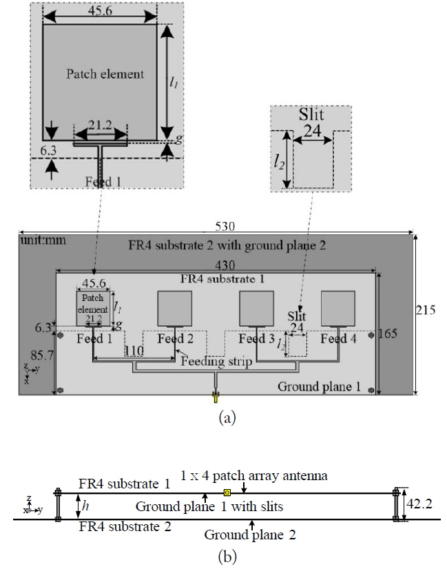
Fig. 1 shows the geometry of the proposed antenna. The proposed antenna was designed on an FR-4 substrate (╔ør = 4.4, tan╬┤ = 0.02), 1 ├Ś 4 array antenna with a separation distance between the adjacent elements of 110 mm. Each antenna element is excited by a feeding strip located on the upper side of the FR-4 substrate 1. A multi-resonance characteristic was achieved by using the gap feeding between the patch element and feeding strip [8]. The ground plane 1, with dimension of 85.7 mm ├Ś 430 mm, is located on the bottom side of the FR-4 substrate 1. To improve the isolation characteristics between the antenna elements, slits were added to ground plane 1. As shown in Fig. 1(a), the optimal length l1 of the patch element, and the gap g between the patch element and feeding strip, are 46 mm and 0.3 mm, respectively. The dimensions of the Fr-4 substrate 1 and 2 are, respectively, 430 mm ├Ś 165 mm and 530 mm ├Ś 215 mm with a thickness of 0.8 mm. To improve the gain and front-to-back ratio (FBR) of the proposed antenna, substrate 2 is placed 32.4 mm away from the bottom of substrate 1. Metal bolts and nuts were used to fix substrate 1 and 2 with a height of 42.4 mm.
III. Simulated Results and Analysis
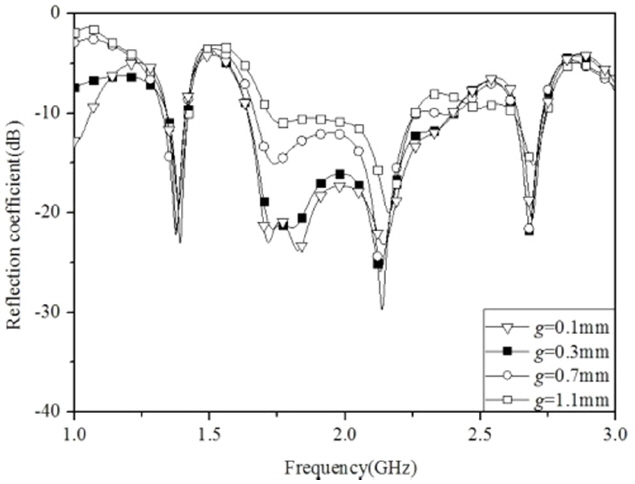
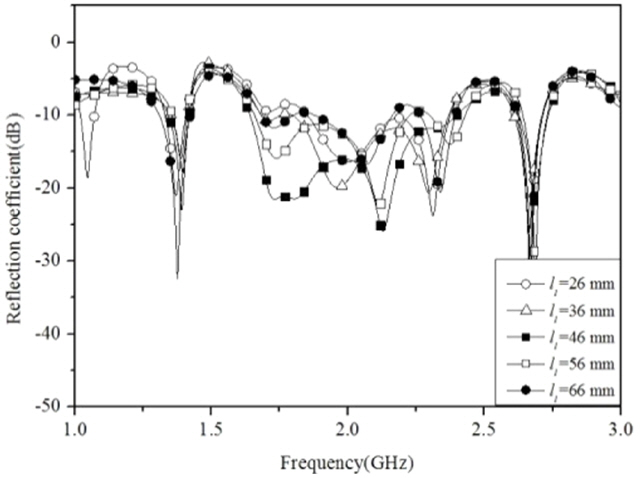
In order to analyze the effect of the gap feeding, the reflection coefficients of the proposed antenna and direct-fed antenna were compared, and the results are shown in Fig. 2. The direct-fed antenna has the same basic structure as the proposed antenna with the exception of feeding structure. By using gap feeding, impedance matching is improved and the ŌłÆ10 dB reflection coefficient bandwidth simultaneously covers the GSM-1800 (1.71ŌĆō1.88 GHz), PCS (1.85ŌĆō1.99 GHz) and UMTS (1.92ŌĆō2.17 GHz) bands. Simulation results were analyzed using an ANSYS High-Frequency Structure Simulator (HFSS) version 17.2 (ANSYS Inc., Canonsburg, PA, USA). Fig. 3 shows the simulated reflection coefficients when the gap g between the patch element and feeding strip changed from 0.1 mm to 1.1 mm. It showed that as g decreases, the bandwidth of the antenna increases. This is especially important for PCS and UMTS bands that are critically affected by g. When g was equal to 0.3 mm, the antenna had a wider ŌłÆ10 dB reflection coefficient bandwidth than that observed for gaps of 0.7 mm or 1.1 mm. As the change in reflection coefficient bandwidth is negligible when the value of g is less than 0.3 mm (i.e., 0.1 mm), 0.3 mm is the optimized value of g for easy fabrication. Fig. 4 illustrates the simulated reflection coefficients for various values of length l1. A change in the l1 value affects the resonance frequency and reflection coefficient. As l1 decreased, the entire frequency band was shifted to the higher frequency side, whereas when the value of l1 increased, the resonance frequency was shifted to the lower frequency side. Optimum performance was achieved when l1 was equal to 46 mm.
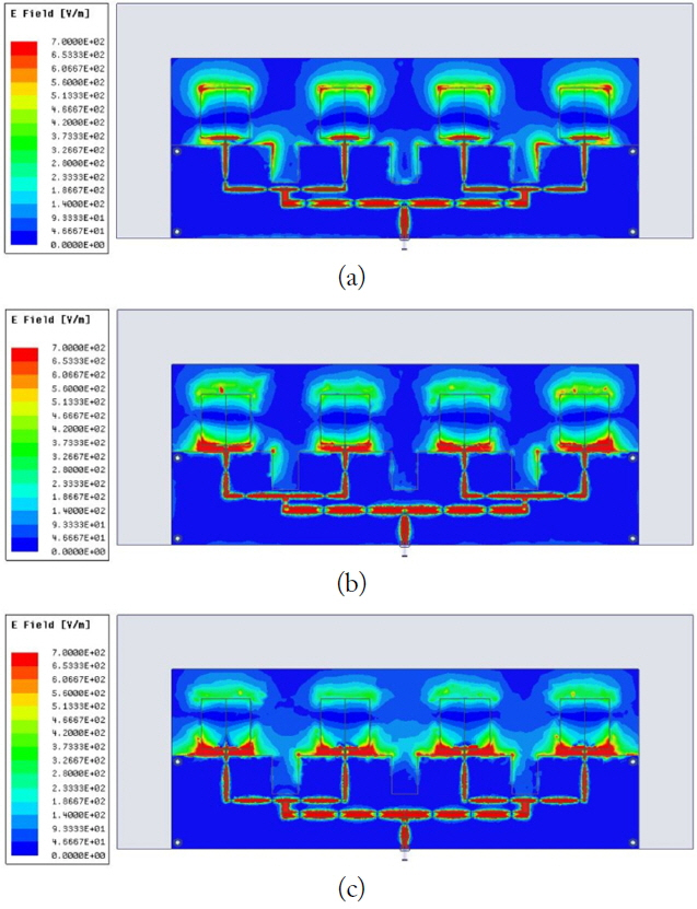
In order to analyze the operational characteristics of the proposed antenna, the simulated electric field distributions on the antenna were analyzed as shown in Fig. 5. In Fig. 5(a), the proposed antenna is operating at 1.755 GHz because each patch element has an effective electrical length of ╬╗/2. Fig. 5(b) and (c) show that the antenna operates at 1.97 GHz and 2.16 GHz because of the coupling between the patch elements and the ground plane.
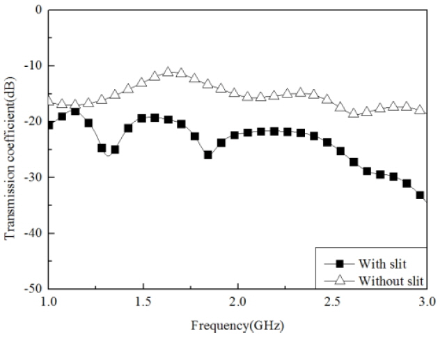
In general, it is required that be sufficient space between patch elements in order to obtain a high isolation level [10]. However, a physical space that is too large can affect radiation performance, resulting in an increase of the side-lobe level and a decrease in peak gain [11, 12]. By adding slits in the ground plane, the physical size of the antenna can be reduced and the mutual coupling between antenna elements decreases. The transmission coefficients of the proposed antenna with and without slits are compared in Fig. 6. Both antennas have the same structure, the only difference between them being the presence or absence of slits.
The isolation level of ŌłÆ20 dB is realized over the entire operating frequency band.
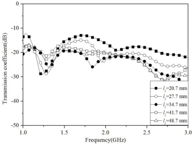
Fig. 7 shows the simulated transmission coefficient characteristics of the proposed antenna for various values of length l2. It can be seen that as the length of l2 increases, the isolation characteristic is improved. However, when l2 is larger than the optimized values of 34.7 mm, the mutual coupling increases in the frequency range from 1.7 GHz to 2.17 GHz. An optimal result is achieved when the length of l2 is set to 34.7 mm.
In order to improve the gain and FBR, substrate 2 with ground 2 is located at 0.28 ╬╗ from the FR-4 substrate 1 that act as a reflector. The length of h is set at about a quarter-wavelength of the center frequency, so that the reflected wave from the reflector is in phase with the forward wave excited by the array antenna [11].
The yz plane radiation patterns for various values of h were simulated and are shown in Fig. 8. The best performance of the peak gain and FBR was obtained when h was 32.4 mm. At 2.16 GHz, the maximum gain and FBR is superior to that of 1.755 GHz and 1.96 GHz, because the optimum distance of 34.7 mm is a quarter-wavelength of 2.16 GHz. As the value of h increases to 44.4 mm, the back lobe becomes larger. The peak gains are 10.14 dBi (FBR = 11.09 dB), 10.58 dBi (FBR = 14.81 dB), and 11.69 dBi (FBR = 27.23 dB) at 1.755 GHz, 1.96 GHz, and 2.16 GHz, respectively.
IV. Measured Results
The comparisons of the peak gains and FBRs between the proposed antenna and the antenna without GND2 are shown in Table 1. The enhancement values of the peak gains and FBR are 5.57 dB (FBR = 10.63 dB), 6.6 dB (FBR = 14.99 dB), and 7.73 dB (FBR = 27.45 dB) at 1.755 GHz, 1.96 GHz, and 2.16 GHz, respectively.
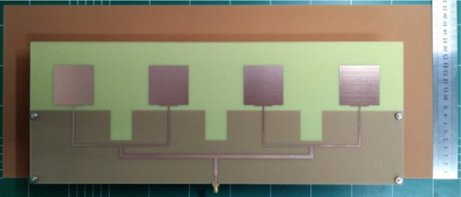
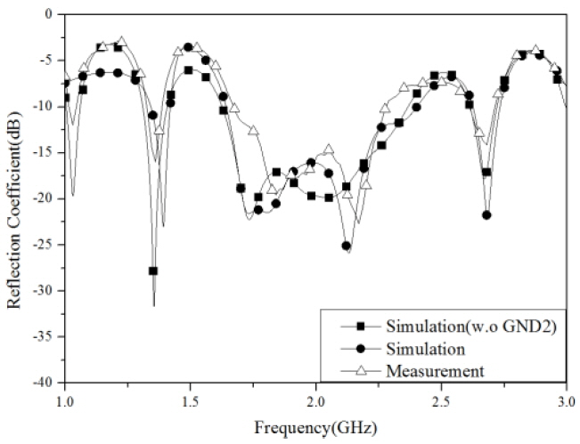
Fig. 9 shows a fabricated prototype of the proposed antenna. The simulated (with and without GND2) and measured reflection coefficients are compared in Fig. 10.
Both the simulated and measured results are in agreement with respect to the reflection coefficients. The measured ŌłÆ10 dB reflection coefficient bandwidth (1.67ŌĆō2.32 GHz) is sufficient to cover GSM-1800, PCS, and UMTS bands.
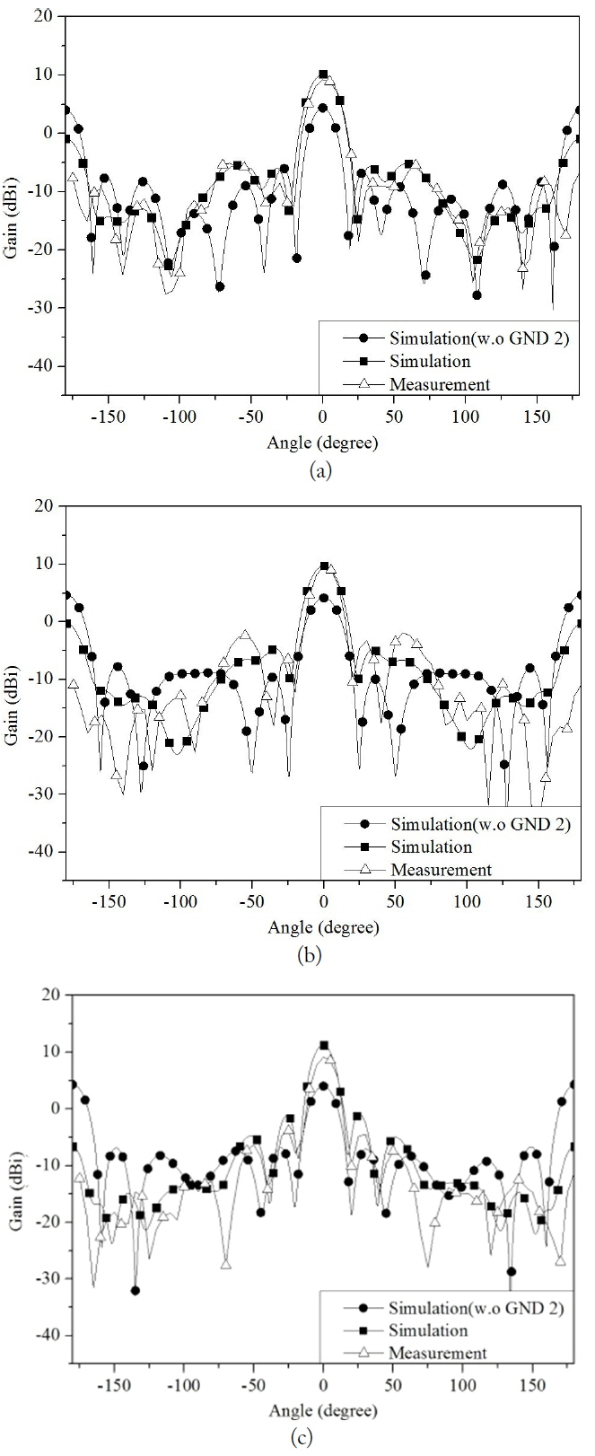
A comparison of the simulated (with and without GND2) and measured 2D radiation patterns of the proposed antenna are shown in Fig. 11. The simulated results are similar to the measurements. At the central frequencies of the operating bands (1.755 GHz, 1.97 GHz, and 2.16 GHz), the measured and simulated radiation pattern are almost identical. The measured peak gains of the proposed antenna are 9.21 dBi, 9.61 dBi, and 9.12 dBi, respectively. The FBRs are 15.83 dB, 20.47 dB and 20.33 dB, respectively.
V. Conclusion
In this paper, a low-profile broadband array antenna for home repeater applications is proposed. By using the coupling feed, the impedance matching of the proposed antenna is improved. Consequently, the proposed antenna has a wide ŌłÆ10 dB reflection coefficient bandwidth of 650 MHz (1.67ŌĆō2.32 GHz) simultaneously covering GSM-1800, PCS and UMTS bands. The addition of slits in the ground plane decreases the mutual coupling with an isolation level lower than ŌłÆ20 dB at the operating frequency band. The antenna has peak gains of 9.21 dBi, 9.61 dBi, and 9.12 dBi with a unidirectional radiation pattern. Therefore, the antenna has the desired properties for repeater applications.