CPW Fed T-Shaped Wearable Antenna for ISM Band, Wi-Fi, WiMAX, WLAN and Fixed Satellite Service Applications
Article information
Abstract
The placement of wearable products integrated with telecommunication systems is having a good impact on healthcare communication all over the world. Embedded communication devices like antennas and RF devices are helping doctors to assess the condition of patients from remote locations. The present work deals with the design and development of a coplanar waveguide fed wearable antenna for ISM band (2.4–2.5 GHz), Wi-Fi, WLAN (2.4–2.48 GHz), WiMAX (3.4–3.6 GHz), and fixed satellite service (3.6–3.7 GHz and 9–11.5 GHz) applications. The designed antenna on jeans substrate (50 × 40 × 1.6 mm) provides a 1.7 GHz bandwidth with a gain of 4.6 dB. A parametric study of different fabrics and the performance characteristics of bending angles are also provided in this work from the application point of view. The simulated results obtained from CST tool and measured results of fabric material based antenna on vector network analyzer are correlated with each other.
I. Introduction
The design of wearable devices opens the doors to mechanisms for monitoring a human being’s health condition. Intelligent wearable devices embedded in textile materials will help considerably with extracting certain parameters of the body to monitor its condition. Medical monitoring is very essential in certain conditions for people who are involved in mining, military, security operations and other risky environments. These people’s health-related data should be transmitted to hospitals and doctors to enable medical assistance in critical situations. Hence, for all these broad applications of data transmission, wearable antennas are an optimal solution [1, 2].
The wireless body area networks associated with wearable antennas should provide solutions for different applications with low transmission power, less complexity, and minimum interference [3–6]. A microstrip patch structure can provide a solution for the design of such wearable antennas in conformal and flexible nature with placement in the clothing [7, 8]. Recently people having been trying to design antennas with textile materials with conductive coating and, in some cases, with 100% pure textiles only [9, 10]. A patient-friendly model can be designed with a washable fabric-based antenna system.
Unlike previous wearable antennas [11, 12], the present antenna design is found to be capable of meeting the requirements of wearable electronic devices, such as being robust, consuming a small amount of power, comfortable to wear with flexible materials. In addition, the current manuscript materials used can guarantee washability of the wearable device and, accordingly, its reuse. The measured results of the present antenna designs are compared with simulations, and good agreement is observed.
II. Antenna Geometry
A T-shaped coplanar waveguide fed antenna is designed on a fabric material-based substrate. The proposed model is presented in Fig. 1; it occupies the dimensions of 50 × 42 × 0.6 mm (Table 1). The antenna is constructed based on the coplanar waveguide structure using the design equations.

Coplanar waveguide fed T-shaped antenna: (a) simulated model and (b) fabricated model.
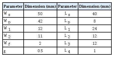
Antenna dimensions
The characteristic impedance can be calculated from
Here k’ and l’ are the complementary modules of K and l. where
W f is the width of the feed line and g is the gap between the feed line and the ground plane.
where h is the height of the substrate and ɛ eff is the effective dielectric constant of the material.
III. Results and Discussion
The designed model is simulated using a CST Microwave Studio and the corresponding results are presented in this section. Fig. 2 shows the reflection coefficient of the antenna with respect to the frequency. The antenna operates at two bands of 2–4 GHz and 9–11.5 GHz with a bandwidth of 2 GHz at fundamental resonant frequency and 1.5 GHz at second resonant frequency, respectively.
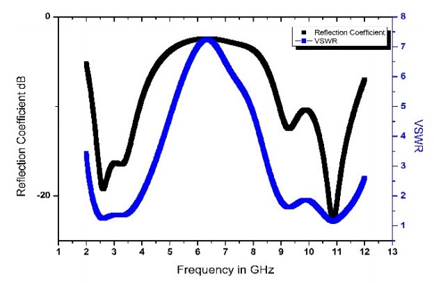
Reflection coefficient vs. frequency.
A parametric analysis of the antenna with respect to its dimensional characteristics was performed. The length of the patch is varies from 6 mm to 8 mm and the corresponding reflection coefficient is presented in Fig. 3. The bandwidth reduced when the length of the patch is decreased from 8 to 6 mm. The dimension of 8 mm for Lp is fixed after optimized results are obtained. The feed width (Wf) is varies from 2 to 3 mm and the corresponding results with the reflection coefficient presented in Fig. 4.
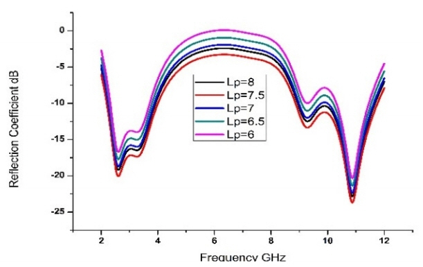
Parametric analysis with change in length of the patch, L p .

Parametric analysis with change in feed width, W f .
Similarly, the width of the patch (Wp) is varies from 36 to 42 mm and is fixed at 42 mm after optimized results were obtained for this dimension (Fig. 5).

Parametric analysis with change in feed width, W p .
The radiation characteristics of the antenna are presented in Fig. 6 for two different frequencies, 2.5 GHz and 3.6 GHz in E-plane and H-plane. In H-plane, an omnidirectional pattern can be observed.
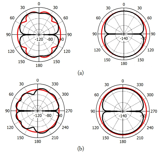
Measured radiation pattern of the antenna: (a) 2.5 GHz and (b) 3.6 GHz.
The simulated surface current distribution of the antenna at three operating frequencies presented in Fig. 7. The current distribution is more at the feed line and on the lower part of the antenna at three resonant frequencies. The upper edges of the ground plane are also showing some significance distribution from the obtained results.
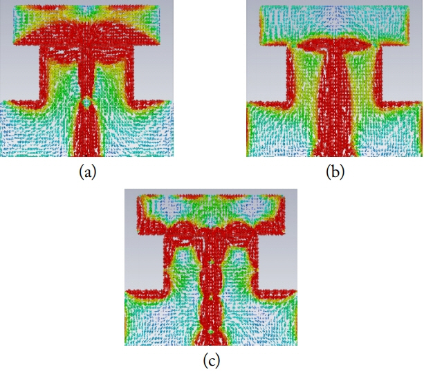
Surface current distribution: (a) 2.5 GHz, (b) 3.6 GHz, and (c) 11 GHz.
A time domain analysis of the antenna is presented in Fig. 8. The input signal and the corresponding impulse response can be observed from the result. A small distortion in the response is due to a mismatch in timing. Fig. 9 shows the testing of the antenna with an Anritsu combinational analyzer.
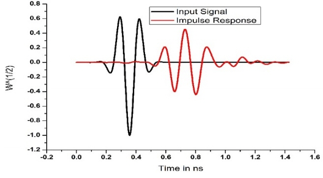
Time domain analysis of the proposed antenna.
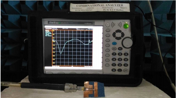
Measurement on Anritsu combinational analyzer.
IV. Study of Other Textile Substrate Materials
This work is extended to encompass a study of the antenna performance characteristics of other textile substrate materials. A list of materials selected for the study is presented in Table 2.

Textile materials parameters
The reflection coefficient and the gain plots for the proposed antenna of different textile materials are analyzed and presented in Figs. 10 and 11, respectively. It can be observed that the antenna impedance bandwidth changes for each fabric from Fig. 10. There is a shift in the operating frequencies of the antenna with respect to the change in the fabric material. A peak realized gain of 4.5 dB is attained for jeans cotton and 4.2 dB for polyester.
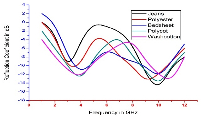
Reflection coefficient vs. frequency for different substrate materials.
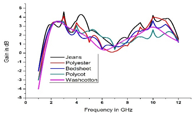
Gain vs. frequency for different substrate materials.
V. Conformal Testing by Placing On Body
After we observed the performance characteristics of the antenna with different fabric materials and we placed the model on the human body. Fig. 12 shows the placement of the antenna on the hand and on the chest and the electric field distribution around and inside at 2.5 GHz. From Fig. 12(b) we can observe that the electric field levels at the back of the body are very low and the radiation efficiency is 65%. Except at the transmitting antenna, many ripples are generated all over the body.

Placement of the antenna and electric field distribution: (a) placement on hand, (b) placement on chest, and (c) electric field distribution.
The conformal behavior of the antenna at different bending angles are presented in Fig. 13. Three bending angles (60º, 90º and 120º) were selected for the experimentation and the performance of the antenna was analyzed. The reflection coefficient of the antenna at different bending angles is presented in Fig. 14.

Conformal testing: (a) 60º, (b) 90º, and (c) 120º.

Performance of the antenna with conformal behavior.
The reflection coefficient of the antenna with different bending angles is presented here. Except for 120º bending, the remaining cases show dual-band operation. For the 120º bend, a notch band occurred at 10 GHz, and in this case, it is behaving like triple-band antenna. Due to low bandwidth, the notching band can be neglected in this case. The performance characteristics are almost the same with respect to the antenna in the planar condition, except for minor bandwidth variation.
The designed antenna is placed on the human hand phantom model as shown in Fig. 15(a) and a radiation analysis of the model is performed at different bending angles of 60º, 90º and 120º. Fig. 15(b)–(d) show the direction of the pattern in a three-dimensional view at the specified bending angles.
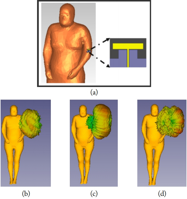
Antenna placement on hand with bending angles: (a) placement on hand, (b) 60º, (c) 90º, and (d) 120º.
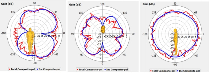
The radiation characteristics of the antenna in the XY, YZ and ZX planes are shown in Figs. 16 –18 at three bending angles. In Fig. 16, at 60º bending placement on the human body, the radiation pattern is like a dipole pattern in the XY plane and quasi-omnidirectional in the XZ plane. At 90º and 120º, the pattern is monopole-like in the XY plane. An omnidirectional pattern in the XZ plane for 90º bending and a quasi-omnidirectional pattern in the XZ plane for 120º can be observed in Figs. 17 and 18.
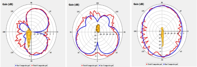
Radiation pattern in XY, YZ, and XZ planes for bending angle of 60º.

Radiation pattern in XY, YZ, and XZ planes for bending angle of 90º.
Radiation pattern in XY, YZ, and XZ planes for bending angle of 120º.
The gain of the antenna when it is placed on the human body is calculated and presented in Fig. 19. The gain variation with respect to the frequency of operation at the three bending angles is similar to each other, except for 0.2 to 0.3 dB variation.
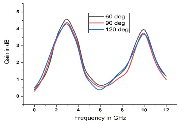
Frequency vs. gain for different bending angles.
VI. Conclusion
A low-profile coplanar waveguide fed antenna is designed for ISM band (2.4–2.5 GHz), Wi-Fi, WLAN (2.4–2.48 GHz), WiMAX (3.4–3.6), fixed satellite service (3.6–3.7 GHz and 9–11.5 GHz) communication applications. The proposed antenna is constructed on textile substrate material of jeans cloth for wearable applications. Other fabric substrate materials like polyester, polycot, bedsheet, and wash cotton are also examined for their applicability, and their performance characteristics are presented in this work. The radiation characteristics and gain parameters with respect to the bending angles on the human body are also presented. According to these results, future antenna designers need to ensure that wearable telecommunication devices operate properly near the human body.
Acknowledgments
Our sincere thanks to the Department of Electronics & Communication Engineering of Koneru Lakshmaiah Education Foundation and DST for their support through ECR/2016/000569 and EEQ/2016/000604.
References
Biography
Mudunuri Padmanabha Raju did his B.E. in Electronics and Communications at S.R.K.R. Engineering College, Bhimavaram from 2004 to 2008. He did his M.Tech. in Communication Systems at Sir C. R. Reddy Engineering College, Eluru. Presently he is pursuing a Ph.D. part-time at K. L. University, Vijayawada and working as an Assistant Professor at Shri Vishnu Engineering College for Women, Bhimavaram.

B. T. P. Madhav received B.Sc., M.Sc., MBA, and M.Tech. degrees from Nagarjuna University, AP, India in 2001, 2003, 2007, and 2009, respectively. He got his Ph.D. in the field of antennas from K. L. University. Currently he is a Professor and Associate Dean at K. L. University. He has published more than 328 papers in international and national journals and conferences. He is a reviewer for several international journals, including IEEE, Elsevier, Springer, Wiley, and Taylor & Francis and has also served as a reviewer for several international conferences. His research interests include antennas, liquid crystal applications, and wireless communications. He is a member of IEEE, a life member of ISTE, IACSIT, IRACST, IAENG, and UACEE, and a fellow of IAEME. He is a member of the editorial boards of 36 journals. He has authored ten books and is guiding eight Ph.D. scholars.

D. S. Phani Kishore is a professor at the Department of ECE of K. L. University. He did his postdoc in Sweden and has published several papers at conferences and in journals. He is a reviewer for several peer-reviewed journals and works in the area of signal processing and communication systems. He is currently guiding four scholars towards their doctoral degrees.