I. Introduction
In the last decade, electromagnetic (EM) simulation has confirmed its presence in the field of the analysis and design of microwave and RF integrated circuits to generate a big library for simulators with a huge number of elements that are geometrically complex and sensible. The study of complex planar circuits seems to be an inexhaustible source of studies and inventions, which have had a significant influence on EM simulation, among other fields [1ŌĆō6].
Today, involved in EM simulation takes larger and complex shapes that can affect the notion of libraries. An introduction of additional restrictions in the elaboration of models and parameters can be a good strategy to account for the topology of the implantations [7, 8]. The complexity related to the number of these parameters tends to reach high levels due to the attitude of ŌĆ£simulate allŌĆØ. In addition, while the data gleaned from experimental measurements are invaluable, the entire process can be costly in terms of money and the manpower required for doing the required machine work, assembly, and measurements in the range. One of the fundamental drives behind reliable computational electromagnetics (CEM) algorithms is the ability to simulate the behavior of devices and systems before they are built.
This led to reformulating and rectifying some CEM methods [9, 10]. Many powerful numerical analysis techniques have been developed in this area in the last decade. As the power of the computer continues to grow, so does the nature of the algorithms applied, as well as the complexity and size of the problems that can be solved. In [11], the authors investigated geometry-aware, high-performance domain decomposition (DD) solvers: These decompose the geometry and create algorithms that fit new mathematics to the geometry. This research enables integrated design and simulation in engineering applications via reconfigurable modeling and reusable simulation: By generating analysis-suitable models per component and independently analyzing individual components, one can hope to automatically assemble components to simulate a virtual prototype of an entire product. This work can overcome some key challenges in high-fidelity design and analysis in microwave engineering, but it remains limited for some complexity problems. In addition, it is no secret that the placement analysis in complex antenna scenarios requires accurate CEM tools. A fundamental requirement to achieve truthful results is that the source antenna must be accurately modeled. However, in many practical cases, a full-wave representation of the physical antenna is unfeasible or unavailable in the format required by the desired CEM solver. For this reason, the work presented in [12] described a procedure to derive, a computationally efficient, full-wave representation of an existing antenna for CEM solvers. The procedure is based on post-processing of the measured antenna pattern. The desired source antenna is measured while situated in a suitable environment, of reduced complexity and size, which locally resembles the final antenna environment. An appropriate selected source in this case can be a good solution for full-wave investigation.
The research presented in [13] examined the fabrication and characterization of radiofrequency (RF) and microwave passive structures on an air substrate using additive manufacturing (three-dimensional [3D] printing). The air substrate was realized by 3D printing RF structures in two separate pieces and snapping them together face to face using a LEGO-like process. Spacers printed on the periphery provided the desired air substrate thickness. Metal patterning on non-planar printed plastic structures was carried out using a damascene-like process. Various RF structures, such as a low-dispersion transmission line, T-line resonator, high-gain patch antenna, slot antenna, and cavity resonator were demonstrated using this process. Despite the performance achieved, the simulation results stayed slow in terms of CPU time. These various limitations can be redressed using the method of moments (MOM) [14, 15] and an advanced transverse wave approach (A-TWA) [16, 17] in the context of the EM-simulation of RF/microwave applications.
In this paper, the strengths and weaknesses of the applied CEM techniques are discussed. The performance in terms accuracy, memory and computational time for specific applications will be evaluated using these numerical methods. This paper is organized as follows: Section II presents the theoretical foundations of MOM and A-TWA, as well as their features and limitations. The proposed planar structures for EM investigation are explained in Section III. The next section evaluates and discusses the different simulation results for EM validation of the proposed structures.
II. Theoretical Background
For most practical interest problems pertaining to EM radiation and scattering, an analytic solution of integral equations formulating the problem cannot be found. Therefore, scientists and researchers frequently adopt a computational techniques axis to obtain a solution. In this section, we briefly present the mathematical background and theoretical foundations of the two well-known numerical EM methods, MOM and ATWA, as well as their main characteristics and strong points.
1. Two-Dimensional MOM
In computational EM, the 2D MOM is a numerical method designed to obtain a numerical solution by transforming integral equations into a linear system.
We start from the general equation in the context of EM applications:
where L is an integro-differential operator, f is the unknown function, and g is a known excitation source.
Obviously, f can be expanded into a sum of N *M weighted basis functions, as follows:
Due to the linearity of L, (1) can be expressed as
where (╬▒mn)mn denote the unknown weighting coefficients.
A judicious choice of basis functions is highly important for modeling the expected behavior of the unknown function throughout its domain. The basis functions can be either sub-sectional or global, according to whether they relate to local or entire-domain problems.
By applying the inner product between testing basis functions fpq and (3), the entire problem can be reduced to
Relation (4) can be written as the well-known matrix equation:
where
Referring to the system depicted in (5), it is clear that the computational complexity effort presented in 2D-MOM is important, since all matrix elements Zmn, pq should be computed and then explicitly stored in memory. To accelerate the solution of the MOM linear system, Heldring et al. [18] proposed a sparsified adaptive cross approximation (S-ACA) algorithm by substituting sub-blocks of the impedance matrix Z using ŌĆ£compressedŌĆØ approximations, which allowed for reduced storage and accelerated iterative solution. The obtained numerical experiment reveals a computational complexity close to N log N.
As mentioned above, to obtain a good solution for the problem, the choice of the testing function is decisive; this is mainly the case for the EM applications with high complexity problems. The Galerkin method was introduced to overcome this difficulty, since the basis functions are used as the testing functions. This has the benefit of imposing the boundary conditions in the solution domain, in place of using discrete points, which is done in the point-matching technique [19, Section 3.7, pp. 58ŌĆō60]. The Galerkin method is considered an efficient mathematical tool to solve many problems in several domains; this was presented in the approach developed by our research team in [20].
2. Two-Dimensional Transverse Wave Approach
The 2D transverse wave approach (TWA) approachŌĆöa fast numerical method based on the iterative process and developed by our research teamŌĆöis a subject of many recent publications [21, 22]. It has several potentialities that set it apart from other computational EM approaches. Indeed, there are no matrix inversion calculations in the TWA process, no constraints are required on the component forms, no numerical instabilities frequently arising from large matrices can be found, and the convergence is guaranteed independently of the interfaces of the studied planar structures. Below, we present a rapid theoretical background of TWA method.
Starting by combining the solutions of the MaxwellŌĆÖs equations and the translational invariance of the waveguide geometry in the z-direction, the field intensities E and H can be expressed as:
where
and the superscript T refers to the tangential components.
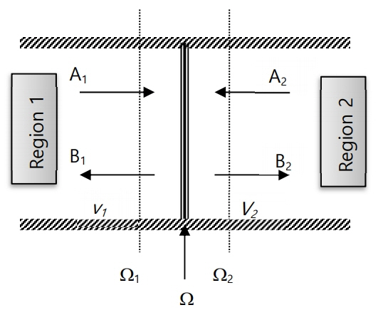
The wave concept is introduced to ensure the conversion from integral formulations of the EM field to algebraic problems. Therefore, the linear combination between the transverse electric field (ET) and transverse magnetic field (HT)generates both incident and reflected waves from the discontinuity interface (see Fig. 1).
The following general equation represents the key of our TWA approach:
where Z0i stands for the wave impedance of the homogeneous isotropic region iŌłł{1,2} (Fig. 1), which is given by:
Here, ╬Ę0 is the intrinsic impedance of free space defined as
╔øri,╬╝ri, are the relative permittivity (capacitivity) and relative permeability (inductivity) of the medium i; JT = HT├Śv, with v denoting the outgoing normal vector oriented towards region i; and Žä is a Boolean parameter referring to the wave nature (i.e., Žä = 0 for incident wave ([W = A] and Žä = 1 for reflected wave [W = B]).
Based on wave concept, the EM problem can be reduced to the following iterative scheme, avoiding any operator inversion process:
where
B0 is wave excitation source;
(n) is the iteration order and the underlined waves are presented in the spatial domain, the others in the modal domain;
╬ō╠é and ┼£ are two linear operators in Hilbert space;
╬ō╠é denotes the reflection operator in the modal domain; and
┼£ defines the diffraction operator in the spatial domain, describing the boundary conditions from the discontinuity surface ╬®.
Let ╬öW(n) be the difference in terms of waves between two successive waves, W(n) and W(nŌłÆ1), as follows:
The system depicted in (14) can be rewritten in the following form:
Taking into account the losses, the spectral radius of ┼£ that is less than unity, and the unitarity of ╬ō╠é demonstrates that the spectral radii of ||╬ō╠é┼£|| and ||┼£╬ō╠é||are less than unity. Consequently, the norms||╬öB(n)|| ŌåÆ 0 and ||╬öA(n)|| ŌåÆ 0 and the convergence of (16) is reached. This proves the stability of our TWA approach.
The detailed mathematical development of this method can be found in our work presented in [17].
The transformation between the modal and spatial domains is guaranteed by the 2D fast Fourier transform. Like MOM in its accelerated version, the presence of the sparsity problem, mainly in the analyzed structures with very high resolution, offers the possibility to accelerate TWA by introducing the 2D non-uniform fast Fourier mode transform that was already successfully developed by our research team in [23]. The time complexity effort of TWA is around N log N where N represents the total number of pixels chosen for the EM simulation of the studied structure.
Table 1 highlights the difference between our TWA approach and the MOM method in terms of the storage requirements, CPU computation time, meshing and pre-processing in the context of RF and microwave integrated circuit design.
III. Proposed Structures for EM Investigation
This section sheds light on two different planar structures already presented and studied in [24] using ultra-thin flexible substrates. These antennas undergo full-wave investigations in the context of complex RF and microwave applications using both the advanced MOM and TWA methods.
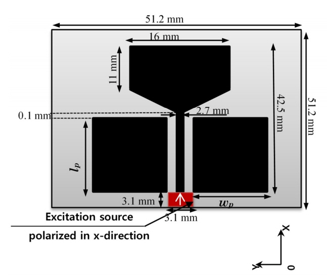
1. First Planar Structure: Printed Trapezoidal Monopole Antenna
The antenna depicted below (Fig. 2) is geometrically symmetrical and composed of a trapezoidal radiating patch and coplanar feeding line.
To conduct these two parts, copper is introduced. This antenna has many features that where presented in [24]. It is considered a judicious choice since it offers the possibility, in the context of RF/microwave circuit simulations, of defining a planar excitation source that will be considered as bilateral polarized in the x-direction.
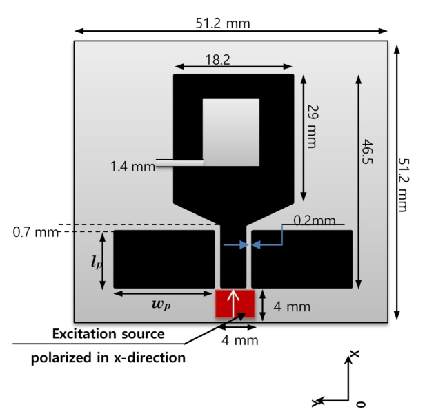
2. Second Planar Structure: A Strip-Loaded Coplanar Waveguide Fed Pentagonal Antenna
The second planar structure shown in Fig. 3 is geometrically asymmetrical and consists of a strip-loaded coplanar waveguide (CPW)-fed pentagonal antenna, already described in [24]. This kind of antenna is highly useful in the context of GPS/WiMAX/WLAN applications [6]. Like the previous antenna, it will be excited by a bilateral planar source polarized in the x-direction.
IV. Simulation Results and Discussion
The proposed planar structuresŌĆÖ antennas are simulated using the two numerical EM approaches, MOM and TWA, and compared with the obtained results in [24]. In the study [24], three state-of-the-art simulation tools were used to analyze the scattering parameter S11, and the results were then compared against accurate measurements obtained inside an anechoic chamber. These methods are the finite integration technique (FIT)-based time domain solver (TDS), finite element method (FEM)-based frequency domain solver (FDS) of CST microwave technology, and the FEM-based High-Frequency Structure Simulator (HFSS) of ANSYS. For our simulation results, the well-known state-of-the-art simulation tool, the so-called Advanced Design System (ADS) Momentum, and our EM simulation tool, well-developed in [25], were used for the EM investigation. These tools were developed based on the MOM and TWA methods, respectively. Table 2 displays the different geometric and modeling simulation parameters for EM analysis of the aforementioned planar antennas presented in Figs. 2 and 3. These parameters have been chosen judiciously to be much closer to the one chosen in [24].
We have noted that, in [24], a hexahedral mesh was applied in the TDS, and the tetrahedral mesh in the FDS and HFSS were mainly used for the substrate and feeding width/gaps; a total of 37,104,270 cells was used, for example, to provide enough representation of the trapezoidal antenna geometry. Moreover, we adopted a uniform and isotropic mesh in our simulations based on the TWA approach, with a total of 262,144 cells. This represents only 0.7% of the resolution used in [24], and a huge difference can be observed in terms of the total number of cells that can affect at tremendous rate on the time complexity effort between numerical methods.
Moreover, there is no doubt that the substrate should be in light of the initial design of the studied antennas, relative to the feeding structure; in fact, the effect of the substrate resistivity can be observed principally on the even modesŌĆÖ attenuation and/or reduction apart from the slow-wave range, as described in [26].
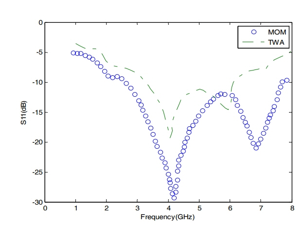
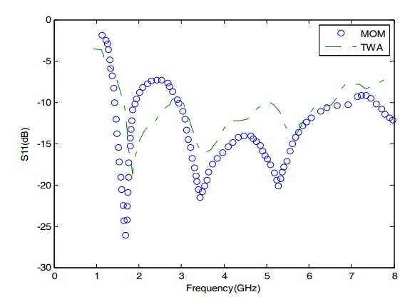
The analysis of the scattering parameter, S11, of the two reference antennas underlines the EM validity in the context of EM-modeling of complex RF/microwave structures referring to the specific data mentioned above. Indeed, on the one hand, the simulation results for the trapezoidal antenna depicted in Fig. 4 show two bands using MOM and TWA. The first MOM band appears from 2.79 GHz to 4.88 GHz, while the TWA band appears from 3.26 GHz to 4.73 GHz; the second band is detected from 5.84 GHz to7.43 GHz for MOM and from 5.65 GHz to 6.12 GHz using TWA. On the other hand, for the strip-loaded CPW-fed pentagonal antenna, the results prove the presence of the different resonant bands with small shifting. These obtained simulation results, based either on the MOM or TWA method and as depicted in Figs. 4 and 5, respectively, are nearly identical to the results in [24]. The satisfactory agreement of these results demonstrates the potentialities of these approaches; nevertheless, TWA remains more flexible and efficient than MOM owing to the minimum complexity effort pertaining to the fast iterative process of TWA. The fluctuations observed in Fig. 5 are due to the presence of the periodic walls, which can be circumvented by setting the antenna as far as possible from the walls. This can be performed by increasing the input resolution, which can adversely affect the total CPU time for EM simulation. In this case, the anisotropic mesh technique (AMT) developed by our research team and already implemented in the advanced TWA approach can be a good solution for tackling this problem.
V. Conclusion
In this paper, the two numerical EM methods of MOM and TWA, with their advanced versions, were presented in the context of complex RF/microwave applications. The benefits and limitations of these methods were exposed. Moreover, two different complex planar antennas were successfully presented, tested, and implemented using different solvers. The impact of the substrate resistivity on the EM simulation has been shown. A comparative study of our obtained simulations results with the literature proved the potentialities of these methods in terms of their simplicity and time complexity effort. The AMT technique can improve the TWA process to investigate planar structures at a high resolution, particularly those used in 5G technology.