Design and Investigation of a Miniaturized Single-Layer ACS-Fed Dual Band Antenna for LTE and 5G Applications
Article information
Abstract
Presently, a single compact antenna is expected to operate in multiple frequency bands, so that it may be used for multiple applications. In this regard, a compact asymmetric coplanar strip (ACS) fed monopole antenna was designed to operate in LTE band-40 and 5G mid band frequencies. To achieve the desired dual band frequency, meander line radiating structure was used. The uniplanar design with the ACS feed considerably reduced the antenna size to 19.25 × 10.5 × 1.6 mm3. This miniaturized dual band antenna can be easily integrated into circuit boards. The measured and simulated results provided a reflection coefficient (S11) < −15 dB, which made the antenna suitable for LTE band-40 and 5G mid-band communication applications.
I. Introduction
Today, a single communicating device is expected to be capable of operating in multiple frequency bands based on applications such as WLAN, GPS, Bluetooth, WiMax, cellular mobile communication, and so on. To achieve compactness in the design of all components and circuits, considerable research has been conducted and is ongoing [1]. Furthermore, from an antenna design perspective, a single antenna with compact size has to operate in multiple frequency bands, which remains a challenging task. In the literature, to achieve a compact multiband functionality antenna, different radiating and ground plane structures and feeding techniques have been proposed. The various feeding techniques considered in antenna designs include microstrip feed, coplanar waveguide (CPW) feed, coaxial feed or asymmetric coplanar strip (ACS) feed [2]. To integrate the antenna with the radio frequency circuitry, uniplanar antenna design is well suitable (i.e., having the radiating patch and ground plane in a single layer) [1]. To feed the uniplanar design antenna either the CPW feed or ACS-feeding technique is used [3–8].
Different structures, such as L-shape, inverted L-shape, F-shape, mouse-shape, meander line, circular slot, U-shape slot, etcetera, are considered in the radiating patch and ground plane to achieve multiband functionalities in an antenna [4–6]. The ACS-fed meander line radiating structure is used to obtain antenna operation in WLAN and WiMax applications [4]. To operate in triple operating frequency bands, a mouse-shaped radiating strip has been proposed in [7]. Anil Kumar et al. [8] reported an F-shaped radiating patch that allows the antenna to operate in three bands such as digital cellular system (DCS), Wi-Fi and WiMax applications. Metamaterial-inspired conformed antenna design has been implemented to obtain dual band operation at Wi-Fi and WiMax frequencies [9]. Four pairs of circular and square slots are cut from the radiating patch to obtain dual band operation in WLAN bands [10]. An L-shaped microstrip line was used to obtain dual band operation in [11].A slit-loaded semi-circular ring radiating patch with asymmetric microstrip feeding allows the antenna to operate in triple bands such as WLAN, International Telecommunication Union (ITU), and X-band application [12]. An F-shaped ACS-fed monopole antenna operating in GPS, Wi-Fi and WiMax frequency bands was proposed in [13]. In the literature, a modified split ring resonator (SRR) structure is designed on an optically transparent substrate to obtain the WLAN dual band operation [14]. A D-shape SRR configuration is used in the antenna design to work in the WiMax and C-band applications [15]. Further compact and single-layer multi-band antennae operating at different mobile communication bands are needed based on an analysis of the available literature.
In this paper, a meander line structure ACS-fed dual band monopole antenna is proposed for operation within mobile communication Long Term Evolution (LTE) band-40 (2.3–2.4 GHz) and 5G mid-band (3.4–3.8 GHz). The following sections provide a detailed description of the antenna design evolution process, the parametric study that was conducted, the fabricated antenna, and a discussion of the results.
II. Antenna Design Evolution Process
The proposed meander line antenna structure was designed in a single side copper-platted FR4 substrate with 1.6 mm thickness. The proposed antenna’s basic structure was derived from the literature [4]. The authors designed an antenna to operate in WLAN dual band, that is, 2.4 to 5 GHz. In the proposed design, different sizes of radiating strips are inserted to operate in LTE band-40 and 5G mid frequency bands used in mobile communication applications. In order to design an electrically small antenna, the electrical length of the antenna “βa” should be less than one [16]. Here “β” represents the free space wave number, and “a” is the radius of the imaginary sphere that encloses the antenna. 0.841 < 1 at the maximum operating frequency 3.6 GHz. The steps of the proposed antenna development are depicted in Fig. 1.
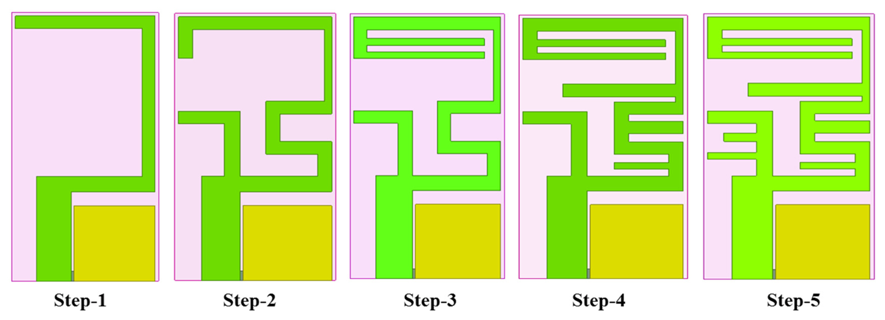
Proposed antenna design evolution process.
The following are the steps considered for the proposed antenna design:
Step 1: An inverted rectangular C-shape strip is supplied with ACS feeding. The resulting operating frequency is between 3.12 and 3.28 GHz.
Step 2: By making rectangular bends in the inverted C-shape, the total length of the radiating element is increased and a new inverted L-shape radiating strip is attached to the feed line. The operating frequency is changed to 2.65 to 2.71 GHz as the length increases.
Step 3: Two rectangular radiating strips of 0.5 mm length are added at the end of the rectangular bend. This helps to achieve the 2.3–2.34 GHz operating frequency, which is within the LTE band-40 frequency.
Step 4: To obtain dual band operating frequency, three rectangular radiating strips are included in the middle of the rectangular bend. It allows the antenna to operate in dual band frequencies: 2.36–2.4 GHz and 3.4–3.46 GHz.
Step 5: Two radiating strips are added in the inverted L-shape to adjust the operating frequency within the 5G mid frequency band. The obtained frequency of operation in the final design is 2.36–2.4 GHz and 3.44–3.5 GHz.
The reflection coefficients obtained at various steps are illustrated in Fig. 2.
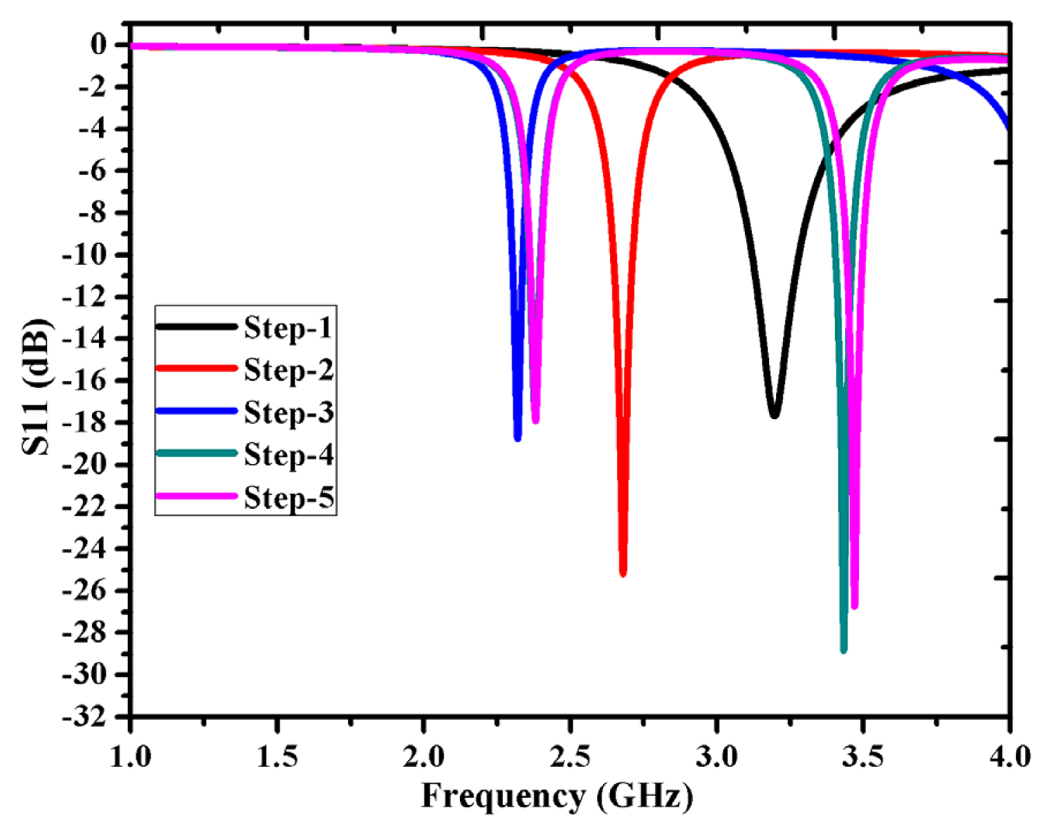
Reflection coefficient obtained in the antenna design evolution process.
The proposed dual band antenna’s geometry representation is depicted in Fig. 3. The total dimension of the antenna is L × W mm2. The ground metallic surface occupies an area of Lg × Wg mm2. The gap introduced between the ground and radiating metallic surface near the feed point is 0.2 mm. The dimension of the rectangular strips added in the radiating surface is demonstrated in Table 1.

Geometry of the proposed design.

Parameters of the designed compact meander antenna
Using the antenna design concept, the height of the antenna (h) is directly proportional to its wavelength [17]. Here, a printed meander line (rectangular strip) design is considered. To radiate the antenna at 2.35 GHz, the monopole antenna should have a length of 31.91 mm. To have the radiation at 3.5 GHz, 21.43 mm is the required antenna length. Four E-shape meander line structures are used in the design and are shown in Fig. 4.
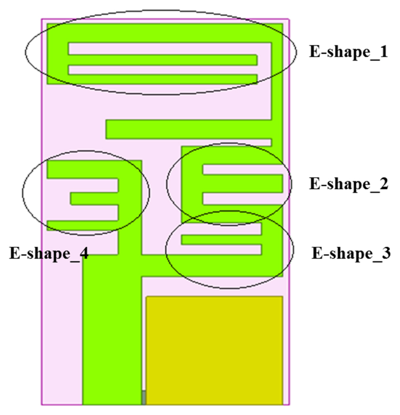
E-shape structures in the proposed design.
In the design, E-shape_1 from the feed line plays a major role in tuning the antenna at a resonant frequency of 2.35 GHz. Furthermore, E-shape_3 helps the antenna tune to the resonant frequency at 3.5 GHz. Fig. 5 depicts the equivalent circuit of an E-shape. The strip line is represented as an inductor, and the gap between two strip lines are modelled as a capacitor. As the width or length of the strip line varies, the resonant frequency varies. The resonant frequency is given by:
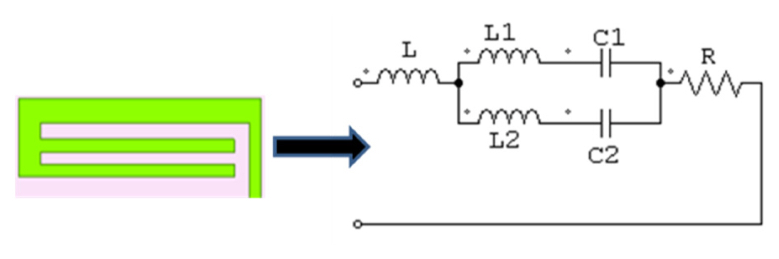
E-shape equivalent circuit.
where Ceq and Leq represent the capacitor equivalent value and inductor equivalent value, respectively. The variation in resonant frequency occurs as the length and width of the strips differ and is discussed in the next section.
III. Parametric Study
The length and width of the rectangular strips were varied using parametric analysis and an optimum value was obtained. Fig. 6 displays the variation of the reflection coefficient (S11) when the ground length (Lg) changes. As the ground length increases, the reflection coefficient of the LTE band-40 decreases, and when Lg decreases, the operating frequency moves away from the LTE band. Similarly, the operating frequency shifts away from the 5G mid-band as the Lg value increases or decreases from the optimal value. Based on the parametric study on ground length, the optimal value considered was Lg = 5.4 mm.
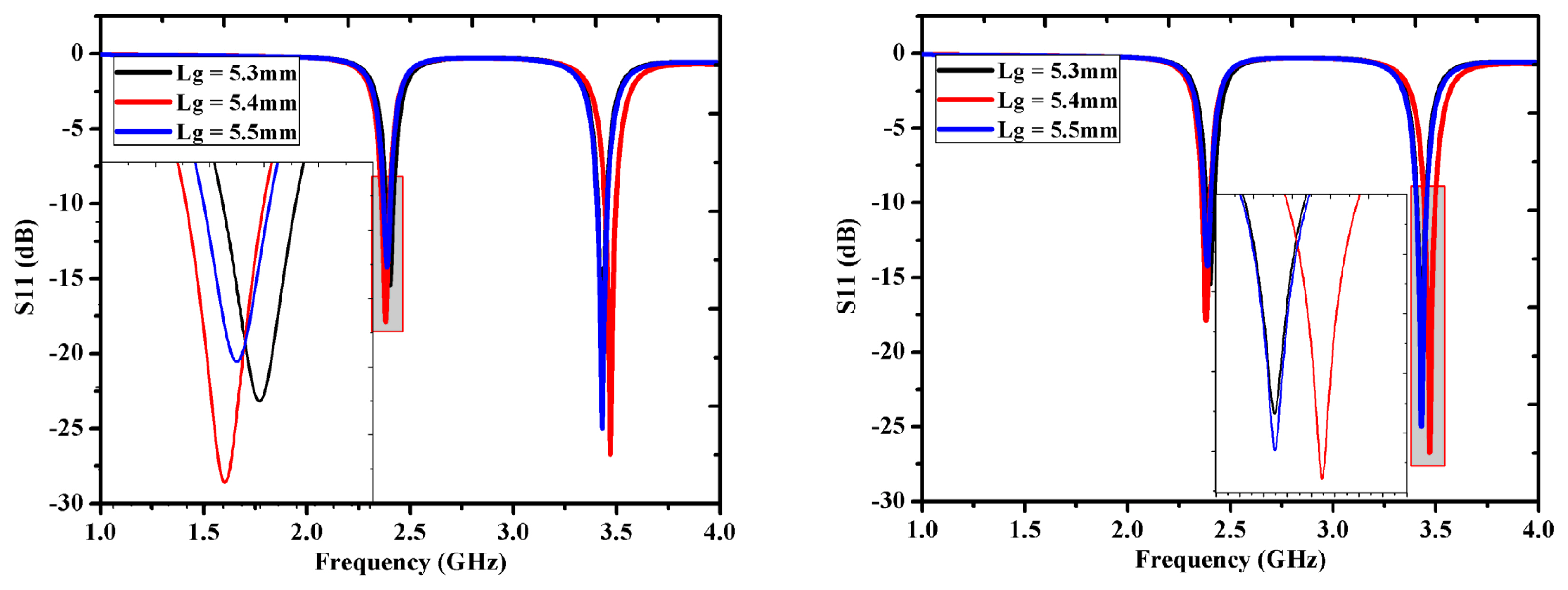
Influence of ground length (Lg) variation on S11.
The parametric study was conducted on the rectangular strips inserted in the proposed antenna design. The strip length and width were determined using the parametric analysis. Fig. 7 illustrates the variation in reflection coefficient and the operating frequency as the length (L1) and width (Ws) of the rectangular strip vary. As the rectangular strip width (Ws) decreases from the optimal value, the highest operating frequency shifts away from the 5G mid-band. Increase in Ws, shifts the 5G frequency band below the operating frequency. Similarly, the variation in L1 alters the desired frequency of operation and the reflection coefficient, as depicted in Fig. 7(b). The optimal value considered for Ws and L1 are 0.5 mm and 1.1 mm, respectively.
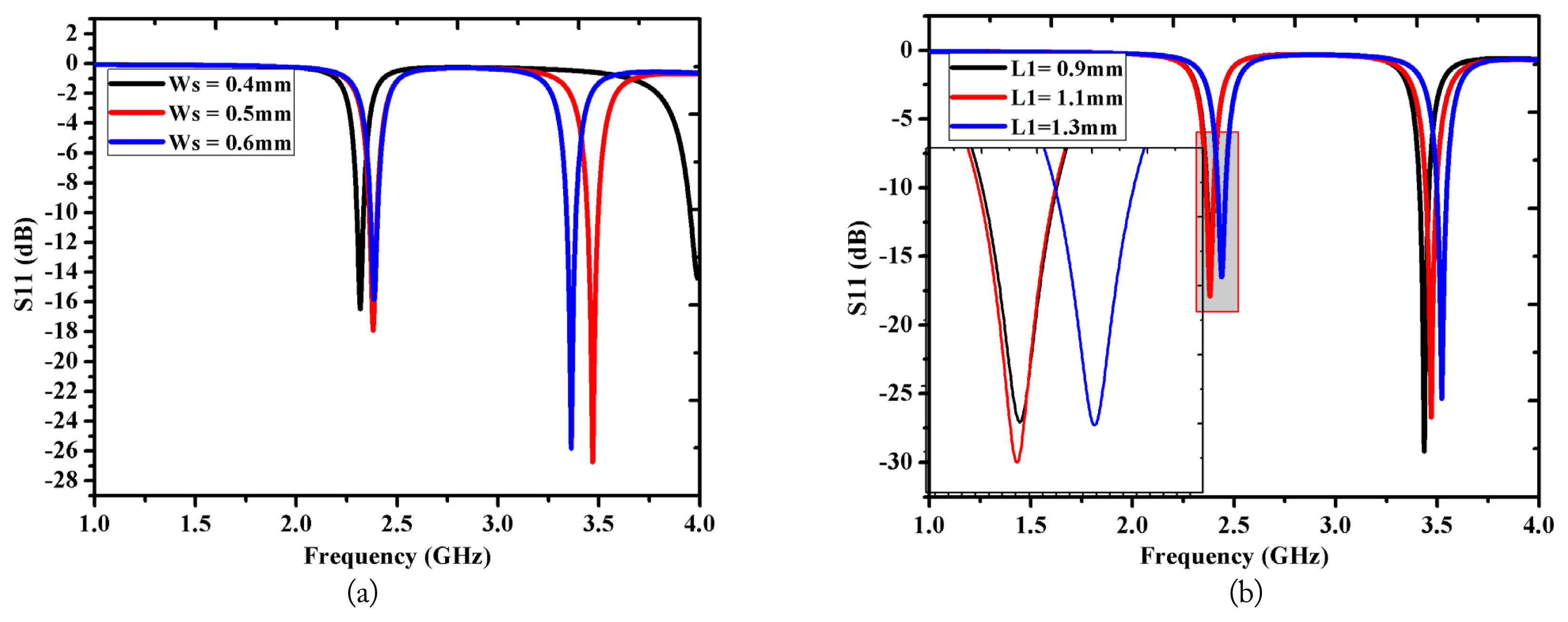
Influence on S11 by variation of the rectangular strip: (a) width (Ws) and (b) length (L1).
The surface current distribution at 2.35 and 3.5 GHz are shown in Fig. 8. At 2.35 GHz, the current distribution is near the end of the horizontal and vertical radiating rectangular strips. The current path length is equal to 32.4 mm. This path length is very close to λg/4 (monopole antenna length), contributing resonance at 2.35 GHz. At 3.5 GHz, the current distribution is close to the feedline, and the current path length is approximately 22 mm.
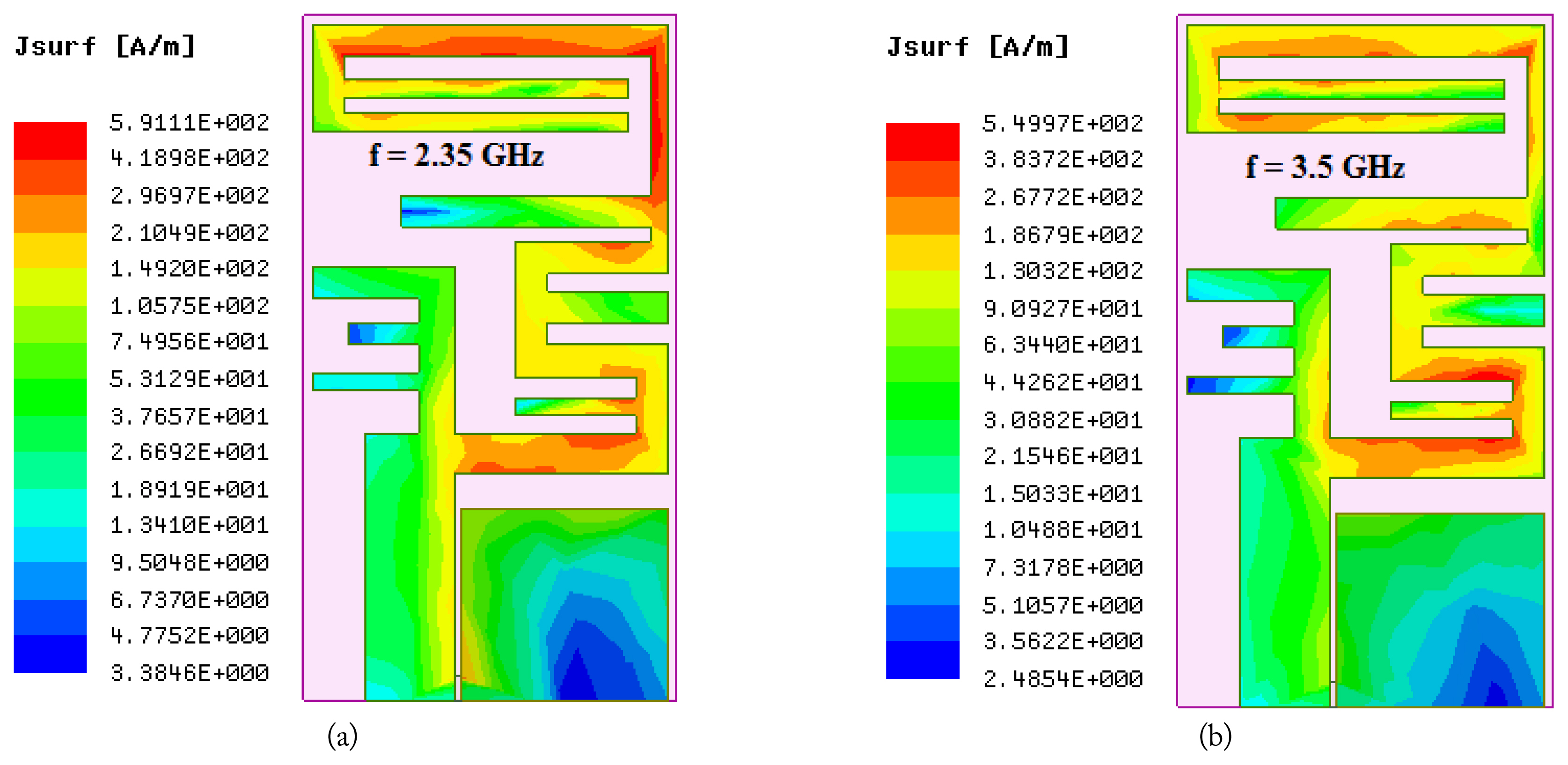
Current distribution at (a) 2.35 GHz and (b) 3.5 GHz.
Radiation pattern provides information about the distribution of the radiating energy from the antenna to other devices. Fig. 9 depicts the simulated radiation pattern at frequencies of 2.35 and 3.5 GHz when angle Phi (φ) is zero degree. At φ = 0°, the radiation pattern considered is in the XY-plane. The obtained “8” shape radiation pattern reveals the omnidirectional radiation behaviour.

Radiation pattern for φ = 0º at (a) 2.35 GHz and (b) 3.5 GHz.
IV. Fabricated Antenna and Results
The simulated antenna using High Frequency Structure Simulator (HFSS) software was fabricated in single-side copper plated FR4 substrate with a relative permittivity of 4.4 and is depicted in Fig. 10. The overall dimension of the fabricated antenna was 0.13λ × 0.083λ × 0.0125λ mm3, where “λ” is the lowest resonant frequency (2.35 GHz) of the operating band. The reflection coefficient and voltage standing wave ratio (VSWR) of the fabricated antenna was measured using an N9915A network analyser, which is shown in Fig. 8. The fabricated antenna provided dual band operation with a good reflection coefficient, ≤ −15 dB.
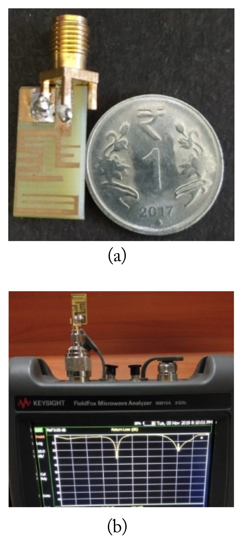
(a) Fabricated antenna and (b) Measurement setup.
Reflection coefficient (S11) is the parameter that indicates the impedance mismatch level in the antenna design. This in turn provides the evidence of VSWR. In terms of S11, VSWR is given by (1 + S11)/(1 − S11). The simulated and measured reflection coefficient is shown in Fig. 11(a). The minimum reflection coefficient was −17.904 and −26.5 dB for 2.36–2.4 GHz (LTE band-40) and 3.44–3.5 GHz (5G mid-band) frequency bands, respectively.

(a) Antenna reflection coefficient characteristics and (b) VSWR characteristics.
The measured minimum S11 value was −32.433 and −22.92 dB for the frequency bands of 2.23–2.35 GHz (LTE band-40) and 3.3–3.6 GHz (5G mid-band), respectively. The fabricated antenna operated in a wide band due to the soldering of an SMA connector or due to fabrication tolerance. The measured VSWR ranged between one and two for the operating frequency band and is depicted in Fig. 11(b).
The peak gain obtained for the simulated antenna was 1.05 dBi and 0.63 dBi for the LTE band-40 and 5G mid-band, respectively. Radiation efficiency is defined as the ratio of the power radiated to the amount of power accepted by the antenna at its input. Radiation efficiency (η) is based on the gain (G) and directivity (D) of the antenna and is given by η = G/D. The corresponding radiation efficiencies of the designed antenna for LTE band-40 and 5G mid band was 70% and 34.91%, respectively. The truncated ground and the insertion of small rectangular strips provided the desired operating frequency with comprise in the radiation efficiency in 5G mid-band. Table 2 shows the comparison of the proposed antenna with the existing designs in the literature. With compact size and ACS feed, the proposed antenna could operate in dual band, with a gain greater than 0.5 dBi.

Comparison of the proposed antenna size with state-of-the-art studies
V. Conclusion
Using simple rectangular radiating strips, a dual band operating antenna was proposed. The designed antenna could operate in LTE band-40 and 5G mid-band mobile communication applications. The use of particular length and width for a rectangular strip in the proposed design was discussed in detail. In terms of size, the proposed antenna geometry (19.25 × 10.5 × 1.6 mm3) is compact and is designed in a low cost FR4 substrate. The designed antenna was fabricated and verified experimentally. The achieved frequency of operation was 2.23–2.35 GHz (LTE band-40) and 3.3–3.6 GHz (5G mid-band).
References
Biography

Shine Let Gunamony
received her M.E. degree in Communication Systems from the SSN College of Engineering, Anna University, India in 2007. Her research interests are in wireless networks, multi-band antenna design, reconfigurable antenna design, and optimization techniques.

Josemin Bala Gnanadhas
received her bachelor’s degree from Bharathidasan University, Tiruchirappalli, in 1996, and her master’s degree from REC, Trichy in 1999. She was honored with a Ph.D. from Anna University, Tamilnadu in 2008. Currently she is working in the Department of Electrical and Computer Engineering, Karunya Institute of Technology and Sciences, Coimbatore as a professor. She is interested in research on RF systems and Communication Networks. Her works have been published in a number of proceedings and indexed journals. Recently, she was awarded for her excellence as a woman educator by NFED in 2017 for her contributions and achievements in the field of engineering. She is an IEEE Senior Member, an associate member of the Institution of Engineers (India) and a life member of ISTE.

Diana Evangeline Lawrence
received her B.E. degree in Electronics and Communication Engineering from Saranathan College of Engineering, Tiruchirapalli, India in 2018. She completed M.Tech. degree in Communication Systems at Karunya Institute of Technology and Sciences, Coimbatore, India in 2020. Her research interests include multiband antenna design and reconfigurable antenna design.