Improved Discrete-Time Boundary Condition for the Thin-Wire FDTD Analysis of Lossy Insulated Cylindrical Antennas Located in Lossy Media
Article information
Abstract
For the thin-wire (TW) finite-difference time-domain (FDTD) analysis of lossy insulated antennas surrounded by lossy media, an improved discrete-time boundary condition (DTBC) at the interface is proposed here. In previous TW-FDTD techniques, the DTBC formulations on the material discontinuity between the lossy insulation and lossy surrounding media were derived from the dielectric constitutive relation under the uniform field approximation (UFA) over each time step. In this paper, to achieve higher accuracy, an improved DTBC is formulated from Maxwell’s equations under the linear field approximation (LFA) and subsequently corrected in the TW-FDTD update equation. By comparing the input impedances of Teflon-insulated cylindrical monopole antennas located in wet soils, we show that the proposed approach provides higher accuracy than previous techniques.
I. Introduction
In telecommunications, geophysical explorations, and diagnostics, insulated cylindrical antennas have often been located in lossy media such as soil, water, or biological tissue [1]. The electromagnetic characteristics of antennas and wave propagation in inhomogeneous media have been analyzed using the finite-difference time-domain (FDTD) method [1–4]. However, since the standard FDTD is based on the time and space discretization of Maxwell’s equations, the fine geometries of the antennas should be modeled as fine grids with sufficiently small cell sizes relative to the minimum wavelength. This results in low computational efficiency due to the large number of cells. One the other hand, thin-wire FDTD (TW-FDTD) treats a coarse grid with the pre-correction of near-field behavior around thin electrically insulated antennas [3, 4]. Therefore, TW-FDTD can provide sufficient accuracy, equivalent to finegrid FDTD, while maintaining higher computational efficiency. In [3, 4], the loading effect of both the insulation and surrounding media was considered by using discrete-time boundary condition (DTBC) formulations. These were derived from the dielectric constitutive relation on the material interface between the lossy media under the uniform field approximation (UFA) over each time step. However, the electromagnetic fields on the material interface are fast varying, and the standard FDTD method is based on the linear field approximation (LFA) in time and space. Therefore, the LFA over each time interval may be suitable for the DTBC formulation. In this paper, we propose an improved DTBC by using a discrete-time version of Maxwell’s equations under the LFA. The DTBC is corrected in the TW-FDTD update equation. By comparing the input impedances of Teflon-insulated cylindrical monopole antennas located in wet soil, we show that this approach is more accurate than previous techniques.
II. Improved DTBC Formulation for TW-FDTD
Fig. 1 shows a FDTD unit cell for the TW modeling of a lossy insulated cylinder in a lossy surrounding medium. A conductive cylinder of outer radius a lies along the z-axis and is insulated with a lossy dielectric material of outer radius ρi, permittivity ɛi, and conductivity σi. The insulated cylinder is surrounded by a lossy dielectric medium of permittivity ɛs and conductivity σs. Since the geometry of the cylinder is rotationally symmetric along the φ-direction, we use the two-dimensional (2D) cylindrical FDTD of the discrete space (ρz) = (iΔρ, jΔz) ≡ (i,j) and discrete time t = nΔt ≡ n [4]. Here, Δρ and Δz are the spatial steps along the ρ and z axes, respectively, and Δt is the time step. The variables (i,j) and n are the integer indices of the space and time discretization, respectively.
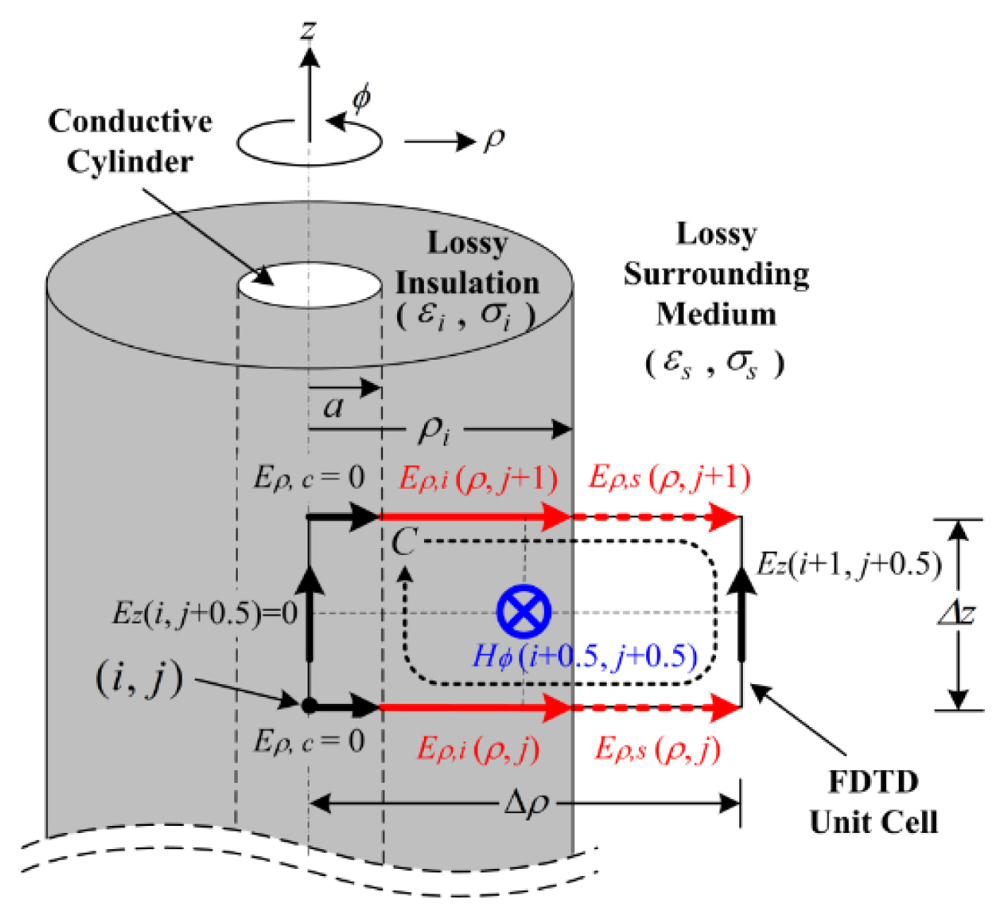
TW-FDTD modeling of a lossy insulated cylinder surrounded by a lossy medium.
The LFA over each time step can be represented as the central-difference and the time-averaging schemes in the differential form of Ampere-Maxwell’s law at t = (n − 0.5)Δt as
In Fig. 1, the tangential electric and magnetic fields on the material interface (ρ = ρi) between the insulating and the surrounding media should be continuous:
where the subscripts i and s denote the insulating and surrounding media, respectively. Applying (2) and (3) to (1), an improved DTBC for the discontinuity of the normal electric fields on the interface can be obtained:
From (4), the normal electric field at t = nΔt in the surrounding medium on the interface can be given as
In (5), the first term on the right-hand side is the DTBC of the present time t = nΔt, and the second term is the DTBC that includes the convolution effects of past times t = (n − 1) Δt,…, Δt, and 0. Table 1 shows a comparison of the DTBC coefficients used in previous versions of the technique and the proposed TW-FDTD framework. All TW-FDTD equations, except for those for the DTBC coefficients, are the same as those in [4]. Therefore, they were omitted here for brevity.

Comparison of the DTBC coefficients in different TW-FDTD formulations for lossy insulated cylinders in lossy surrounding media
III. Comparison Results
To evaluate the computational accuracy of the proposed TW-FDTD technique using the improved DTBC formulation, we calculate the input impedances (Zin = Rin+jXin) of Teflon-insulated cylindrical monopole antennas in wet soils. The conductive cylinder of an antenna has a = 0.635 mm, an axial length of 100a, and ρi = 1.614a and is insulated with Teflon (ɛi = 2.1ɛ0, σi = 5.0 μS/m [4]). The insulated antennas are surrounded by 5%–25% wet soil and are fed by a 50 Ω coaxial line. In all FDTD simulations, the spatial steps along the radial and axial directions are Δρ = 3.23a and Δz = a, respectively. Under the stability condition, we use a time step of Δt = min(Δρ, Δz)/2v, where v is the wave velocity in the medium. First, in the case of the Teflon-insulated monopole antenna inserted in 15% wet soil (ɛs = 5.3ɛ0 and σs = 0.117 S/m [5]), the results of our approach are compared with those of previous TW-FDTD formulations [3, 4] and with fine-grid finite-element method (FEM) data, as shown in Fig. 2. It can be seen that the results of previous TW-FDTD models show some errors compared with the FEM data. This is because [3] and [4] are based on the first-term DTBC and full-term DTBC under the UFA over each time step, respectively. Since the proposed TW-FDTD technique uses the full-term DTBC under the LFA over each time interval, it provides high accuracy, comparable with the FEM data. Next, the effect of the wet soil as a function of the volumetric moisture content is investigated, as shown in Fig. 3. We calculate the input impedances of the Teflon-insulated monopole antennas inserted in 5%–25% wet soils (ɛs = 2.8 ɛ0 – 10.2ɛ0 and σs = 0.039 – 0.218 S/m [5]). One can observe that the results of the proposed TW-FDTD model are in good agreement with the FEM data.
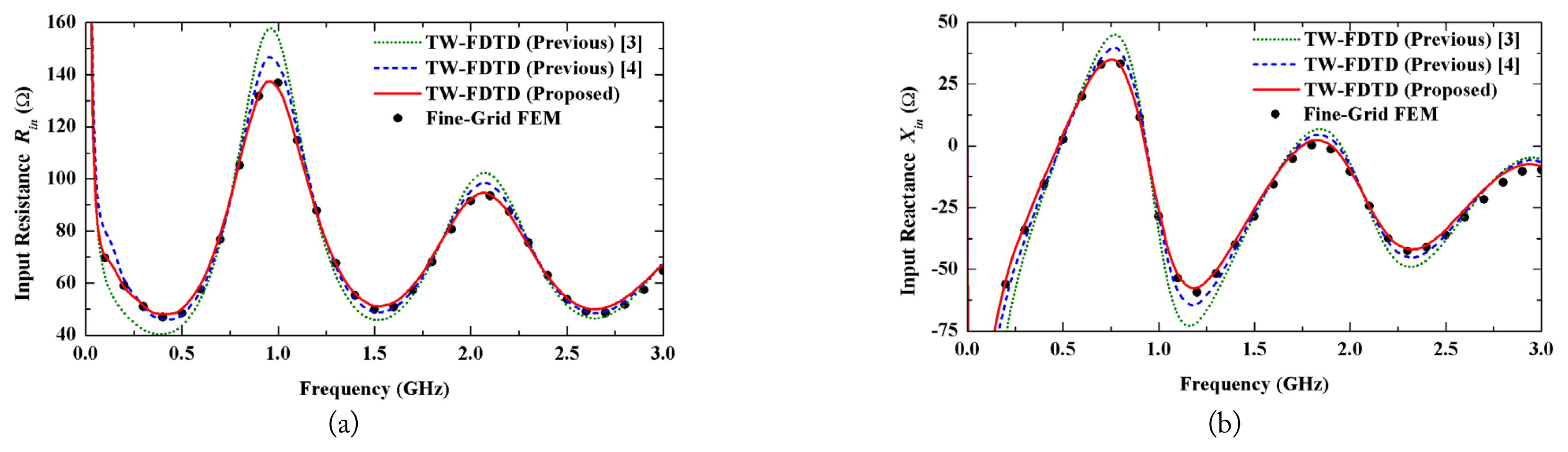
The input impedances of Teflon-insulated cylindrical monopole antennas placed in 15% wet soil: (a) input resistance and (b) input reactance.
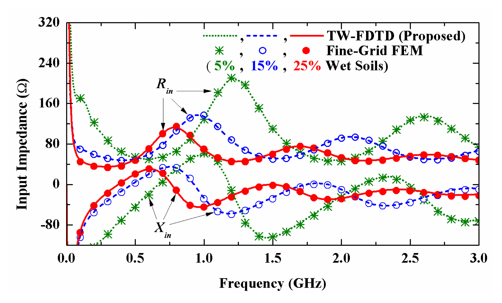
The input impedances of Teflon-insulated cylindrical monopole antennas embedded in 5%–25% wet soils.
IV. Conclusion
An improved DTBC formulation for the TW-FDTD modeling of insulated antennas located in lossy media is proposed. The improved DTBC between the insulation and surrounding media was derived from Maxwell’s equations under the LFA over each time step. Then, the DTBC was corrected in the TW-FDTD equations. In a comparative study of the input impedances of Teflon-insulated monopole antennas in wet soils, we show that the proposed approach has higher accuracy than previous techniques.
Acknowledgments
This research was supported by the 2019 scientific promotion program funded by Jeju National University.
References
Biography

Seung-Yeup Hyun received the B.S. degree in telecommunications engineering from Jeju National University, Jeju, Korea, in 1997, and the M.S. and Ph.D. degrees in radio sciences and engineering from Korea University, Seoul, Korea, in 1999 and 2008, respectively. From 2001 to 2003, he was a Staff Research Engineer with the Research and Development Laboratory, SG Technology, Chungnam, Korea. From 2003 to 2006, he was a Senior Research Engineer with the Digital Appliance Laboratory, LG Electronics, Seoul, Korea. From 1997 to 2008, he was a Student Researcher with the Imaging Media Research Center, Korea Institute of Science and Technology (KIST), Seoul, Korea. From 2009 to 2011, he was a Principal Research Engineer with the Ground-Penetrating Radar (GPR) Division, Isung Corporation, Gyeonggi-do, Korea. From 2008 to 2012, he was a Postdoctoral Research Fellow with the Imaging Media Research Center, KIST. Since 2012, he has been a faculty member of the Department of Telecommunication Engineering, Jeju National University, Jeju, Korea, where he is currently an associate professor. His research interests include ultra-wideband (UWB) antennas, microwave imaging, ground-penetrating radar (GPR) systems, and plasma lighting systems.