Improving the Force and Time Response of a DC Solenoid Electromagnetic Actuator by Changing the Lower Core Angle
Article information
Abstract
The aim of almost any electromagnetic actuator development is to increase the electromagnetic force with which an actuator acts on a plunger with as fast a time response as possible while maintaining the dimensions as small as possible. This paper presents research on the impact of the lower core angle on the force and time response of a DC solenoid electromagnetic actuator. The research method is based on the analytical analysis of the magnetic path of the DC solenoid electromagnetic actuator and a comparison with the numerical simulation results. A transient numerical simulation was performed on a 2D axial-symmetric model of the electromagnetic actuator and included simultaneously solving time-dependent partial differential equations of the electromagnetic actuator’s magnetic, electrical, and mechanical subsystems. The magnetic subsystem was analyzed by the finite element method (FEM) using the ANSYS Electronics software package. The three prototype models with different lower core angles were produced and tested in the accredited Laboratory Center of KONČAR Electrical Engineering Institute. The obtained measurements are compared with the analytical results and numerical simulation results.
I. Introduction
A solenoid electromagnetic actuator (EMA) is defined as a device through which magnetic energy changes electrical energy into mechanical energy related to almost linear motion or push/pull force [1]. The typical features of EMAs are their compact size, simple structure [2], cheap production, simple activation, ease of control, and high reliability. Due to this, they have become widely used in many different applications.
The design of EMAs starts with the operating conditions of the device. DC EMAs can work in short- or long-term regimes. The most important characteristic for short-term regimes is the shape of the EMA’s static characteristic, whereas the temperature rise due to the Joule losses produced by the current is the most common limitation for long-term regimes. DC EMAs usually need to achieve a certain force to overcome the initial force of a mechanism [3]. The aim of almost any EMA development is to increase the electromagnetic force with which an actuator acts on a plunger with as fast a time response as possible while maintaining the dimensions as small as possible. The investigation of plunger shape impact on the electromagnetic force of EMAs was started by Roters, who developed analytical force equations for the four main plunger shapes (conical, flat, wedge-shaped and truncated), neglecting the fringing flux and saturation effect [4]. A few more different types of plunger shapes were investigated in [5] using a modeling approach. Plunger shape optimization was conducted using a genetic algorithm-based technique in [1, 6]. A shape optimization of coil and core using a genetic algorithm approach was performed in [7–9]. The coil design parameters based on the magnetic flux leakage were observed in [10]. The speed-increasing method of solenoid EMAs using a non-magnetic ring has been presented in [11]. Since the coils are the main constructional elements of an EMA, the coil parameter selection process is a prerequisite to building an efficient device. The selection of coil parameters in terms of the coil’s dimensions and number of turns are investigated in [12]. The impact of the coil winding angle on the force of DC solenoid electromagnetic actuators has been studied in [13]. The shape of the upper core, specifically control cone length and slope, has been investigated in [14]. However, none of these papers investigated the improvement of the electromagnetic force characteristics and time response of DC solenoid EMAs by changing the lower core angle.
This paper presents research on the impact of the lower core angle on the electromagnetic force and time response of a DC solenoid EMA. An analytical analysis of a DC solenoid EMA’s magnetic path has been developed. A transient numerical simulation was performed on the 2D axial-symmetric model of the EMA using the ANSYS Maxwell software package. The numerical simulation model includes simultaneously solving time-dependent partial differential equations of the EMA’s magnetic, electrical, and mechanical subsystems, whereas its magnetic subsystem is analyzed by FEM. The laboratory testing measurements of EMAs with different lower core angles are compared with the analytical and numerical simulation results.
II. Work Principle and Mathematical Formulation
The general structure of a DC solenoid EMA is shown in Fig. 1. It consists of a coil, plunger, non-magnetic shaft, upper core, non-magnetic ring, spring, lower core, non-magnetic plate, and air gap (Table 1).

The 2D axial-symmetric model of a DC solenoid EMA.
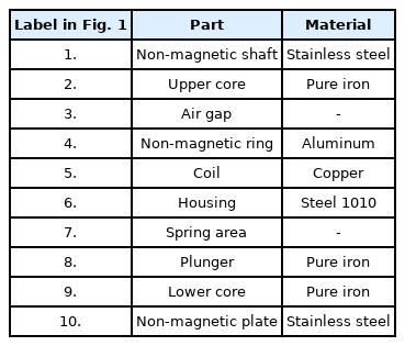
DC solenoid EMA parts
A magnetic circuit comprises the lower and upper core, housing, and plunger. The electromagnetic force acting on the plunger is generated in the air gap, the site of energy conversion. The coil provides electrical resistance. The plunger position is initialized by the non-magnetic plate, while the spring returns the plunger to the initial position after activation [9, 13].
The activation response of a DC solenoid EMA consists of three common periods: a sub-transient period, transient period, and stopping period [3]. In the sub-transient period, the excitation voltage is applied, yet there is still no plunger movement. The magnetic flux flows through the magnetic path and builds electromagnetic force. When the electromagnetic force value overcomes the return spring’s initial force, the plunger starts to move, and the transient period begins. The plunger movement causes changing magnetic flux in the EMA. Electromotive force, which opposes the voltage source and causes the current to drop, is induced in the coil due to the change in linkage magnetic flux [1]. After the plunger stops its movement, the stopping period begins (the EMF retreats and the current continues to increase).
1. Analytical Model
In this paper, a solenoid EMA is observed as a magnetic circuit, and due to this, it can be described using Ampere’s and Hopkinson’s laws. If the same current flows through all the turns, Ampere’s law can be written as follows [10]:
where H is the magnetic field strength, Ii are the currents flowing in the N windings, B is the magnetic flux density, μ is the permeability of the magnetic material, Φ is the magnetic flux, and S is the area crossed by the magnetic flux. Assuming that all the magnetic flux remains contained inside the EMA, it can be considered as a constant. Since there are two types of materials along the path of integration (magnetic material and air) and considering reluctance,
where ℜm is the magnetic material reluctance and ℜa is the air gap reluctance. The reluctances are represented by the following equations:
where lm is the length of the path along the magnetic material,
From the definition of the Maxwell Stress Tensor and the properties of the Kronecker delta along with the fact that the magnetic field B has only y component (Fig. 1), it is possible to write the electromagnetic force acting on the plunger of the EMA as [15]:
By combining Eqs. (8) and (10), the final equation for electromagnetic force (Fe) is obtained:
The cross-section area of the plunger can be obtained using the following equation:
where rpo is the plunger’s outer radius and rnms is the radius of the non-magnetic shaft. The length of the path along the ferromagnetic material (Fig. 2) is calculated using the following equation:
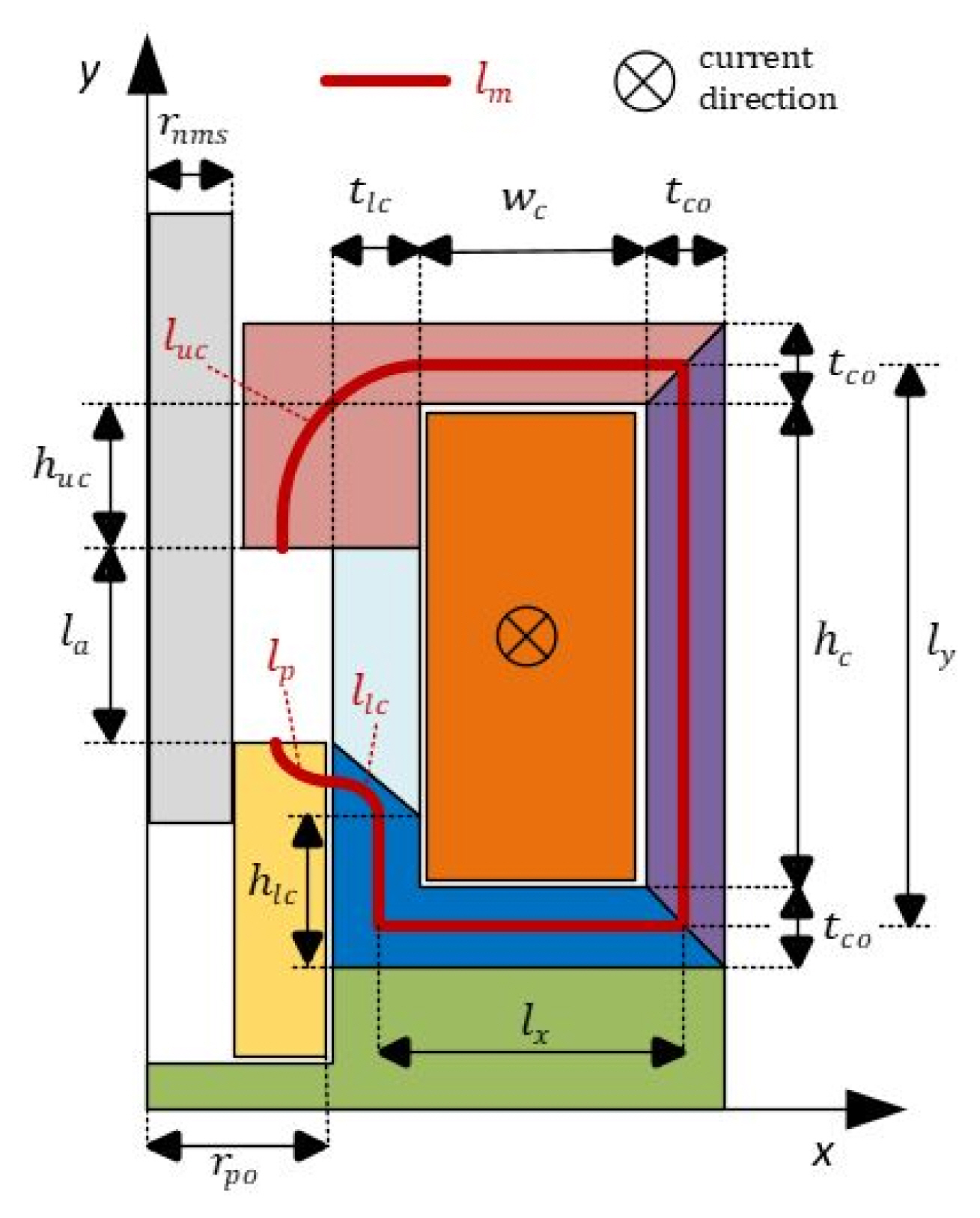
Design variables overview.
with the following notations: lx,ly is the paths along the magnetic material in the x and y direction; hlc is the height of the lower core; llc is the length of the path along the angled part of the lower core; lp is the length of the path along the plunger; llc is the length of the path along the upper core; wc is the coil width; and tco is the thickness of the core.
The magnetic path length along the angled part of the lower core (llc) and the magnetic path along the plunger (lp) are calculated using the expression for ellipse arc length. The equation of the ellipse in the Cartesian coordinate system with the major axis along the x-axis, whose length is 2a, and with the minor axis along the y-axis, whose length is 2b, is:
The expression for computing the arc length of any curve given by the parametric equations (x=f(t),y=f(t)) over the range c≤t≤d is given as [16]:
In this case, the range is the first quadrant (0≤t≤π/2). The following ellipse parametric equations and their derivations are used:
By combining (15) with (16) and (17), the final equation for ellipse arc length in the first quadrant is obtained:
This can be further rewritten using cos2t=1−sin2t:
The obtained complete elliptic integral of the second kind is one of those integrals that cannot be expressed in a closed form in terms of the familiar functions of calculus, except if k=0 (circle). For the purpose of analytical calculation of the ferromagnetic path length along the angled lower core, Kepler’s approximation is used [16]:
Using the above expression, the length of path along the angled part of the lower core (llc) and the length of path along the plunger (lp), both shown in Fig. 3, are calculated:

The plunger and lower core (zoomed detail).
The length of path along the upper core, using (20), is approximated by the following equation (Fig. 2):
When (22), (23), and (24) are put in (13), the total length of the magnetic path through the EMA is obtained by the following equation:
By combining Eqs. (11) and (25), the final equation for electromagnetic force (Fe) acting on the plunger is obtained.
2. Numerical Model of EMAs
The numerical model of an EMA is represented by three nonlinear systems (magnetic, electrical, and mechanical), which are mutually coupled and solved concurrently. Maxwell’s equations are a set of four differential equations that form the theoretical basis of electromagnetism. They describe time- and space-dependent solutions, and they are used to solve the EMA’s magnetic subsystem [12]. The vector potential A has only one component, and that scalar function depends on two space variables (r, z) and time (t) when dealing with axially symmetric geometry [1]. The EMA’s magnetic subsystem is represented by the following time-dependent differential equation [17]:
where Aϕ is the circular component of the magnetic vector potential, Sc is the cross-section area of coil, σ is the electric conductivity, and v is the plunger velocity. The EMA’s electrical subsystem is described by the following equation:
where u is the applied voltage and R is the coil resistance. The EMA’s mechanical subsystem is represented by Newton’s second law, whereby the plunger movement is described as follows:
where m is the plunger mass, β is the damping coefficient, v is the plunger velocity in z direction and Fl is the load force. The plunger velocity in z direction is given as:
The electromagnetic force calculation was performed in every time step using the magnetic energy change equation [17]:
where W is the magnetic energy, H is the magnetic field strength, and V is the volume of the EMA. The electromagnetic calculation was conducted using ANSYS Maxwell and ANSYS Simplorer software (Fig. 4).
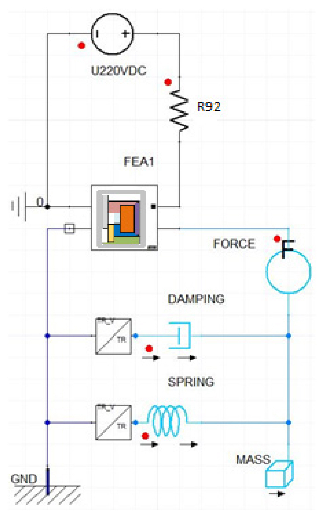
The model of EMAs in ANSYS Simplorer.
III. Simulation Results Analysis
Five different models of solenoid EMA were simulated overall. Plunger shape and mass (m=18 g), applied DC voltage (U=220 V), and coil resistance (R=92 Ω) are common to all the simulated models. On the outer edges of all the simulated models, Dirichlet’s boundary conditions for the magnetic field (Aϕ=0), have been applied. This constraint causes the magnetic flux to be tangential at the edges of the model, keeping it within the simulated region. Based on the maximum current that can be interrupted (2.5 A), the coil resistance and the required number of turns have been calculated.
To the modeled motion area containing the plunger, the moving mesh was applied. The mesh size elements should be small enough to prevent significant element deformation, which can have a serious impact on the solution’s accuracy due to the magnetic flux density calculation error in the vicinity of the plunger. The variable spring force is modeled as a function of the plunger displacement, to which is added the preload spring force (F1=0.5 N), thus making the total load force (Fl):
where k is the spring constant and z is the plunger displacement. The total duration of the simulation is set to 10 ms, whereas the simulation time step is set to 0.02 ms. The impact of the lower core angle on the electromagnetic force, inductance, and time response of EMAs was observed at angles of 0°, 20°, 40°, 50°, and 60°. The numerical simulation results of the electromagnetic force dependent on the lower core angle and coil current, as well as inductance and dependency on time, are illustrated in Figs. 5–7 and in Table 2.
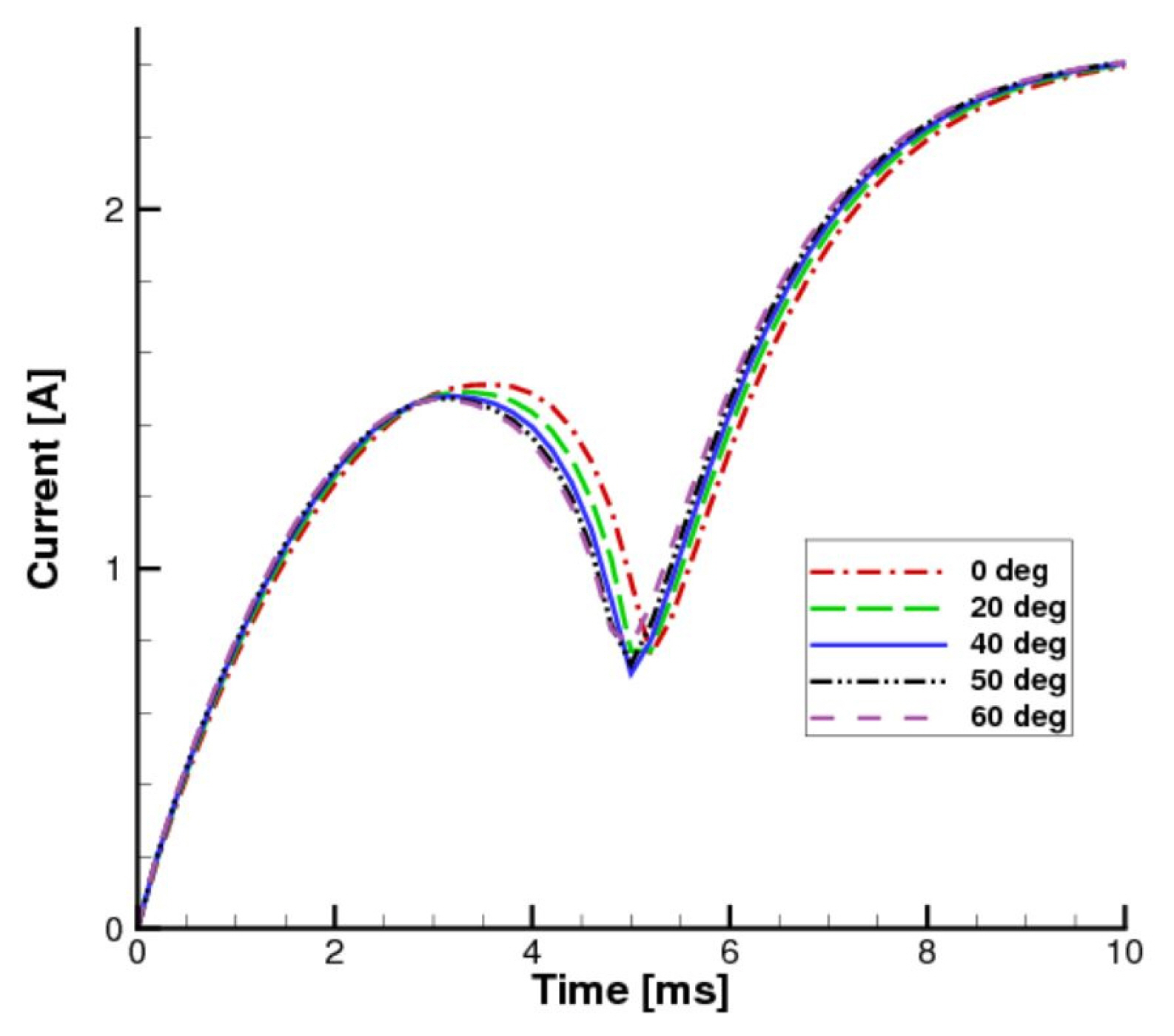
Numerical simulation results of lower core angle’s impact on current.
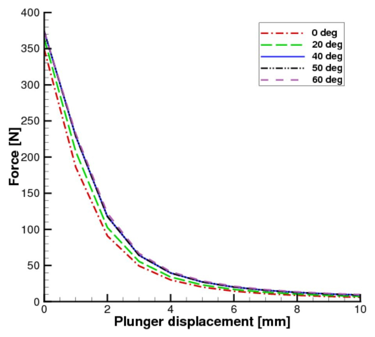
Numerical simulation results of lower core angle’s impact on attraction force.

Numerical simulation results of lower core angle’s impact on inductance.
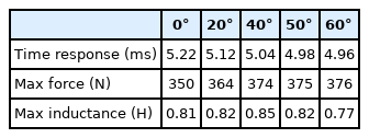
Numerical simulation results of lower core angle’s impact on EMA characteristics
The magnetic flux density distribution in EMA at 3.2 ms for lower core angles of 0°, 20°, and 40° is shown in Fig. 8. The plunger velocity and position relative to the plunger starting point are higher if the lower core angle is higher. At 3.2 ms, the lower core with a 40° angle has a velocity of 5.67 m/s and position of 4.7 mm, compared to the flat lower core (0°), which has a velocity of 4.37 m/s and position of 3.33 mm.
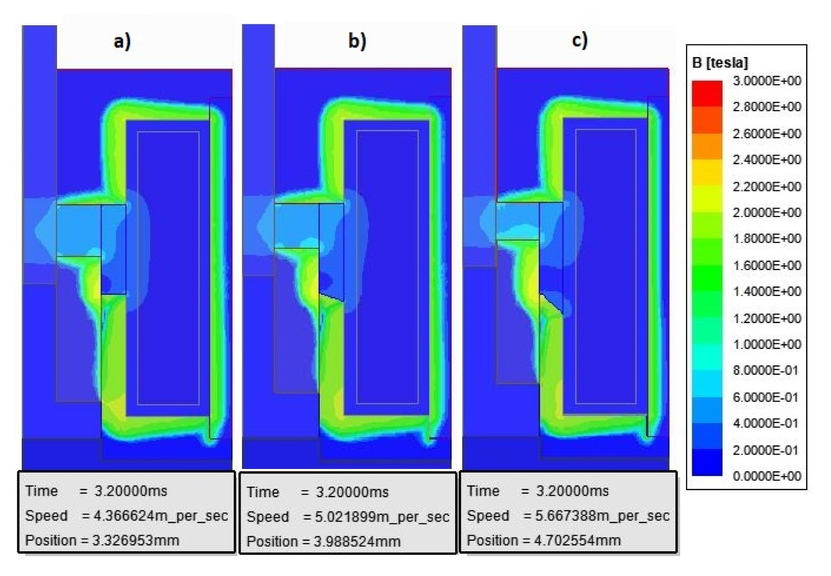
Magnetic flux density distribution in EMAs at 3.2 ms for lower core angle (α) of (a) 0°, (b) 20°, and (c) 40°.
IV. Laboratory Testing
A total of three prototype models with lower core angles of 0°, 40°, and 60° were produced. The flat type of plunger was used for testing procedures in all the prototype models. The properties of tested EMAs are given in Table 3, while the design variables are given in Table 4.

EMA properties
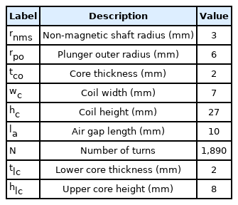
EMA design variables
The prototype models were tested in the accredited Laboratory Center of KONČAR Electrical Engineering Institute. Coil resistance, current, and electromagnetic force were measured. A standard multimeter, FLUKE 289 IMSK, was used to measure coil resistance. The programmable DC power supply TDK Lambda Genesys 300-11 was used to power EMAs. A National Instruments TR12K transient recorder with a sample rate of 20 MS/s and its acquisition unit were used to measure coil current precisely. The electromagnetic force measurement method was improved compared to [2]. The electromagnetic force acting on the plunger was measured using the universal machine for testing materials: ZwickRoell Z020. To determine the electromagnetic force value, the load cell ZwickRoell Type XForce HP with sensitivity of 2 mV/V, having a linear characteristic for measurement in range from 0 to 500 kg, was used. The load cell has a measurement accuracy of ±2% within this range. Before the force measurement process, the top of the machine extension attached to the load cell was set at a distance of 1 mm from the top of the plunger in its final position. Since the tested prototypes were short-term regime type, the head velocity of the material testing machine was set to vtm = 1 mm/s to prevent the EMAs from overheating during the testing. The load cell moved together with the material testing machine head, reading the electromagnetic force value along with its movement (Fig. 9).
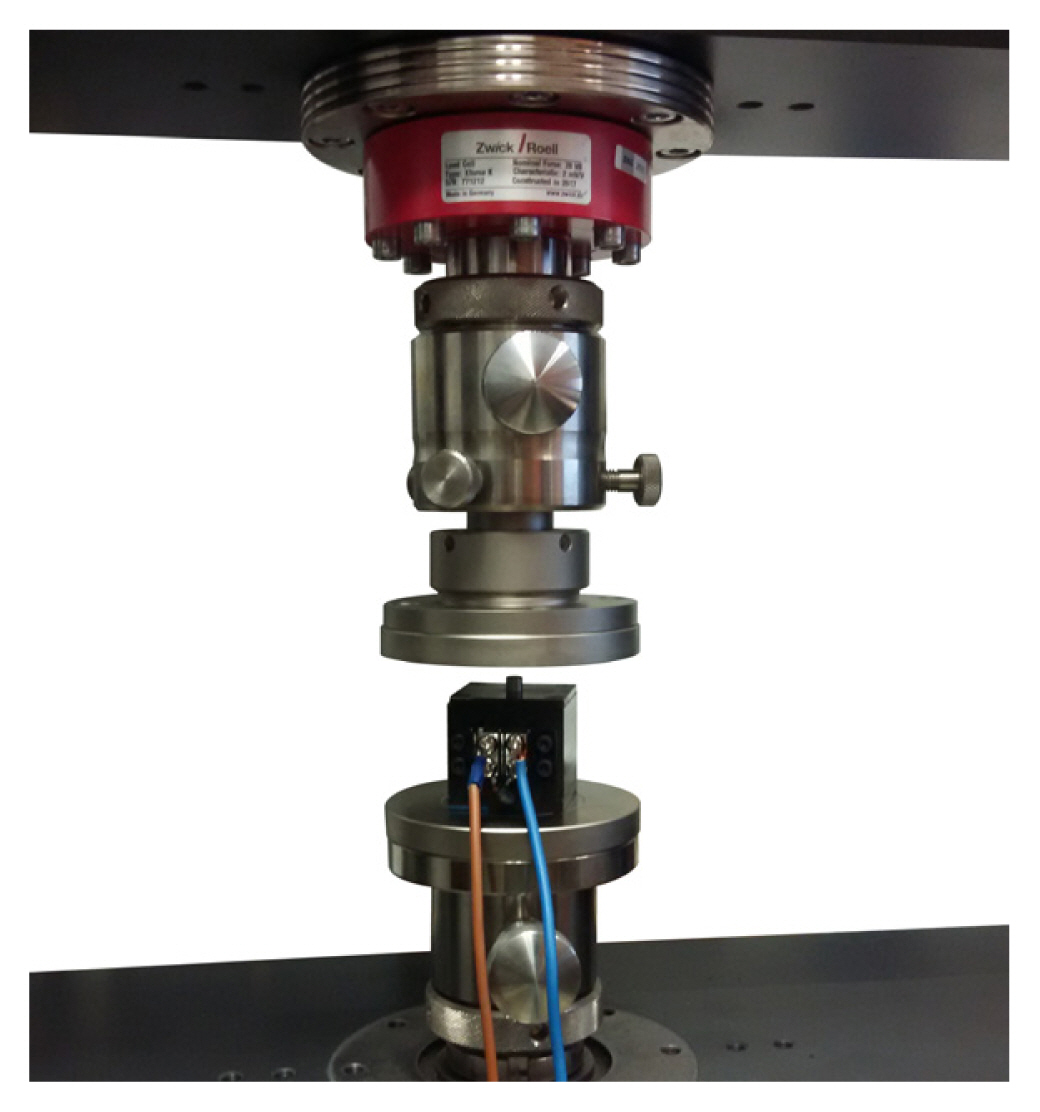
The force measurement process.
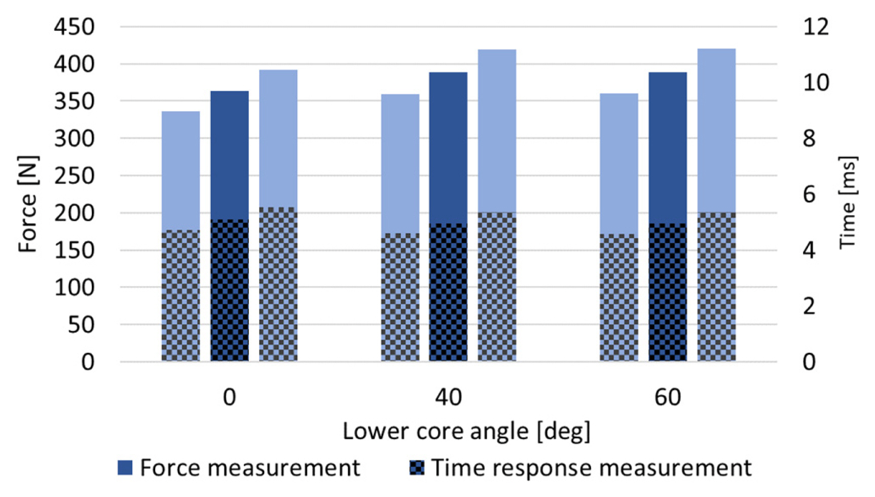
The measurements showed that by changing the lower core angle, the electromagnetic attraction force acting on the plunger could be increased by 7.1%, from the initial 363.35 N to 389.14 N, while at the same time, the EMA’s time response is reduced by 2.94%, from 5.11 ms to 4.95 ms (Table 5 and 6, Figs. 10–12).
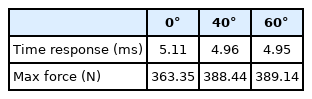
Measurement results of the lower core angle’s impact on EMA characteristics
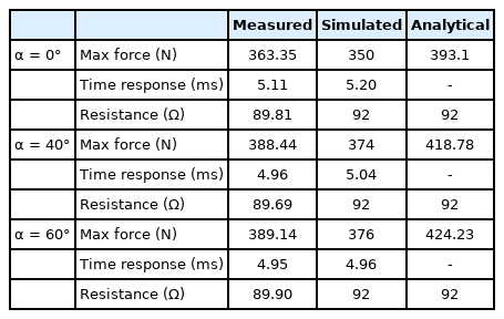
Comparison of measurement, simulation, and analytical results
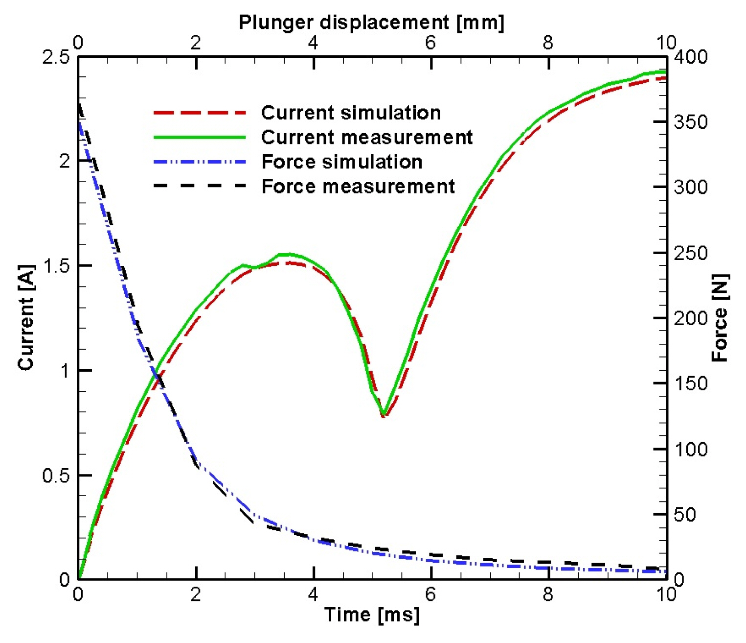
Measurements and numerical simulation results comparison for angle α = 0°.

Measurements and numerical simulation results comparison for angle α = 40°.

Measurements and numerical simulation results comparison for angle α = 60°.
V. Results Comparison
Table 6 shows a comparison of measurements, numerical simulation results, and analytical results. The results show that the maximum electromagnetic force of the solenoid EMA increases as the lower core angle increases.
Considering the influence of the lower core angle on the response time of EMA, the numerical simulation results, as well as the analytical and measurement results, reveal that the time response of solenoid EMAs is faster if the lower core angle is higher (Table 6).
The maximum deviation between the simulated and measured values of the electromagnetic force is 3.86% for a lower core angle of 40° (Fig. 13). Concurrently, the maximum deviation between the simulated and measured response time is 1.76% at a lower core angle of 0° (Table 6). The total measurement uncertainty is shown in Fig. 14, and it is ±8%.
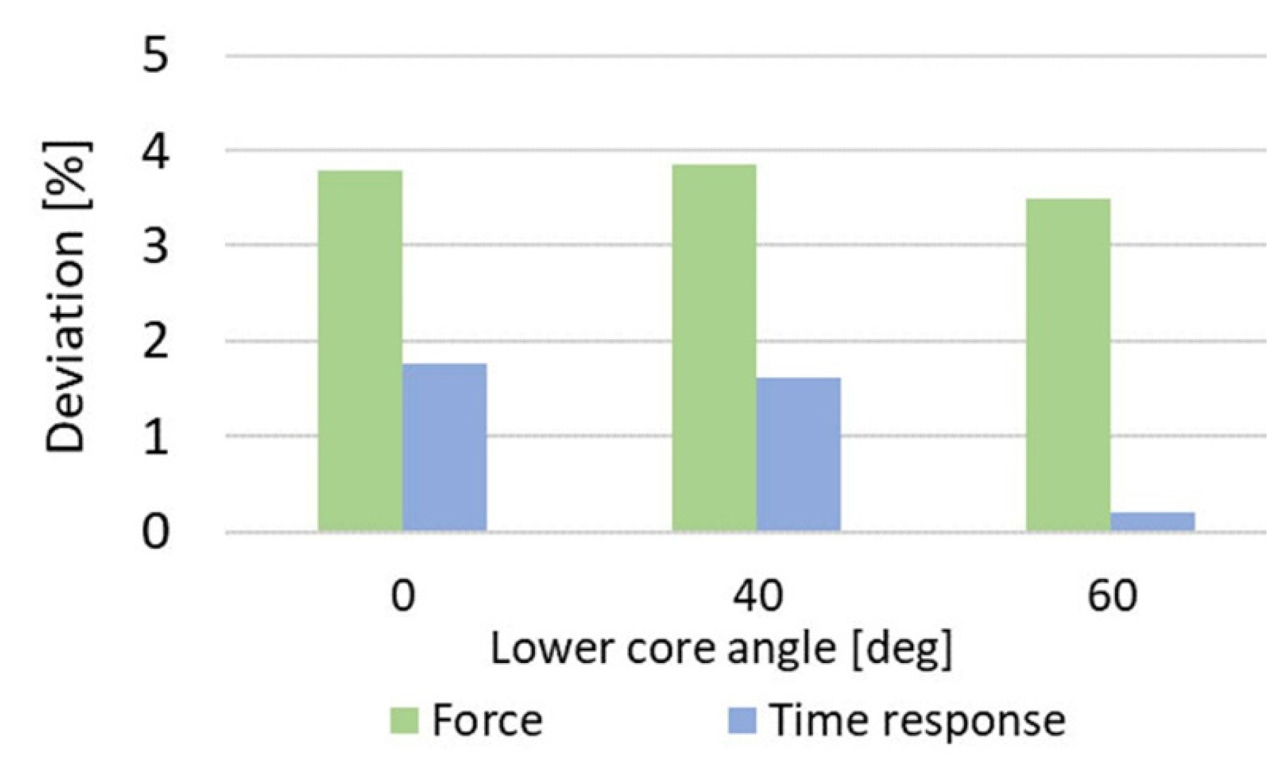
Deviation between numerical simulation results and measurements.
Measurement uncertainty, ±8%.
VI. Conclusion
The aim of almost any electromagnetic actuator development is to increase the electromagnetic force with which an actuator acts on a plunger with as fast a time response as possible while maintaining the dimensions as small as possible.
This paper has presented research performed on the impact of the lower core angle on the electromagnetic force and response time of a DC solenoid EMA, which is based on a magnetic path analysis. The measurements, numerical simulation results, and analytical results were compared.
Numerical simulation results showed that, by increasing the lower core angle from 0° to 60°, it is possible to increase the maximum electromagnetic force by 7.43% while, at the same time, reducing the response time by 4.6%. The three prototypes with lower core angles of 0°, 40°, and 60° were produced and tested in an accredited Laboratory Center at KONČAR Electrical Engineering Institute.
Measurements were taken of the EMA’s electromagnetic force and response time. The maximum deviation between the simulated and measured values of the electromagnetic force was 3.86%, whereas the maximum deviation between the simulated and measured response times was only 1.76%. The analytical method presented yields a maximum deviation of 9.02% compared to the measured values of the electromagnetic force, and therefore, it can be concluded that it is suitable for the rapid calculation of maximum electromagnetic force.
References
Biography

Eduard Plavec was born in 1988 in Zagreb, Croatia. He received a Ph.D. degree in electrical engineering and computing from the University of Zagreb, Faculty of Electrical Engineering and Computing, in 2018. He joined KONČAR Electrical Engineering Institute in 2014. Currently, he is the head of the Research and Development section in the Switchgear and Controlgear Department. His areas of interest include computational electromagnetics and high-voltage engineering. He is a member of CIGRÉ study committee A3—Transmission and Distribution Equipment, an IEEE member since 2012, and an ACES member since 2016.

Miroslav Petrinić was born in Zagreb, Croatia, in 1983. He received a B.Sc. degree in 2007 at the University of Zagreb, Faculty of Electrical Engineering and Computing, where he also received his Ph.D. degree in Electric Machines, Drives and Automation in 2019. Since 2007, he has been employed at KONČAR Electrical Engineering Institute, Inc. in Zagreb. There he works as an R&D engineer in the field of electromagnetism. His scientific research activities are aimed at the analysis and development of electromagnetic devices. He is a coauthor of several papers published in proceedings of scientific and expert conferences and gatherings in the country and abroad. He is a member of the HRO CIGRÉ A1 committee for rotating machines.

Mladen Vidović was born in Zagreb, Croatia. He received a B.Eng. degree from the University of Zagreb, Faculty of Electrical Engineering in 1984. He has worked at KONČAR Electrical Engineering Institute since 1986 in the Switchgear and Controlgear Department, where he is currently the Head of Research and Development. His areas of interest are design and diagnostics of high-voltage switchgears and development of online monitoring systems of high-voltage apparatuses. He is the author of several papers and patents.