I. Introduction
Microwave remote sensing of EarthŌĆÖs terrain using satellite synthetic aperture radar (SAR) provides us valuable information nowadays. There are many SARs at C- and X-bands, such as SENTINEL-1(A and B) and RADARSAT-2 at the C-band and TerraSAR-X/TanDEM-X, COSMO-SkyMed(1, 2, 3, 4), and KOMPSAT-5 at the X-band. Therefore, in this study we focused on the C- and X-bands, and also on farming fields and rangelands that microwaves at C- and X-bands can penetrate through their vegetation canopies.
The radiative transfer (RT) technique has been widely used for microwave backscattering from vegetation fields [1, 2]. The radiative transfer model (RTM) has a relatively good accuracy for estimating the backscattering coefficients for a wide range of vegetation canopies [3, 4]. In the RTM, the phase matrix should be accurately calculated for a scattering particle with given incident, scattered, and orientation angles in elevation and azimuthal directions (╬Ėi,Žåi; ╬Ės,Žås; ╬Ėp,Žåp) as well as the size of the particles relative to the wavelength [1].
The phase matrix is obtained from a scattering matrix [S] that is calculated assuming that a leaf is a dielectric lossy flat rectangular or circular plate. The RTM may need to be examined further in terms of the effect of the curvature of a leaf on the radar backscatter to be more practical for applying this model to the determination of the backscattering coefficients of vegetation canopies. The effect of curvature on the radar backscatter is quite large for backscattering from a curved dielectric sheet at C- and X-band frequencies [5, 6]. Therefore, we may need to examine in detail the effect of the leaf curvature on the RTM.
The first-order vector RTM does not include the higher-order multiple scattering among scattering particles in a vegetation canopy. The cross-polarized backscattering coefficient (
Although the backscattering from a bare soil surface can be accurately computed with theoretical and empirical models such as the integral equation method (IEM) [9] and polarimetric radar inversion for soil moisture (PRISM) [10], the reflection from a rough soil surface needs to be examined in more detail, because the microwave interaction between the vegetation canopy and the underlying soil surface mainly depends on the soil-surface roughness in addition to the soil moisture. We may need to redefine the surface roughness for microwave reflection in a different scale (small roughness) in comparison with the surface roughness for microwave backscattering (large roughness).
In this paper, we first examine the RTM for the effect of the leaf curvature in a vegetation canopy, the multiple-scattering effect for vv-, hh-, and vh- (hv-) polarization combinations, and the effect of the surface roughness on the reflection coefficient of an underlying soil surface. Then, the RTM is modified with the optimized input parameters in relation with the leaf curvature, the higher-order multiple scattering, and the small roughness of underlying surface. Finally, the accuracy of the modified RTM is verified by comparing it with experimental data sets.
II. Examination of RTM
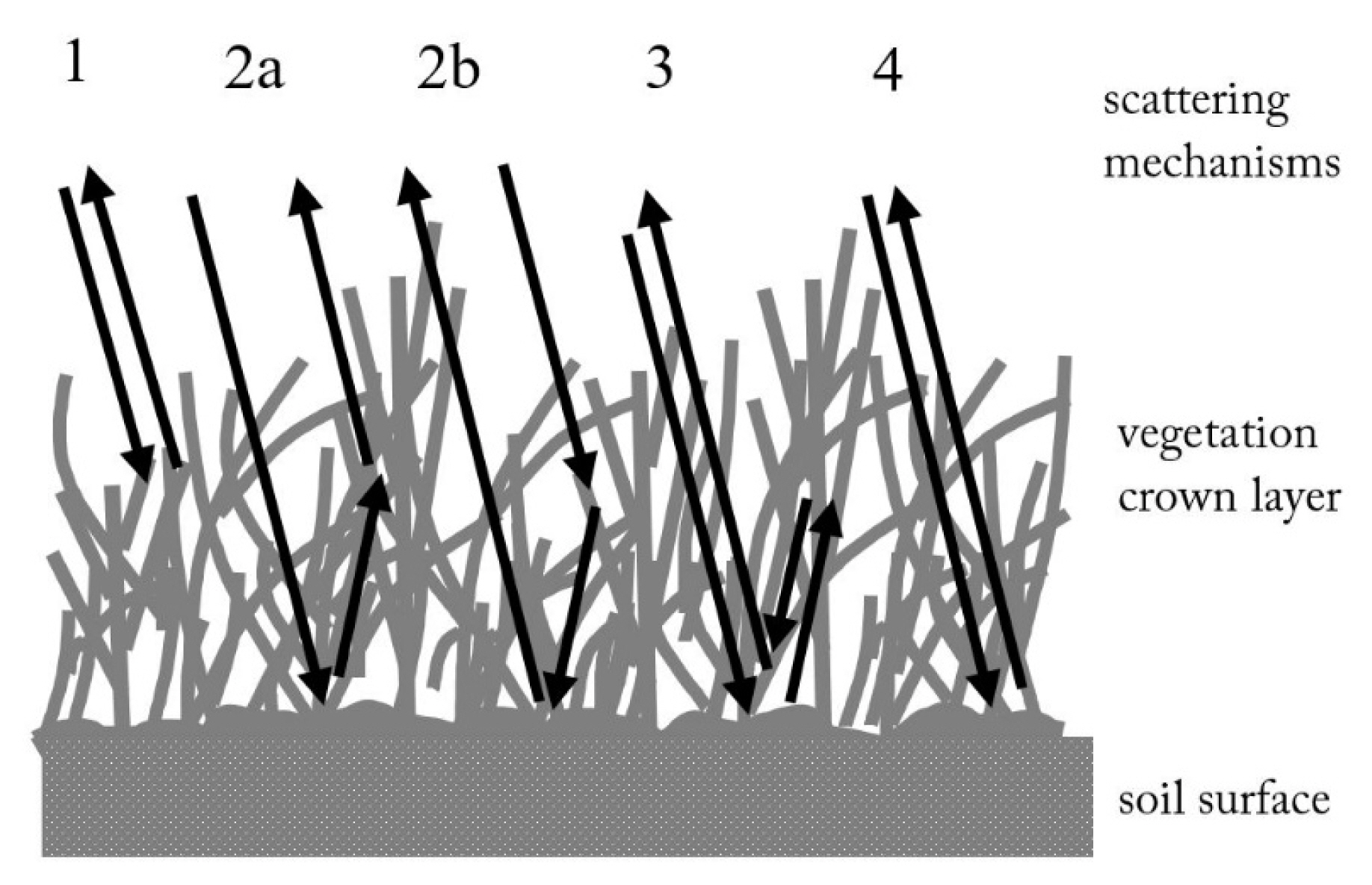
The first-order RTM is a well-known theoretical model for radar backscattering from a vegetation canopy over an underlying soil surface, especially for range and farming fields, as shown in Fig. 1. In general, the RTM includes five scattering mechanisms:
(1) the direct backscatter from the vegetation layer,
(4) the direct backscatter from the underlying soil surface with the attenuation through the vegetation layer, and
(2)ŌĆō(3) the interactions between the vegetation layer and the underlying soil surface: i.e.,
(2a) incidence ŌĆō reflection from the ground ŌĆō forward scattering from the vegetation layer ŌĆō backscatter,
(2b) incidence ŌĆō forward scattering from the vegetation layer ŌĆō reflection from the ground ŌĆō backscatter, and
(3) incidence ŌĆō reflection from the ground ŌĆōbackscattering from the vegetation layer ŌĆō reflection from the ground ŌĆō backscatter.
Then the backscattering coefficient of a vegetated surface can be computed by the following summation of the five scattering mechanisms:
where the first four terms can be formulated with scattering matrices of vegetation particles such as lossy dielectric disks for leaves and lossy dielectric cylinders for stems and branches [1ŌĆō3]. The last term of Eq. (1) can be obtained from a theoretical or empirical model for microwave backscattering from soil surfaces [9, 10].
Eq. (1) can be explicitly expressed in the following form:
where p or q denotes v- or h-polarization, m or n is 1 or 2, and vv-, vh-, hv-, and hh-polarizations correspond to 11, 12, 21, and 22 elements of the 4├Ś4 transformation matrix
T ¯ ¯ A ¯ ¯ E ¯ ¯ D ¯ ¯ R ¯ ¯ M ¯ ¯ P ¯ ¯
(3)
where
[ A ┬» ┬» kl ] ij = [ E ┬» ┬» k - 1 P ┬» ┬» kl E ┬» ┬» l ] ij ŌĆē C kl , ij
The subscripts k = 1, 2, 3, 4, and 5 of the transformation matrix
T ¯ ¯ k P ¯ ¯ S ¯ ¯ S ¯ ¯ M ¯ ¯
1. Effect of Leaf Curvature
There are various shapes and sizes of leaves in rangelands and farming fields, such as blade-type and disk-type lossy dielectric leaves. Those natural and agricultural leaves usually have curved shapes and/or irregular surfaces. The reduction of radar cross section (RCS Žā) of a curved dielectric sheet can be analytically computed accurately by multiplying a curve factor to the scattering matrix of a flat dielectric disk, using a Fresnel integral with the argument of leaf length a and the radius of curvature Žü for a given frequency [6].
where Sc is the scattering matrix element for a curved lossy dielectric sheet, Sfp is the scattering matrix element for a flat plate, F(╬│) is the Fresnel integral with an argument ╬│, and k0 is the wavenumber. For example, the reductions of RCS at normal incidence are about 0.98, 0.75, and 0.4 in magnitude for L-, C-, and X-bands, respectively, when both the curvature radius and leaf length are 6 cm. The RCS reductions are 0.95, 0.75, and 0.32 for the curvature radii of 12, 6, and 3 cm, respectively, with a fixed leaf length of 6 cm at the C-band [6]. Therefore, we need to multiply a multiplicative factor, i.e., the ŌĆ£curve factorŌĆØ Cfactor, to the scattering matrices for leaves and stems to compensate for the RCS reduction because of the leaf-curvature effect in the RTM.
where [S]m is the modified scattering matrix of a leaf or a branch.
The curve factor may also cover the RCS reduction that would be caused by the irregularity deviating from the flatness of a leaf.
2. Effect of Multiple Scattering
The RTM does not include the higher-order multiple scattering as shown in Fig. 1, whereas the actual microwave backscatter will include the higher-order multiple scattering inside the vegetation layer and between the vegetation layer and the underlying ground surface. A full-wave analysis by the moment method for a relatively sparse vegetation field revealed that the effect of multiple scattering is negligible for co-polarization, whereas the cross-polarized backscattering coefficients are significantly influenced by the effect of multiple scattering [8]. For example, the difference between a full-wave analysis that includes all orders of multiple scattering and a theoretical model that includes only single scattering is about 9 dB for hv-polarization and less than 0.5 dB for hh-polarization for a sample vegetation canopy with only ten 2╬╗-length stems on a 2╬╗-diameter underlying surface [8]. The fully phase-coherent computation [11] for the backscattering coefficients of grasslands also showed that the higher-order scattering terms should be added to fit the radar measurements for the cross-polarized data [12].
The effect of multiple scattering can be accounted by multiplying a factor, the so-called ŌĆ£multiple factorŌĆØ Mfactor, to the transformation matrix elements for the higher-order multiple scattering from scatters in a vegetation layer.
where [T]km is the modified kth transformation matrix, and the multiple factor may be obtained from an extensive database of experimental measurements.
3. Effect of Surface Roughness
For the backscattering from an underlying soil surface, the microwave radiates from an antenna of a radar far from the rough surface. Therefore, the surface roughness should be considered for the whole antenna footprint that provides a largescale roughness. However, for the reflection from the underlying soil surface in the scattering mechanisms 2a, 2b, and 3 in Fig. 1, the scattering particles are positioned near the surface. Therefore, the area of reflection might be small, which provides a small roughness. The retrieval of the RMS height depends on the length of the surface profile, and the measured RMS height rapidly decreases with a decrease in the profile length of the surface [13, 14]. Therefore, the use of large-scale roughness parameters for mechanism 4 and small-scale roughness parameters for mechanisms 2a, 2b, and 3 can be recommended.
The effect of small roughness would be implemented with the decrease in the RMS height for the computation of the microwave reflection, such as hRMSŌĆōs = roughness factor (Rfactor)├ŚhRMS, where hRMSŌĆōs is the small-roughness RMS height for reflection, and hRMS is the RMS height for backscattering from the soil surface. For the reflection from a rough surface, the following form of the reflection coefficient is used for the reflectivity matrix.
where [R]m is the modified reflectivity matrix, and
with X=2(khRMSŌĆōscos╬Ė)2, where ╬ōsp is the reflection coefficient of a rough soil surface, ╬ōfp is the Fresnel reflection coefficient of a flat plane, the subscript p is the polarization, ╬Ė is the incidence angle, and I0[┬Ę┬Ę┬Ę] is the modified first-kind Bessel function.
III. Modification and Verification of RTM
The parameters of the RTM with regard to the effects of the leaf curvature, multiple scattering, and small roughness can be determined on the basis of comparisons between the measurements and the RTM. There are numerous data sets for radar backscattering coefficients of vegetation fields at the C- and X-bands. However, it is difficult to find the ground-truth data sets that include all input parameters of the RTM, such as the water contents of leaves and stems, the root-mean-square (RMS) height of the underlying soil surface, the volumetric soil moisture content, the height of the vegetation-crown layer, and the averages and standard deviations of leaf length, leaf width, leaf density, leaf thickness, leaf vertical and horizontal angles, stem length, stem diameter, stem density, and stem vertical and horizontal angles. Therefore, we collected the ground-truth data in relation with the input parameters of the RTM as well as polarimetric scatterometer measurement data sets.
1. Experimental Data Sets
The Hongik polarimetric scatterometer (HPS) was used to acquire the full-polarimetric backscattering coefficients of vegetation fields to closely examine the RTM. The backscattering coefficients of a cornfield in Suwon, Korea, were acquired at the C-band and five different incidence angles (20┬░, 30┬░, 40┬░, 50┬░, and 60┬░) from May 29 to July 11, 2013, covering a whole growing season. The HPS is a vector-network-analyzer-based full-polarimetric L-, C-, and X-band scatterometer, and it is calibrated by the differential Mueller matrix calibration technique (DMMCT) [15] with a single calibration target, namely, a trihedral corner reflector. The backscattering coefficients of a bean field in Suwon, Korea, were also collected by the COSMO-SkyMed SAR at the X-band at 40┬░ for hh-polarization during the bean growth cycle from July 22 to September 24, 2010.
We also collected in situ measured ground-truth data for all the input parameters of the RTM on the same days when the radar data were collected. The parameters for vegetation fields were obtained by sampling. The surface roughness parameters such as the RMS height were obtained from surface profiles that were measured with a laser profilometer and a pin profilometer. The leaf-area index (LAI) values were acquired using AccuPAR LP-80 of Decagon Devices Inc., and the soil moisture contents were measured using EC-5 of the same company.
2. Determination of Parameters
By minimizing the root-mean-square error (RMSE) between the RTM and the scatterometer measurements of a cornfield at the C-band, we can obtain optimum curve, multiple, and roughness factors. It was found that the optimized curve factors for considering the effect of leaf curvatures are about 0.7 for leaves and 1.0 for stems at the C-band for scattering from cornfields. The curve factor depends on frequency (or wavelength) [6], and the curve factor becomes about 0.5 for leaves and 0.7 for branches (stems) at the X-band for scattering from soybean fields.
The co-polarized backscattering coefficients that were measured from vegetation fields agree well with the RTM, and consequently, the multiple factor is about 1.0 at vv- and hh-polarizations as determined by the RMSE technique while considering the effect of multiple scattering, which means that the first-order multiple scattering is dominant for the co-polarized backscattering coefficients. However, the RMSE technique provides about 50 for the cross-polarized scattering from the corn fields.
The RMSE technique leads us to the rough factor of about 0.7. The effect of the rough factor is negligible for very sparse and very dense vegetation canopies, because the interaction between the vegetation canopy and the underlying surface in these cases is negligible.
3. Verification
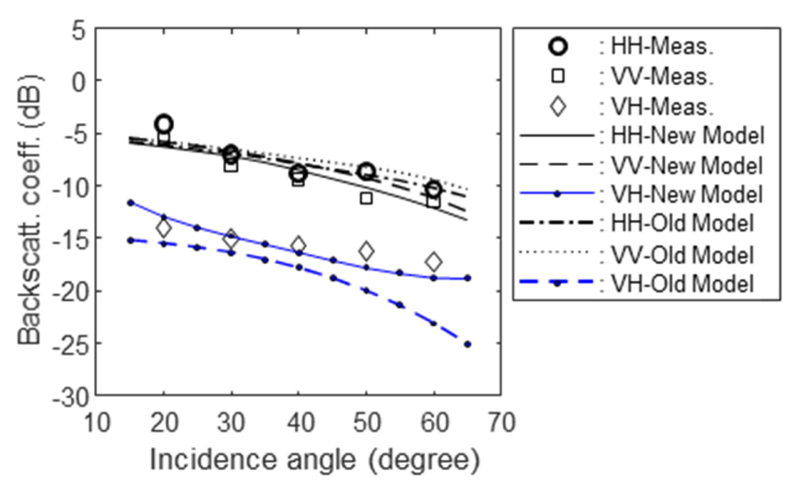
The RTM is modified with the induced parameters from the effects of the leaf curvature, multiple scattering, and small roughness for the reflection, and its accuracy is examined by comparisons between the modified RTM and the scatterometer measurements. Fig. 2 shows the comparison among the scatterometer measurements on May 29, the traditional RTM (ŌĆ£Old ModelŌĆØ), and the new RTM modified with the ŌĆ£curve factor,ŌĆØ ŌĆ£multiple factor,ŌĆØ and ŌĆ£roughness factorŌĆØ as explained in the previous section, and with in situ field-measured 21 input parameters, for multi-polarized backscattering coefficients of the cornfield. The early-stage cornfield on May 29, 2013 was a sparse vegetation field with a plant height of 30 cm and an LAI of 0.48. The backscattering from the underlying soil surface would be dominant in this case. Therefore, the improvement of the modified RTM is minimal for co-polarized backscattering coefficients. However, the cross-polarized backscattering coefficient of the modified RTM is remarkably improved, such as 2.2 dB at 50┬░ and 4.4 dB at 60┬░ as shown in Fig. 2.
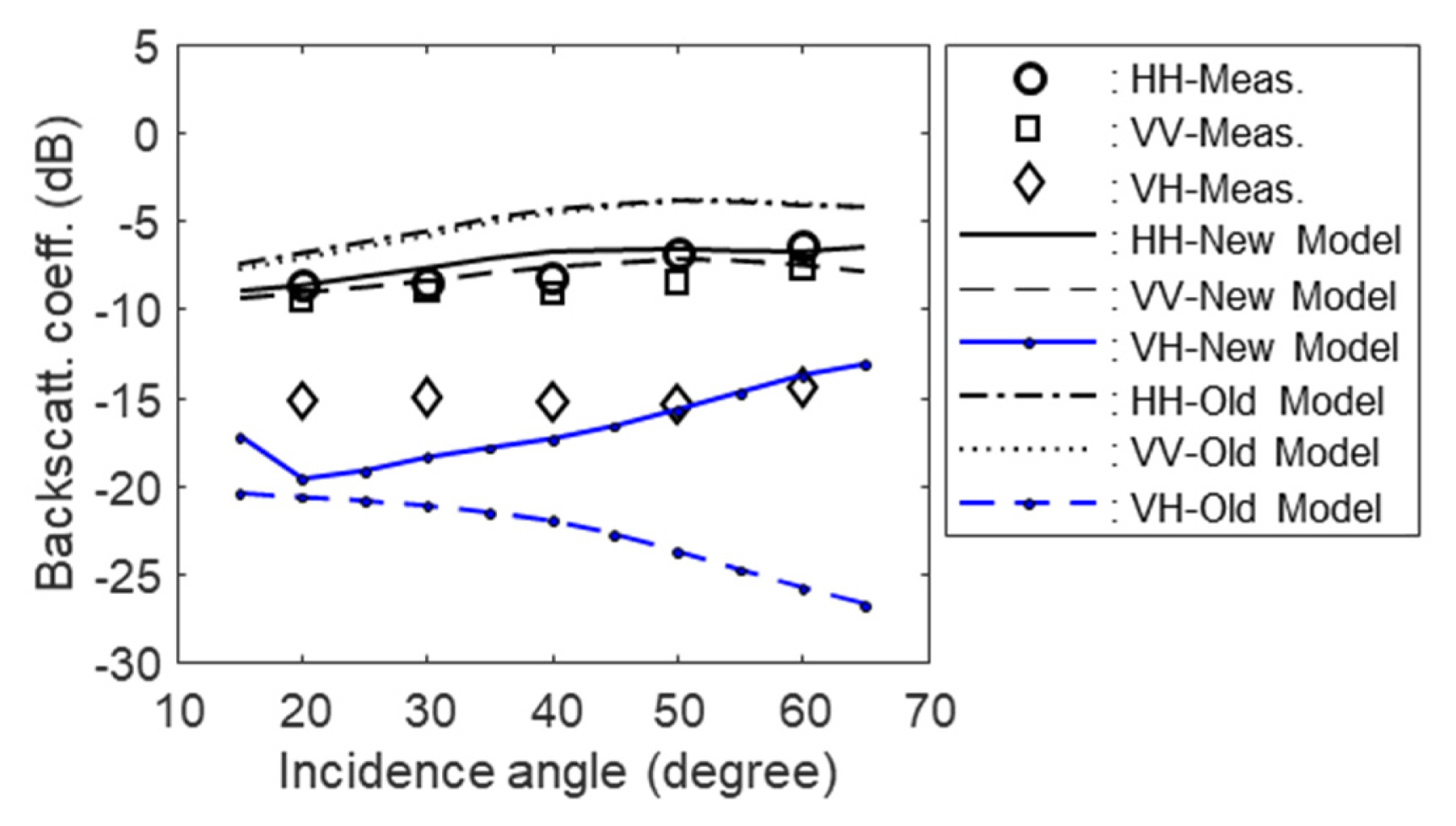
Fig. 3 shows the comparison among the scatterometer measurements on July 11, 2013, the traditional RTM, and the modified RTM for the multi-polarimetric data. The full-grown cornfield on July 11 was a dense vegetation field with a plant height of 250 cm and an LAI of 2.62. Fig. 3 shows that the traditional RTM provided about 2ŌĆō3 dB higher co-polarized backscattering coefficient than the radar measurements without correction for the effect of leaf curvature, whereas the modified model and the measurements agree quite well for the co-polarized backscattering coefficients. The improvement of the cross-polarized backscattering coefficients with the modification for the higher-order multiple scattering is very large as shown in Fig. 3 and Table 1, especially for higher incidence angles, because of (1) the vertical structures of the corn-plant stems and (2) the effective depth increase at higher incidence angles. The discrepancy between the measurements and the modified RTM for vh-polarization at low incidence angles, especially 20┬░ and 30┬░, may be from the fact that the RTM inherently does not include the shape and location of the full-grown leaves.
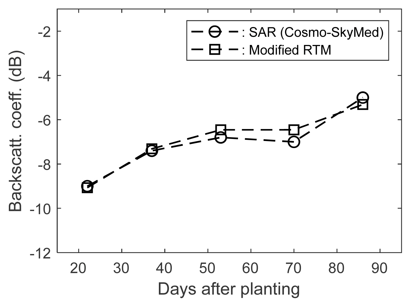
The modified RTM is also compared with the COSMO-SkyMed data at the X-band, which were acquired from a bean field in Suwon, Korea, at 40┬░ for hh-polarization during the bean growth cycle from July to October 2010. The ground-truth data were also collected in situ during the period for about two dozens of input parameters of the RTM. The LAIs of the bean fields were 0.73, 2.42, 3.21, 3.36, and 4.54 for 22, 37, 53, 70, and 86 days after planting, respectively. Fig. 4 shows the comparison between the COSMO-SkyMed data and the modified RTM for the bean field in a growing season. In this comparison, we used a curve factor of 0.5 for leaves and a curve factor of 0.7 for branches and stems, which are lower than the factors at the C-band, because the RCS reduction increases as frequency increases.
There are no changes in the multiple and rough factors: i.e., a multiple factor of 1.0 for hh-polarization and a rough factor of 0.7 for the small-roughness effect.
IV. Concluding Remarks
First, a modified RTM was formulated for estimating the backscattering coefficients of one-layered vegetation fields, and the model was modified on the basis of the HPS measurements and in situ measured ground-truth data for typical agricultural canopies. The modified RTM was multiplied by two multiplicative factors: (1) one is the curvature factor for the curvature effect of leaves and branches (or stems) for all polarizations and (2) the other is the multiple-scattering factor for the cross-polarized backscattering because the cross-polarized backscattering coefficient is very sensitive to the higher-order multiple scattering. In addition to the aforementioned two multiplicative parameters, the small-roughness parameter for microwave reflection from the underlying soil surface was also introduced.