I. Introduction
Microwave heating has been used for a long time in commercial and industrial applications owing to its heating efficiency. A typical example of a heating method using microwaves is a microwave oven at home. It is also used industrially in various fields such as soil moisture removal, volatile organic compound (VOC) removal, disinfection, and sterilization [1–3].
VOCs such as toluene and xylene inevitably occur in many industrial facilities, including semiconductor processing plants, refineries, and shipyards [4]. To prevent environmental pollution and human hazards, VOCs should be filtered by VOC filters. The confinement process of VOCs through filters is called adsorption. Owing to their volatility, the filters used for VOC adsorption can be recycled through microwave heating, and the desorbed VOCs can be separated by an air intake system. This process is called desorption. The adsorption and desorption processes are sequentially performed in separate spaces. To regenerate the VOC filter well, high energy efficiency and heating uniformity are required during desorption.
Since most microwave heating systems are high-power applications, the shielding is very important, and thus, a cavity structure is frequently used. In addition, to avoid dielectric breakdown, the microwave feeding structure often uses a waveguide aperture type composed of a single conductor. For example, a VOC removal facility using a cavity fed by a horn-type microwave feeding structure is suggested [5].
In general, much care is needed for the design of the feeding structure of a cavity since many modes exist inside the cavity as determined by the cavity structure, and the excitation of the mode is dependent on the feeding structure. Many research studies related to this have been actively conducted [6–12]. The optimization process for improving the electric field’s uniformity by analyzing the modes existing in the cavity and expressing the electric field inside the cavity in a linear combination of the modes has been presented [6]. However, modal analysis in a cavity and finding the feeding structure are very difficult because the cavity structures have different characteristics. Another method proposed for improving the uniformity is to use multiple microwave sources with sequential feeding [7]. However, using multiple sources has the disadvantages of system complexity and higher cost. The other method of increasing the uniformity is to employ a mode stirrer to mix multiple electromagnetic modes in the cavity, and parametric studies with a genetic algorithm for a dielectric multilayer in a rectangular cavity were suggested [8, 9]. Nevertheless, the mode stirrer itself is an extra structure that makes the system complicated, and the parametric studies with a genetic algorithm are also difficult to analyze.
There are studies in which dielectric slabs are uniformly heated using a slotted waveguide structure, and studies in which the heating uniformity is improved by using multiple slotted waveguides in a rectangular cavity [10–12]. Unlike the methods introduced earlier, these feeding structures can have the effect of generating multiple microwave sources with a single excitation port in a simple design method. However, the technique was used for heating a dielectric slab and the rectangular cavity only.
In this study, two types of slotted waveguide feeding structures are designed for the uniform heating of a VOC absorbent material in a quadrangular prism-shaped cavity used in a VOC removal facility. This paper is organized as follows. The entire VOC removal system, the cavity structure, and the basic horn-type feeding structure are introduced in Section II. In Section III, the basic theory of waveguide slot and the design method of the two types of slotted waveguide feeding structures are presented. In Section IV, the figure of merit of heating uniformity used in this study is presented, and the comparison result of the heating uniformity performance among the horn-type and the two types of slotted waveguide feeding structures is introduced. The impedance matching characteristics are compared and the load sensitivity is discussed in Section V, followed by the conclusion in Section VI.
II. Entire VOC Removal System and Horn-Type Feeding Structure
Fig. 1(a) shows the entire VOC removal system [4]. The total structure is a large metallic cylinder divided into several cylindrical wedge-shaped rooms, and the red part represents the air intake system. Each room is shielded with metal plates, and the upper and lower surfaces are composed of a metal perforated plate, which shields microwaves, but air can be inhaled. A VOC absorbent material (so-called VOC filter) is partially filled in each room, and microwaves are applied to each room to desorb VOC from the filter. The desorbed VOC is removed by the air intake system, and the system is rotated every certain time to remove the desorbed VOC in other spaces. Owing to the air intake system, microwaves cannot be fed from the top and bottom, but from the outer face of the system or sidewall of the cavity. Fig. 1(b) shows the quadrangular prism-shaped cavity structure for uniform heating used in this study, which is actually a piece of 16 room cavities arranged in circular form in the VOC removal system shown in Fig. 1(a). Table 1 shows the geometric parameters of the cavity. The cavity is partially filled with a dielectric material (VOC filter after adsorption) to be heated, the dielectric constant and loss tangent of which are 4.98 and 0.16, respectively.
Fig. 2 shows a piece of room cavity with the conventional horn-type feeding structure. In this study, two types of slotted waveguide are designed and attached at the sidewall of the cavity to improve the heating uniformity.
III. Two Types of Slotted Waveguide Design
The microwave source used for heating is a magnetron operating at 2.45 GHz. Therefore, the waveguide structure of WR340 (width = 86 mm, height = 43 mm) is selected. The first method (hereinafter, SAWFMfree) is to design the microwave feeding structure according to the well-known broad-wall resonant waveguide slot array (WSA) antenna design method. This method has been used for the uniform heating of a rectangular cavity [12].
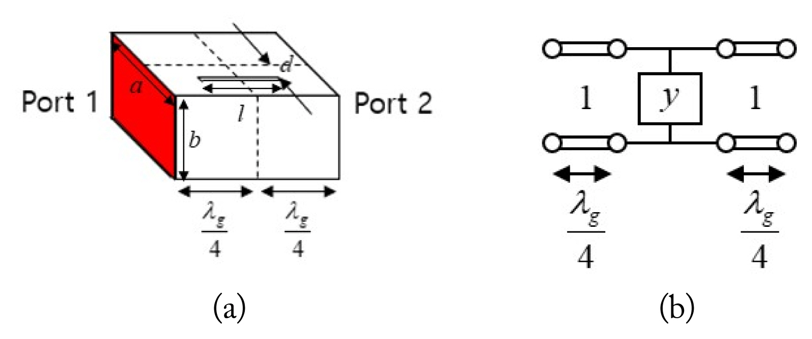
Fig. 3(a) shows a longitudinal slot with an offset on a broad wall of a rectangular waveguide. The slot length is around λ0/2 so that the slot shows a resonance characteristic. Specifically, this structure can be modeled as a shunt admittance element [13–15]. When the TE10 mode is excited in the waveguide, the normalized shunt admittance value can be calculated as
where λg is the guided wavelength in the waveguide [13].
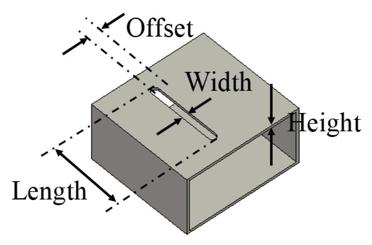
Fig. 4 shows the broad-wall resonant single slot used in this study. Since the admittance value may vary depending on the thickness and width of the slot, a more accurate admittance value can be obtained through full wave simulation. In this study, the slot width and height, shown in Fig. 4, are fixed to 6 mm and 5 mm, respectively. The normalized admittance value can be calculated as
where the normalization factor is a wave impedance of the TE10 mode in the rectangular waveguide. The scattering parameters used in Eq. (2) are the data obtained by simulating the waveguide slot and de-embedding the λg/4 waveguide section on each port. The basic WSA antenna design method uses an equivalent circuit approach where the calculated shunt admittance elements representing broad-wall slots are connected by the transmission line representing the waveguide. For broadside radiation, the slot spacing is set to λg/2, and the offset direction of the adjacent slot is opposite to compensate the phase of the λg/2 waveguide section. The end of the waveguide is short, and the distance from the end to the last slot is λg/4 [13]. Fig. 5 shows the equivalent circuit model of the slotted waveguide structure, and the normalized input admittance can be calculated as
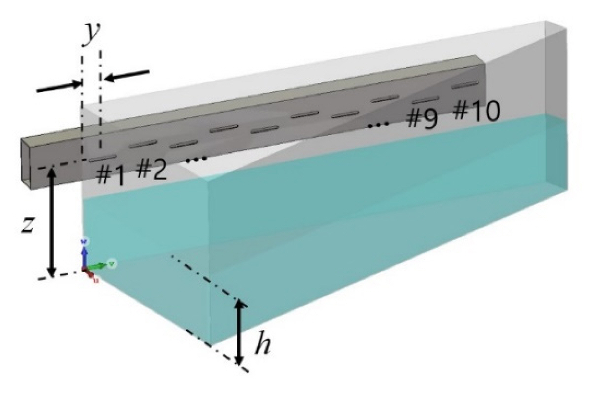
where yk is the normalized admittance value of the kth slot. Considering the overall size of the cavity, the total number of slots is set to 10. Following the broad-side radiation WSA antenna design, the normalized shunt conductance and susceptance value are set close to 0.1 and 0, respectively. The waveguide center is placed at a distance of 235 mm from the floor of the system to avoid direct contact between the VOC absorbent dielectric and the slot. Fig. 6 shows the entire heating system with the slotted waveguide feeding structure, and Table 2 shows the normalized admittance value of each slot and the length and offset properties. The height of the centerline of the slot array and the position of the first slot (#1) are fixed to z = 235 mm and y1 = 42.08 mm, respectively. Also, the quantity of the VOC absorbent material (loading) depends on the operational situation so that the height h is a variable in the range of 130 to 170 mm. The reference h is set to 150 mm, which is an intermediate value of the height range.
For SAWFMfree, the feeding structure is designed using the resonant broad-side WSA antenna design method in free space. However, as soon as the slotted waveguide structure is attached to the sidewall of the cavity, the calculated admittance property is changed by the cavity structure. After all, in order to find the correct admittance data of the slot attached to the cavity, the admittance properties have to be extracted including the effect of the cavity. The second method (hereinafter, SAWFMcavity) is to extract admittance data of the slot including the effect of the cavity and to design the slotted waveguide feeding structure in the same way as the approach in SAWFMfree. In this case, two slots having the same length and offset have different admittances, since the fields excited by the two slots are different depending on the position of the slot inside the cavity. Hence, the position of the slot should be considered as a variable. The height of the centerline of the slot array and the position of the first slot are the same as in the SAWFMfree case. Fig. 7 shows the extracted normalized admittance data with varying lengths and offsets of all slots. Since there are two variables, namely, the slot’s length and offset, the admittance value is calculated by fixing one variable and changing the other variable. Fig. 7(a) and (b) show the normalized shunt conductance and susceptance, respectively, according to the length change when the slot’s offset is fixed at 10 mm. Fig. 7(c) and (d) show the normalized shunt conductance and susceptance, respectively, according to the offset change when the slot’s length is fixed at 58 mm. Notice that the admittance values are quite different depending on the slot’s position as the slot length or offset is large. On the basis of the data in Fig. 7, a slight tuning is performed to match the normalized shunt admittance value of each slot similar to SAWFMfree. Table 3 shows the derived slot’s properties of SAWFMcavity.
IV. Uniform Heating Performance
In this study, to evaluate the heating uniformity performance of various feed structures, an evaluation index related to microwave is suggested. The heat generated in the dielectric is proportional to the power loss density (W/m3) due to electromagn etic waves expressed as
where σ and ɛ″ represent the conductivity of the VOC absorbent dielectric medium and the imaginary part of the dielectric constant, respectively [16]. Although heat transfer should also be considered, only thermal losses due to microwaves are considered in this study. On the basis of the power loss density distribution, the figure of merit for performance evaluation is set as
N: Number of samples
Pi: Power loss density at the i-th sample
P̄: Average value of power loss density
where σnor(P) is the normalized standard deviation of power loss density in the material. To ensure the convergence of the calculation results, the field sampling interval is set to 7 mm, which is smaller than λd/7, where λd is the wavelength in the dielectric medium. The total number of field samples in the dielectric is about 100,000 in this example. To evaluate the heating uniformity of horn-type and proposed systems, full wave EM simulation (CST Microwave Studio) is performed on the conventional horn-type feeding structure and the two WSA models (SAWFMfree and SAWFMcavity).
Fig. 8 shows the power loss density distribution inside the dielectric medium. Fig. 8(a) and (b) show the results for the horn-type feeding structure. Fig. 8(c) and (d) are the results for SAWFMfree, and Fig. 8(e) and (f) are the results for SAWFMcavity. It can be seen that the structure using the horn type has a strong power loss density distribution in the vicinity of the aperture. On the other hand, it can be seen that the power loss density distributions are relatively more uniform in the SAWFMfree and SAWFMcavity cases than in the case of the horn-type structure. The normalized standard deviations are given in Table 4. It is confirmed that the slotted waveguide feeding structure improves the heating uniformity by about 52% compared with the existing horn-type feeding structure. In addition, notice that there is little difference (less than 1%) in heating uniformity between the two slotted waveguide models.
V. Impedance Matching Characteristics
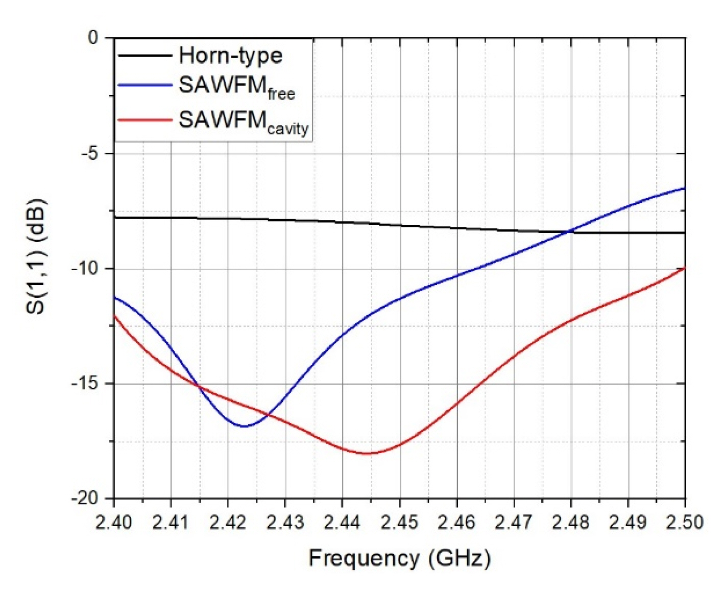
Fig. 9 shows the impedance matching characteristics of the three systems. The reflection coefficient characteristic for S(1,1) is usually required to be lower than −10 dB. The return loss is larger than 10 dB for both designs to satisfy the impedance matching requirement. However, in the case of heating facilities using microwaves, it is better to make the reflection as small as possible (for example, S(1,1) ≤ 13 dB corresponding to less than 5% reflection) for energy-efficient operation. To meet the conditions, an external matching circuit such as a waveguide stub tuner should be additionally attached for the horn type and SAWFMfree. In the case of SAWFMcavity, it is possible to obtain excellent impedance matching characteristics at a center frequency of 2.45 GHz without additional impedance matching circuits. This is because a more accurate impedance matching is possible since the calculation of the normalized admittance value of each slot includes the cavity.
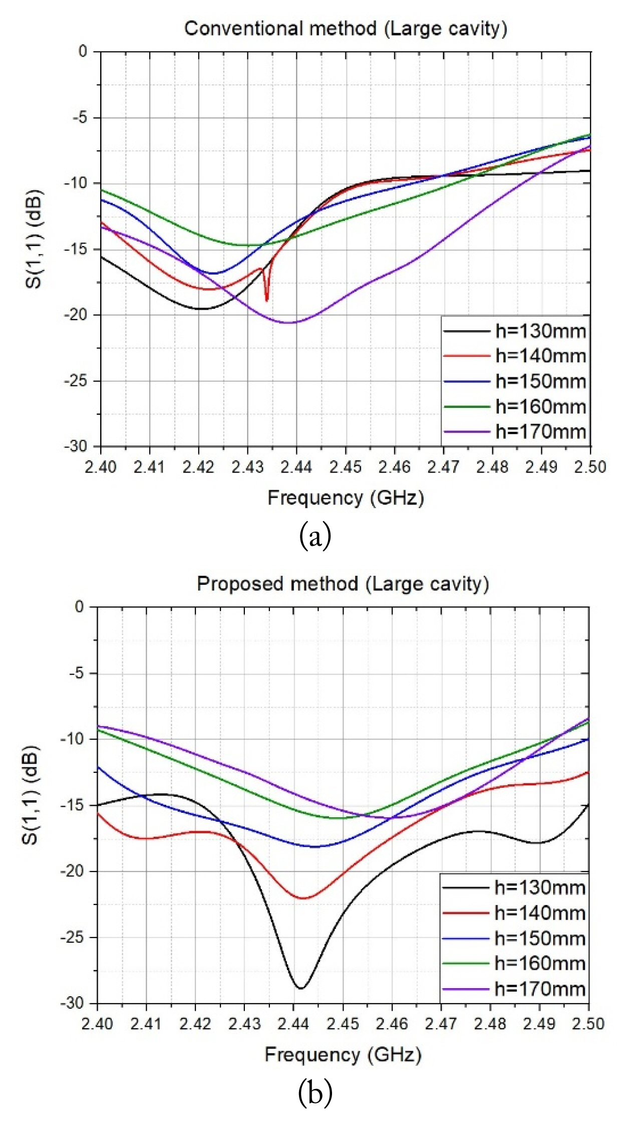
Generally, the resonance-based WSA antenna has very narrow band characteristics. Therefore, when it is used as the feeding structure in an industrial microwave heating facility, it may have characteristics that are very sensitive to internal load changes (e.g., dielectric constant, height, etc.). Even though the impedance matching can be obtained through the external matching circuit, the tuner has to be adjusted whenever the internal condition of the cavity changes.
Fig. 10(a) and (b) show the impedance matching characteristics according to the loading of VOC absorbent for SAWFMfree and SAWFMcavity, respectively. The height of the VOC absorbent material inside the cavity varies from 130 to 170 mm with 10 mm intervals. In both models, the reference dielectric height is 150 mm. In the case of SAWFMfree, it can be seen that the impedance matching characteristic deteriorates to −10 dB depending on the change in dielectric height. However, in the case of SAWFMcavity, it can be seen that the impedance matching characteristic is maintained below −15 dB despite the dielectric height change, and it can be stably operated without manipulating an external matching circuit according to a change of the load in the cavity.
VI. Conclusion
In this study, two types of slotted waveguide array in the frequency of 2.45 GHz are designed to improve the heating uniformity of the quadrangular prismatic microwave cavity used for a VOC removal system. Both follow the equivalent circuit approach of the WSA antenna design. The difference is whether the cavity is included when extracting the impedance data of the slot. Both methods confirm that the heating uniformity is improved by 52% compared with the conventional horn-type excitation case, and the uniformity difference between the two models is below than 1%. However, the model using the impedance data of the slot including the cavity has been found to have better impedance matching by 6.35 dB and shows better load-insensitive characteristics than the model designed by extracting the impedance data of the slot in the free space. As a result, the impedance value of the slot should be extracted taking the cavity effect into account for the design of the slotted waveguide feeding structure that improves the reflection and load-insensitive characteristics while improving the heating uniformity compared with the horn-type feeding structure.