I. Introduction
Currently, wireless power transfer (WPT) technology is being studied and used for various applications, including low-power mobile phones and high-power wireless charging systems, such as those used for drones and electric vehicles (EVs) [1]. Since this technology can solve the problems of limited battery storage, it is expected to be useful for various purposes in the future.
However, WPT systems cause electromagnetic field (EMF) leakage in their vicinities. This leakage can adversely affect nearby human bodies; therefore, to ensure the minimum safe human exposure to EMF leakage from such systems, international guidelines and standards recommend that the leakage should meet reference levels [2–4].
To reduce EMF leakage from WPT systems, different types of shielding methods have been investigated, which can be divided into passive, reactive, and active shielding categories [5]. Passive shielding methods use metal or magnetic materials to guide or block the leakage of magnetic fields, but metal shielding results in a significant reduction in power transfer efficiency (PTE). Also, magnetic materials have low shielding performance (SP). For reactive shielding methods, transmitting (TX) and receiving (RX) coils cause induced current to flow through the shielding (SH) coil to generate a counteracting magnetic field. Lastly, active shielding methods intentionally generate canceling EMFs with the desired magnitude and phase. Under these operating conditions, active shielding methods have a higher SP than reactive shielding methods [6].
Active shielding systems can be divided into two types: one using a dependent power source and the other using an independent power source [6–8]. The active shielding method using a dependent power source generates a canceling magnetic field because the TX and RX coil windings turn in opposite directions. Opposite-direction winding has negative mutual inductance for forward-direction winding, so the effective inductances of the TX and RX coils decrease. This can be a drawback that significantly reduces the PTE of the system. Also, the PTE decreases when the opposite-direction winding increases for high SP. To overcome this limitation, studies have proposed an active shielding system using an independent power source [6, 8]. The active shielding system operates independently of the WPT system; thus, it can achieve high SP by controlling the current strength and phase of the SH coil.
The active shielding methods in previous works have been studied for high SP in an aligned state, but they have not considered misalignment conditions. A WPT system may not always transmit power in perfect alignment due to the movement of the transceiver [9–11]. In this case, the SP decreases due to changes in the magnetic field generation characteristics. Consequently, human exposure to EMFs can increase due to decreased SP under misalignment conditions [12], necessitating the development of an active shielding control method that uses an independent power source under misalignment conditions.
This paper proposes a control method for an active shielding system using an independent power source under misalignment conditions. The active shielding system is controlled by reflecting the current strength and phase of the WPT system under misalignment conditions, and the proposed method was analyzed and verified using simulations and experiments. The organization of this paper is as follows: Section II presents the misalignment condition analysis, Section III explains the verification based on the simulations and experiments, and Section IV presents the conclusions.
II. Misalignment Condition Analysis
1. Mutual Inductance Analysis
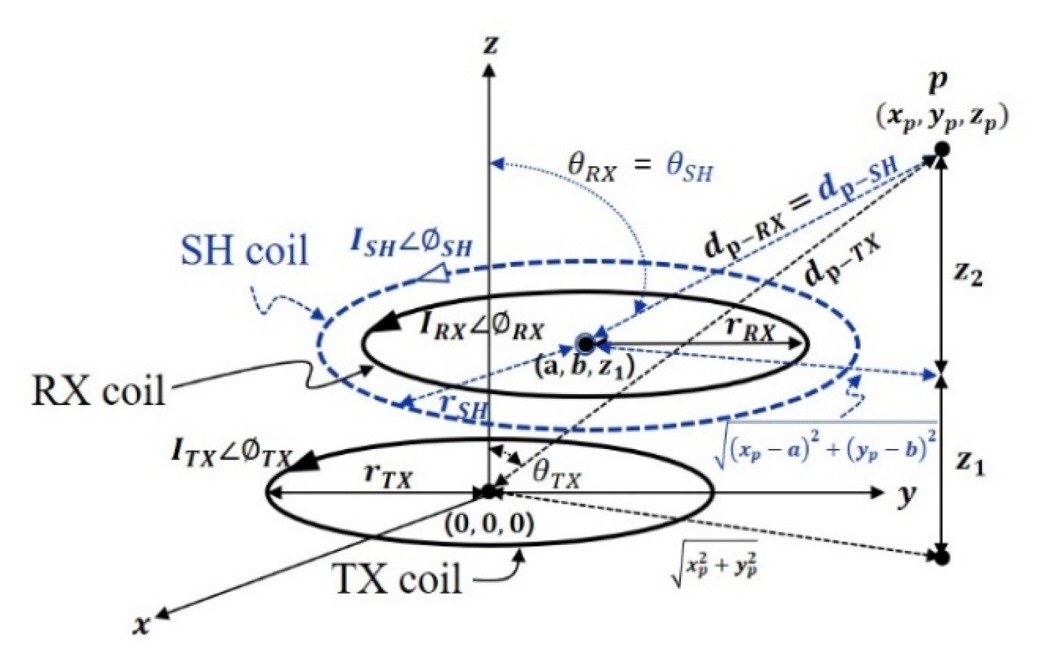
Fig. 1 shows the geometry of the TX, RX, and SH coils under misalignment conditions. I, φ, and r refer to the current, phase, and radius of the coil, respectively. A misalignment condition is set for RX and SH coils, which moves in the x and y directions, increasing the distance from the TX coil. The RX and SH coils are located at a position moved by a and b on the x and y axes of the Cartesian coordinate. dp-TX, dp-RX, dp-SH are the distances from the center of the TX, RX, and SH coils to point p (xp, yp, zp), calculated by Eqs. (1) and (2). The angles between the z axes are expressed as θTX, θRX, and θSH. The magnetic field strength from each coil at point p can be calculated by Eq. (3), where ϑ = sin θ cosϕ cos θ [6].
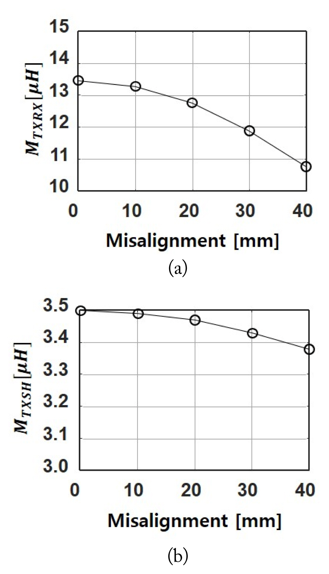
Fig. 2 shows the mutual inductance (M) variations of the RX and SH coils from the TX coil due to misalignments. MTXRX is the M between the TX and RX coils, and MTXSH is the M between the TX and SH coils. The TX and RX coils have identical radii of 95 mm, and the SH coil radius is 150 mm. The air gap between the TX and RX coils is 75 mm. The displacement of the RX and SH coils ranges from 0 to 40 mm in 10 mm steps on the x axis.
Although the RX and SH coils have identical displacements, the variations of MTXRX and MTXSH differ because of the radius difference between the RX and SH coils.
M is determined by geometry, including the radius and distance of each coil. M between two coils is calculated using the Neumann formula according to Eq. (4) [13]. g is a distance between two coils, and M can be expressed in terms of the coupling coefficient (k) and the inductances of two coils determined by Eq. (5).
M between two coils decreases as misalignment occurs in the WPT system. In other words, the operation characteristics of the WPT system change under misalignment conditions due to M variations; therefore, this M variation should be considered to control the active shield system for high SP.
2. Power Transfer Efficiency Analysis
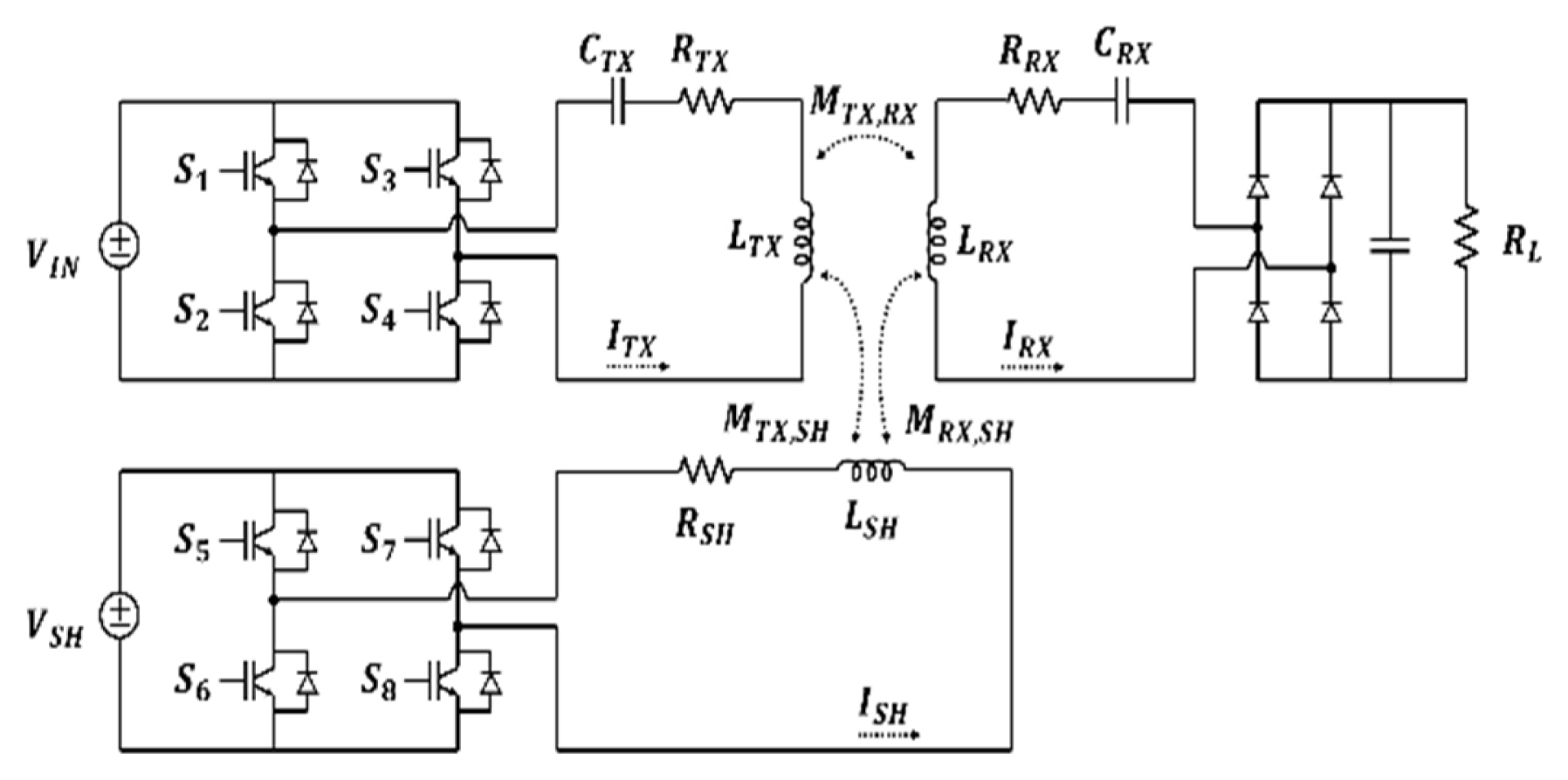
Fig. 3 shows the equivalent circuit of the WPT system, including the independent active shielding system. VIN and VSH are the voltage sources of the TX and SH system; S1–S8 are the MOSFETs for full-bridge inverters of TX and SH; and ITX, IRX, and ISH are the currents of the TX, RX, and SH coils.
The TX and RX systems comprise inductance L, capacitance C, and resistance R, respectively; RL is the load resistance. The SH system is composed of inductance and resistance without a resonant capacitor.
Based on Kirchhoff’s voltage law (KVL), the impedance of the circuit can be expressed by Eqs. (6)–(8). The impedance changes according to KVL because the M changes under misalignment conditions; consequently, the voltage and current characteristics can also vary.
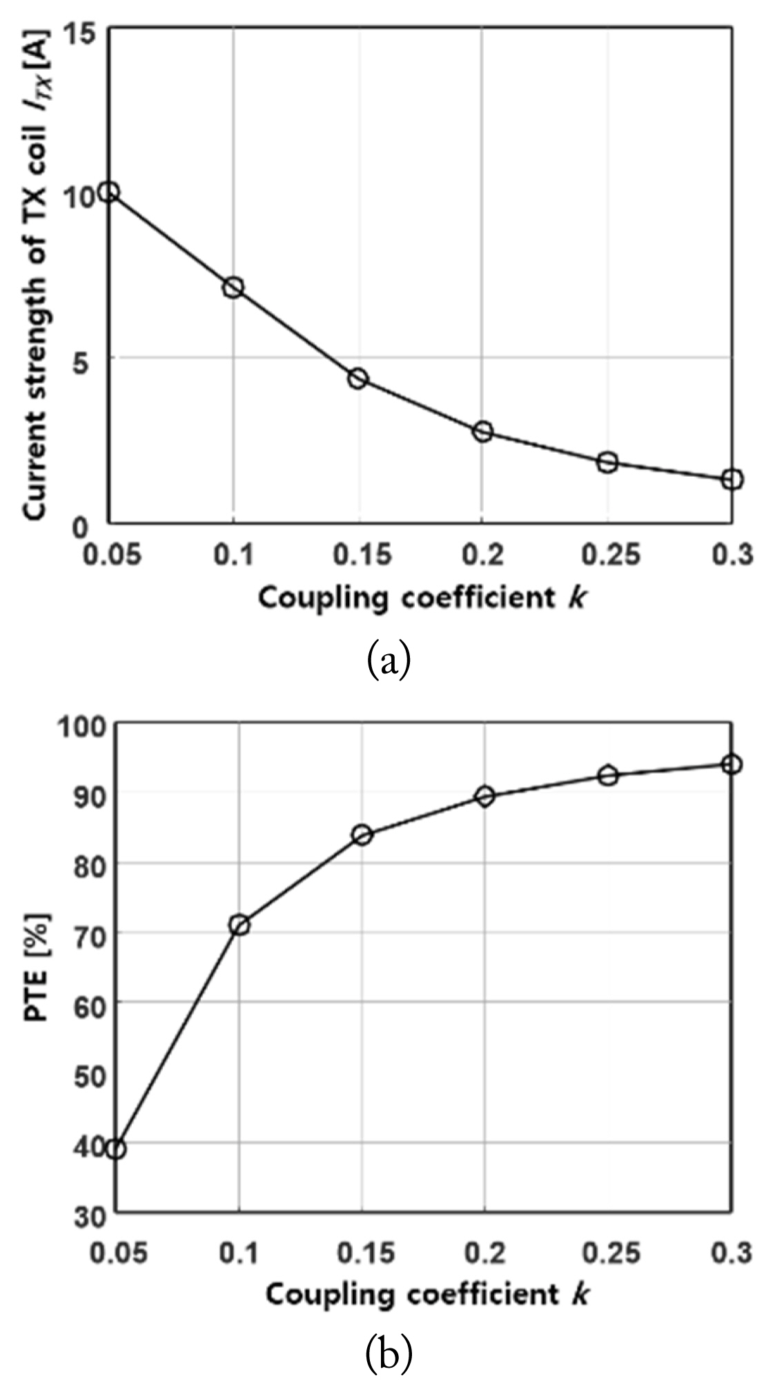
Fig. 4 shows the current strengths and PTE variations according to k under identical load power (PLoad). The TX and RX coils have identical 150 mm radii, and the current strength of the TX coil is calculated while changing k from 0.05 to 0.3.
Fig. 4(a) shows the variation in ITX according to the k variation. The more k decreases, the more ITX increases, meaning that power loss increases in terms of ohm loss I2R under misalignment conditions. Furthermore, the required ISH should be increased for high SP because of the increased ITX, resulting in increased power loss in the SH system.
Fig. 4(b) shows the variations in the PTE of the system according to k variation. The decrease in k results in a decrease in the PTE. Decreasing k due to misalignment reduces the impedance of the circuit and changes the characteristics of the system to low voltage and high current. The high current characteristic has the effect of increasing the power loss at the coil.
Also, when the SH coil is applied to the WPT system, MTXSH and MRXSH should be considered. The magnetic field of the SH coil is out of phase with that of the TX and RX coils, which causes a decrease in the effective inductance of the TX and RX coils, as shown by Eq. (9). Consequently, the PTE decreases when applying the SH system. The PTE of the WPT system, including the active shielding system using an independent power source, can be calculated using Eq. (10).
3. Current and Phase Control of the Shielding System
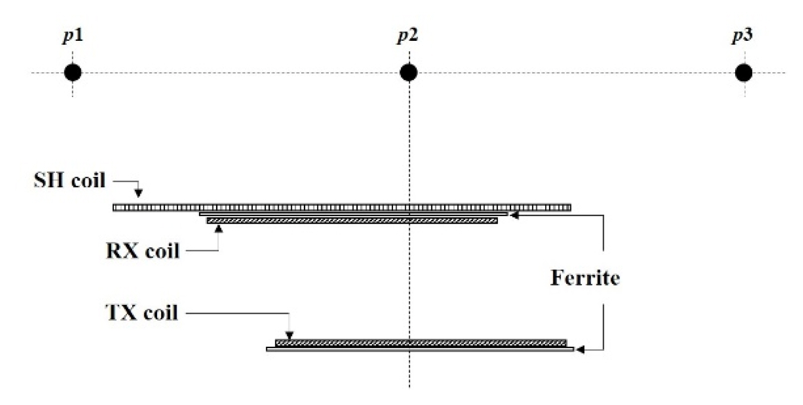
Fig. 5 shows the front view of the WPT system, including the SH coil. To achieve high SP, the current applied to the SH coil should be determined, considering misalignment conditions. However, since the positions and designs of the three coils of TX, RX, and SH differ, the composite magnetic field in space varies depending on the positions, meaning that the shielding current and phase of the shielding coil depend on the target point p.
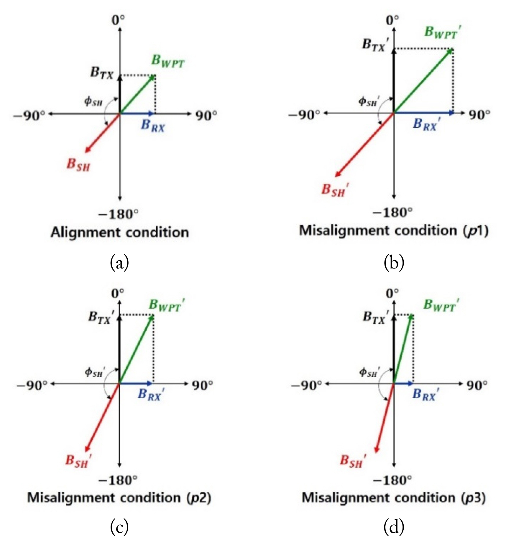
Fig. 6(a) shows a magnetic vector diagram of the TX, RX, and SH coils in the alignment condition. The magnitude and phase of BWPT is calculated by Eqs. (11) and (12) [6]. The maximum SP is obtained when the SH coil has an identical magnetic field strength and 180° of phase difference for the BWPT; however, the magnetic field strengths of the TX and RX coils change under misalignment conditions.
Fig. 6(b)–6(d) show the magnetic flux density and phase changes according to the measurement point p under misalignment conditions. BTX′, BRX′, and BWPT′ are the changed magnetic flux densities under misalignment conditions. The BTX′ defined in Eq. (3) increases according to increased ITX′, which is the TX coil current under misalignment conditions. ITX′ increases by decreasing MTXRX under misalignment conditions, as described in Section II-2. BRX′ differs significantly depending on p because, although IRX′ is identical to IRX, the distance to point p differs. Compared to the alignment condition, BRX′ increases at p1, is equal at p2, and decreases at p3.
According to Eq. (12), the changes in Bp-TX and Bp-RX cause a change in Φp–PWT. As the change occurs from p1 to p3, the distance from the RX coil increases; thus, Bp-RX decreases and Bp-TX becomes dominant. In this case, the φp–SH approaches the opposite direction of φp–TX as it goes from Fig. 6(b) to 6(d). Therefore, BSH′ must be controlled according to the target point p and BWPT′ to achieve high SP.
Assuming that the RX and SH coils are located at a point (a, b, z1), as shown in Fig. 1, the distance between the TX and SH coils, g′, is calculated using Eq. (13). MTXRX′ can then be calculated using Eq. (4) by substituting the distance g to g′. Since an identical PLoad is assumed, VRX′ and IRX′ are identical under the alignment condition, and ITX′ can be calculated through MTXRX according to Eq. (14). Thus, using the calculated ITX′ and the known IRX′, the magnetic field strengths BTX′ and BRX′ at point p can be calculated using Eq. (3). As a result, the magnitude and phase of the ISH′ is determined based on the BSH′ according to Eqs. (11) and (12).
III. Simulation and Experiments
1. Simulation and Experimental Setup
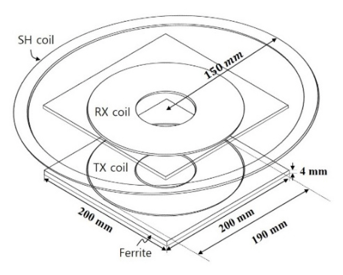
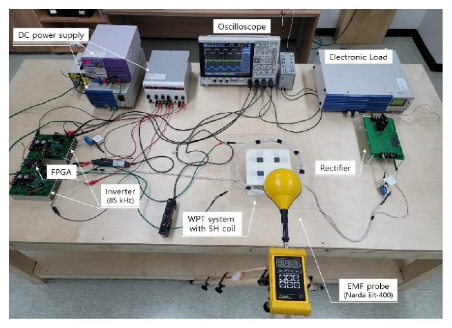
Fig. 7 shows the simulation and experimental model, and Fig. 8 shows the experimental setup. Also, Table 1 shows the electrical parameters of the WPT and SH coils, and PLoad and PTE before and after applying the SH coil. The TX and RX coils had outer and inner radii of 95 mm and 35 mm, respectively; the diameter of the wire was 4 mm. Ferrite plates with widths and lengths of 200 mm × 200 mm and heights of 4 mm were used for the TX and RX coils. The radius of the SH coil rSH was 150 mm, and the number of turns was set to five. The operating frequency of the WPT system was 85 kHz, and RL was 10.016 Ω. Also, the input voltage was adjusted to an identical PLoad of about 100 W for all measurements.
Fig. 9 shows the alignment and misalignment conditions considered in the simulations and experiments: alignment, which is the condition in which the RX and SH coils are aligned on the z axis with the TX coil; and misalignment, meaning that the RX and SH coils are misaligned by 40 mm in both the x- and y-axis directions.
Fig. 10 shows the measurement points (MPs) used to analyze SP. The MPs were set as the center and periphery of the system from MP1 to MP9 at distances of 15 cm above the RX coil.
The results according to the alignment and misalignment conditions were as follows: as misalignment occurred, ITX increased. Regardless of the alignment condition, the PLoad was identical, so the IRX did not change. However, when controlling for the misalignment condition, the ISH increased, and the ΦSH shifted close to the opposite direction of the TX, which was closer to −180°.
Table 2 shows the current strengths and phases of the TX, RX, and SH coils under alignment and misalignment conditions. For the misalignment conditions, the current strengths and phases were controlled. The shielding system control set the target point p as the center point of the alignment condition to evenly reduce all high magnetic fields at close ranges around the system.
2. Simulation and Experimental Results
Fig. 11 shows the results of the simulations and experiments for the leakage magnetic field strength under alignment and misalignment conditions at nine different MPs when the SH coil was not applied. The magnetic field leakage increased when misalignment occurred. Under misalignment conditions, the leakage magnetic field strength around the locations where the RX coil was positioned (MPs 4, 5, 7, and 8) increased because the ITX had increased for transferring identical PLoad against a decrease of MTXRX.
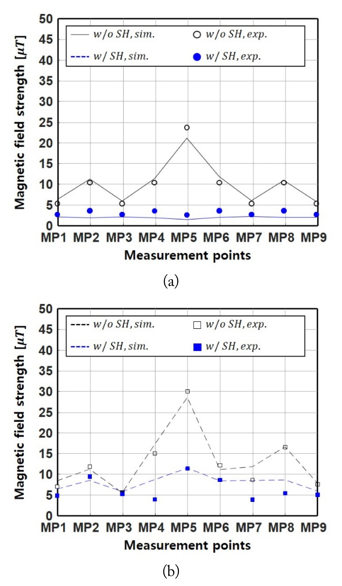
Fig. 12(a) shows the simulation and experimental results for EMFs for the SH system under alignment conditions. The EMFs at all MPs decreased when the SH system was applied. In particular, since point p was selected as the center point for the alignment condition, the highest EMF reduction occurred at MP5, as shown in Fig. 12(a). The SP was calculated according to Eq. (15), and the average SP was the sum of the SPs from MP1–MP9 divided by 9. BwoSH and BSH were the leakage magnetic field strengths before and after the application of the SH coil. The average SP under the alignment condition was 67.16%.
Fig. 12(b) shows the simulation and experimental results for EMFs according to the SH system under misalignment conditions. Although EMF leakage decreased under misalignment conditions, the average SP was 49.22%—inferior to the alignment condition—because the current amplitude and phase of the SH coil were determined based on the alignment condition.
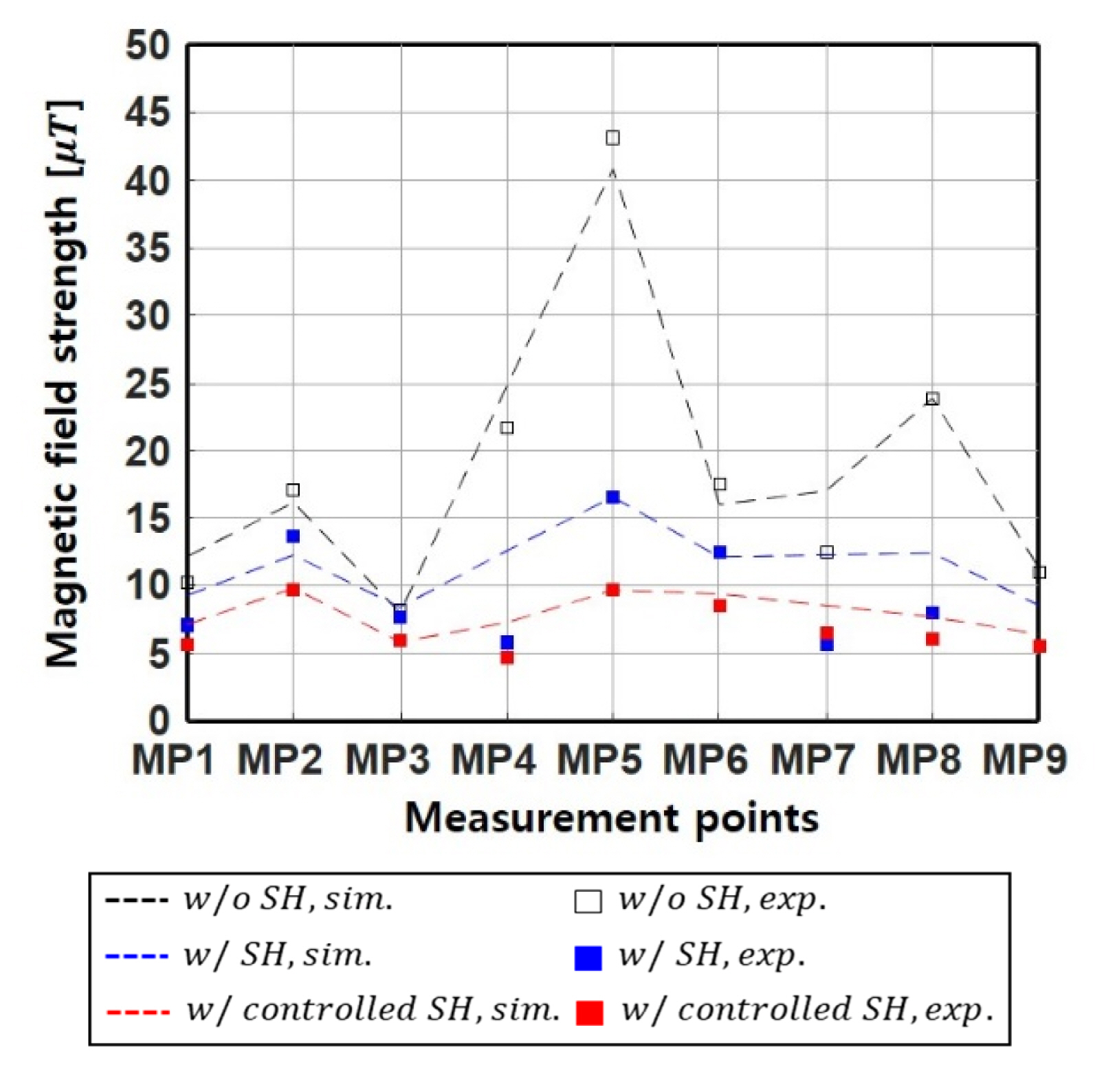
Fig. 13 shows the SP variations according to the active shielding control when misalignment occurred. The SP was improved by adding active shielding control under misalignment conditions. We confirmed that this improvement in SP occurred in all MPs, as well as at the target shielding point. The average SP of the controlled SH coil was 61.74%.
Consequently, the average SP under misalignment conditions was increased from 49.22% to 61.74% by applying the proposed control method. This meant that 24.6% of the EMF leakage was additionally reduced by applying active shielding control for misalignment conditions.
Table 3 shows the PTE variations under misalignment conditions. Pin is the sum of the supplied power for TX and SH. The power transfer conditions for all measurements were 100 W transmission to RL. As shown in Table 3, the proposed active shielding control method produced no additional PTE degradation, meaning that the SP could be improved without PTE degradation under misalignment conditions.
IV. Conclusion
This paper proposes a control method for an independent active shielding system under misalignment conditions. Changes in the operating characteristics of WPT systems, such as M and ITX, according to the misalignment, were reflected in the shielding current control determination. Based on this, we propose a method for determining the current strength and phase of the shielding coil under misalignment conditions. When the proposed method was applied, the experimental results showed that the SP improved from 49.22% to 61.73% under misalignment conditions. Also, no further PTE reduction occurred when we applied the proposed control method. In conclusion, we verified that SP could be improved for misalignment conditions by applying independent active shielding.