Compact Bent-Corner Orthogonal Beam Switching Antenna Module for 5G Mobile Devices
Article information
Abstract
Typically, users engage with smartphones in either single-hand or dual-hand mode. To design antennas that operate at 28 GHz and have high pattern integrity for both modes of operation, an orthogonal beam switching module is required as a single phased-arrays would fail. First, a corner bent corporate fed array operating at 28 GHz is proposed, which has a forward gain of 8.5 dBi and a high-front-to-back ratio of 20 dB. Second, a corner bent printed Yagi antenna that also operates in the 28 GHz band is proposed. Both the corner bent antennas are compatible with the panel edge of commercial smartphones. The radiation from both antennas is mostly directed away from the user. A corner bent co-polarized orthogonal beam switching module is presented and characterized. The antenna module also has a shared ground, making it a potential candidate for future 5G smartphones. Detailed results are presented with adequate justification.
I. Introduction
Several recent reports strongly suggest that data consumption on mobile devices will see a surge in the coming years. Current commercial deployment of cellular systems may not be able to handle this demand [1]. Researchers opine that shifting the carrier frequencies to millimeter wave frequencies might be a feasible solution. Several variants of testing campaigns have testified the feasibility of millimeter waves as carrier frequencies for outdoor communication links [2, 3]. It is hard to design communication links because of the high free-space path loss and high penetration loss [1]. Free-space path loss could be mitigated by increasing the gains of the antennas on the base station and the mobile device, respectively. The gain of the antenna is dictated by the physical aperture of the antenna [4]. Researchers [3, 4] argue that if the carrier frequency were shifted to millimeter waves, the antenna size would automatically shrink, and increasing the number of elements would enhance gain for the same physical footprint [3].
Commercial smartphones have very limited space for antenna integration [5]. If smartphones have to be compliant with the market standards, then the available space for antennas would be 10 cm × 5 cm × 0.7 cm on average. It would be a challenge to accommodate 5G antennas with 4G antennas to support backward compatibility in this restricted space on a mobile device [6–8]. Several topologies for 5G smartphones have been reported in recent years [9–22]. Only a few antenna designs operating in the 28 GHz band are compliant with commercial smartphone dimensions [6, 8, 9, 13] but these designs are not corner bent.
Users usually engage with the mobile device in one of the two modes, namely single-hand or portrait mode and dual-hand or landscape mode, as shown in Fig. 1.
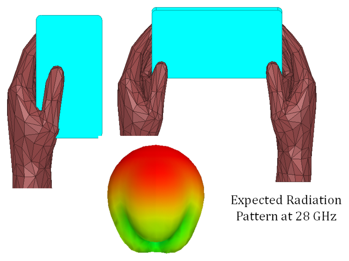
Schematics for single-hand and dual-hand modes.
The antennas to be integrated with the panel of the device must have orthogonal beam switching capability with minimal physical footprint and radiation being primarily away from the user.
The current de-facto standard for designing antennas for mobile devices has been phased arrays for 5G antenna systems [3]. The beam scanning of a 4-element phased array of patch antennas is illustrated in Fig. 2. The 3D patterns prove that a typical phased array system would suffer from scanning loss up to 3 dB if the beam were formed at 45°; beyond this angular scan, the patterns become unusable, as observed in [10, 11, 13–17]. If the beam integrity were compromised, the phased array would fail to operate when excited for orthogonal beams, which is a requirement for the use case in consideration, as per Fig. 1. Several pattern-diversity schemes have been proposed [23–31], but these schemes would be in-operational for orthogonal beams or would not necessarily fit compactly in a commercial smartphone. Hence, a corner bent shared ground orthogonal beam switching module is presented.
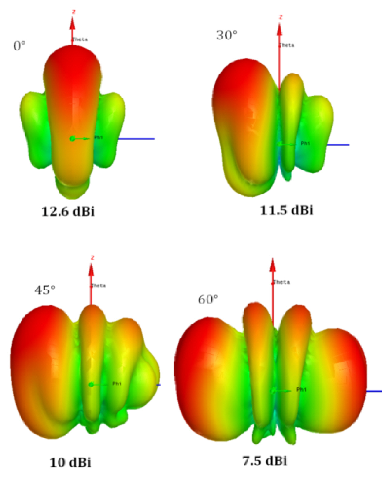
Scanning loss demonstration of a 4-element array.
II. Corner Bent Array
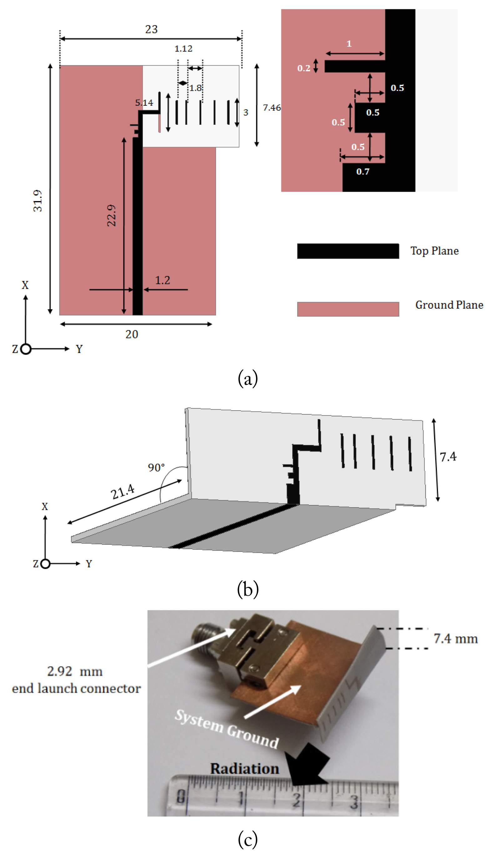
Planar broadside antennas, when integrated with the mobile device would radiate toward the user, leading to a noticeable amount of attenuation due to human tissue [11, 13, 15]. On the other hand, a planar end-fire antenna, such as a printed dipole or printed Yagi antenna [10, 12, 23, 29–34] would have a high front-to-back ratio and radiate most of the energy toward the base station. However, both types of antennas would have a significantly large footprint, as the space near the transmission lines would be unusable [35–40]. Hence, a corner bent unidirectional antenna design is proposed in this section. As there are two modes of smartphone operation, the antennas corresponding to both modes are independently designed and integrated together with a shared ground. First, a single-hand mode is designed. A corner bent corporate fed array is proposed. The planar version of the antenna is illustrated in Fig. 3(a). The antenna is designed on a Nelco NY9220 substrate with a dielectric constant in the range 2.18 to 2.22 and a dielectric loss tangent of 0.0009. Ideally, for high radiation efficiency, air should be used as the substrate, but designing metallic radiators floating in air would not be feasible [4]. Also, coaxial feeding is avoided to aid in conformity. The proposed antenna is constructed on a 20-mil substrate, which is a compromise between flexibility and impedance bandwidth [4]. The feed is a 50-Ω transmission line, which is matched to the impedance of the inset fed patch antenna through a 1 × 4 power divider.
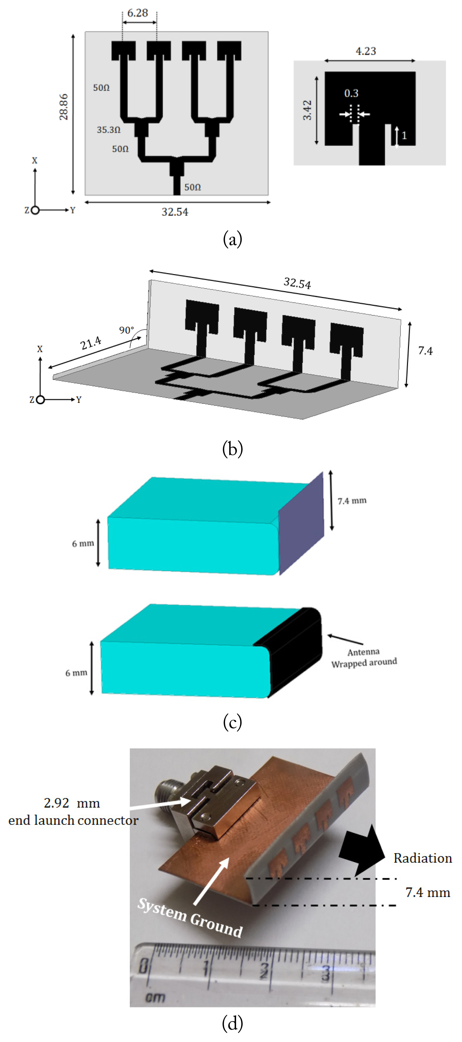
(a) Corporate fed planar array (unit: mm). (b) Corner bent array (unit: mm). (c) Concept of wrapping. (d) Photograph of the prototype.
The proposed antenna, when integrated with the panel of the mobile device, would not be practical to implement. Hence, a corner bent version of the same is investigated, Fig. 3(b). It is well known that the slots from the fringing fields create radiation from a patch antenna; hence, the effective radiating area is decided by the inset fed patch alone. This could be in the orthogonal plane (XY plane), and the transmission line along with the power divider network could be built in the YZ plane, thus reducing additional radiation arising due to discontinuities in the feeding network. As evident from Fig. 3(b), the radiators are compatible with the smartphone panel height. The corner bent design could be further extended to a wrapped-around version, as illustrated in Fig. 3(c). The corner bent antenna could be conformed onto the curved panel of typical smartphones. As the actual radiating aperture of the antenna is unharmed post conforming, the proposed antenna would deliver the desired characteristics. The fabricated prototype is shown in Fig. 3(d), and a 2.92 mm southwest end-launch connector is used for measurements. The radiators are placed at least 1λ away from the feed plane, which ensures minimal influence of the electrically large connector on the measurements.
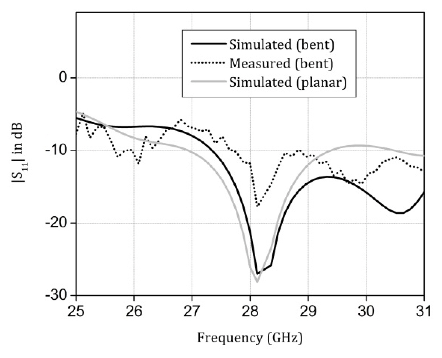
This concept of conformal array could even be designed with an aperture-coupled feeding technique. The input reflection coefficient is shown in Fig. 4. It is evident from the curves that the variation between the planar and corner bent versions of the proposed elements is minimal, as the bending happens mostly on the transmission line feeding the radiators, and not necessarily on the ground plane. The simulated impedance bandwidth is from 26 to 29 GHz, translating to 11%. The S-parameter measurement is done with Agilent PNA E3864C. All the simulations were done using Ansys High Frequency Simulation Software (HFSS). The deviation between simulated and measured curves is attributed to a lack of soldering between the end-launch connector and the antenna element. The actual connector used for measurement had undergone numerous mating cycles, leading to deterioration in the connector to antenna transition.
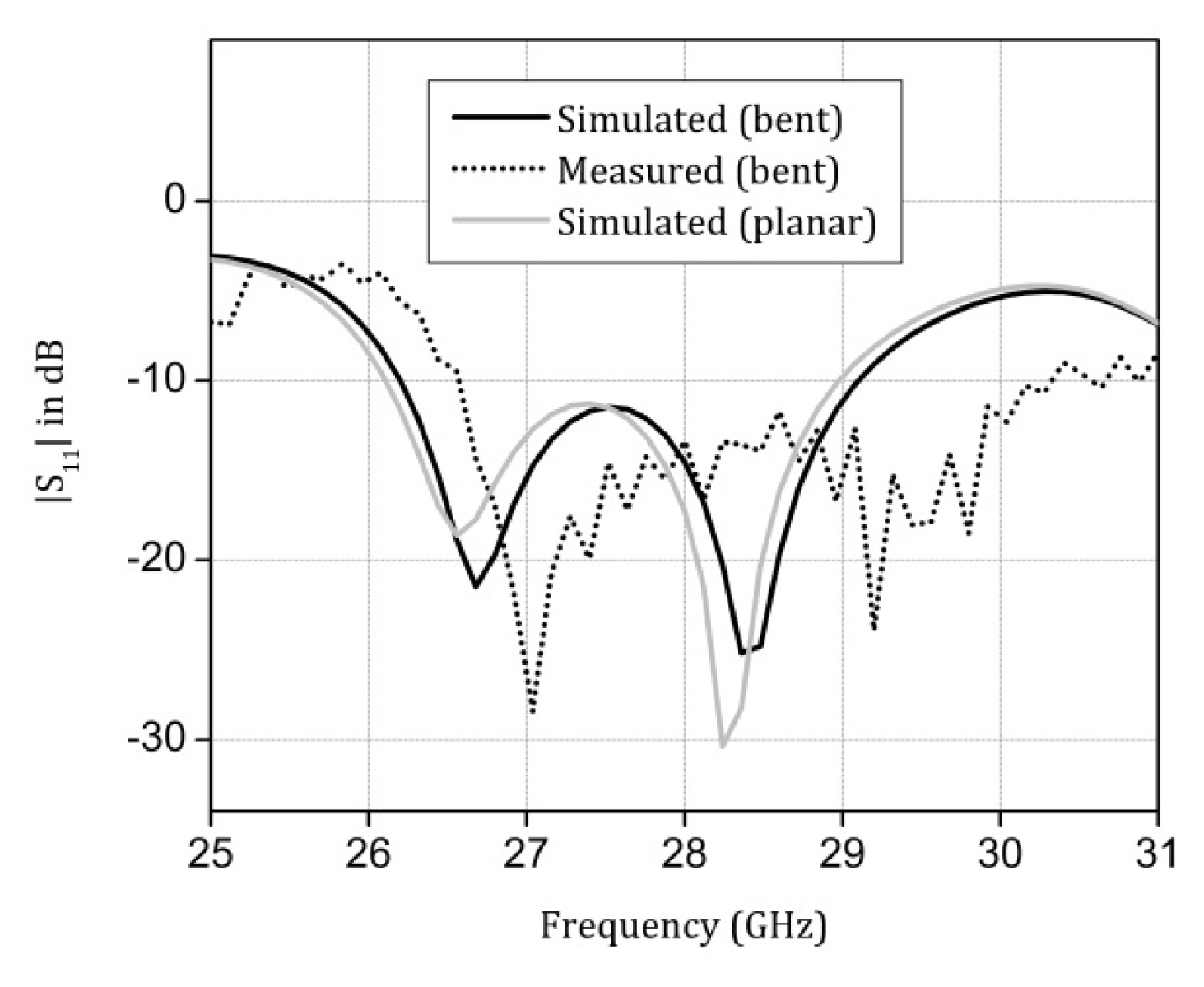
|S11| of the conformal array and its planar counterpart.
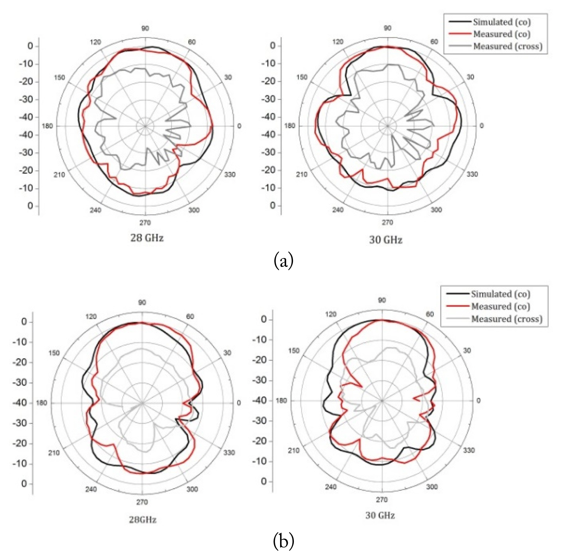
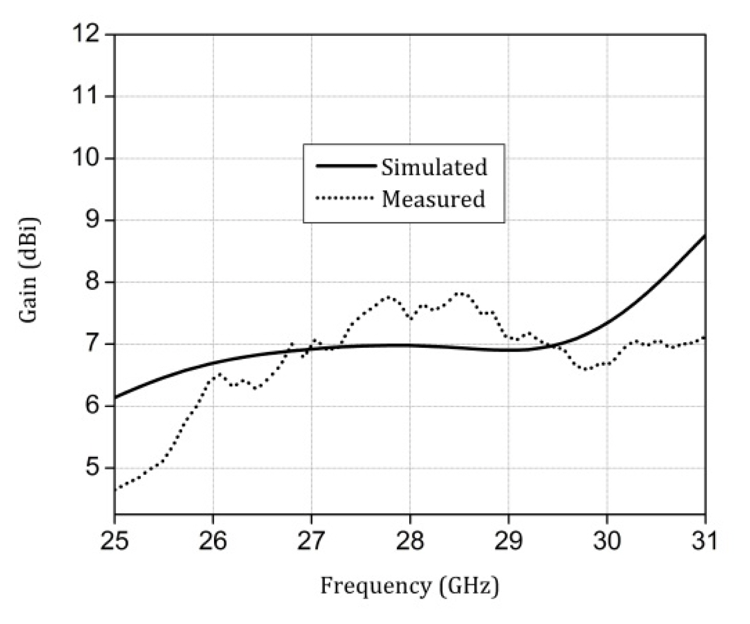
The H-plane or YZ plane patterns are shown in Fig. 5(a), and the narrow beam indicates beamforming along the Y axis. E-plane or XZ plane patterns are illustrated in Fig. 5(b); the wider beam is due to the topology of the array elements. All the radiation patterns were measured in a Ka-band far-field anechoic chamber, as shown in Fig. 5(c). The patterns at 28 and 30 GHz are almost similar, indicating beam integrity across the operational spectrum. The front-to-back ratio is more than 20 dB, which means that the power radiated towards the user’s hand or the user’s body is minimal, and most of the radiated power is directed toward a base station or access point. The cross-polarization level is less than 25 dB, indicating a high polarization purity of the vertically polarized radiating element. The forward gain of the corner bent antenna is depicted in Fig. 6. The simulated value of gain is close to 7.2 dBi at 28.3 GHz with a measured value of 5.8 dBi; the gain could have been up to 2 dB higher if a Wilkinson-based power divider had been used to design the power divider network. The standard gain transfer method was used for gain measurement in an anechoic chamber.
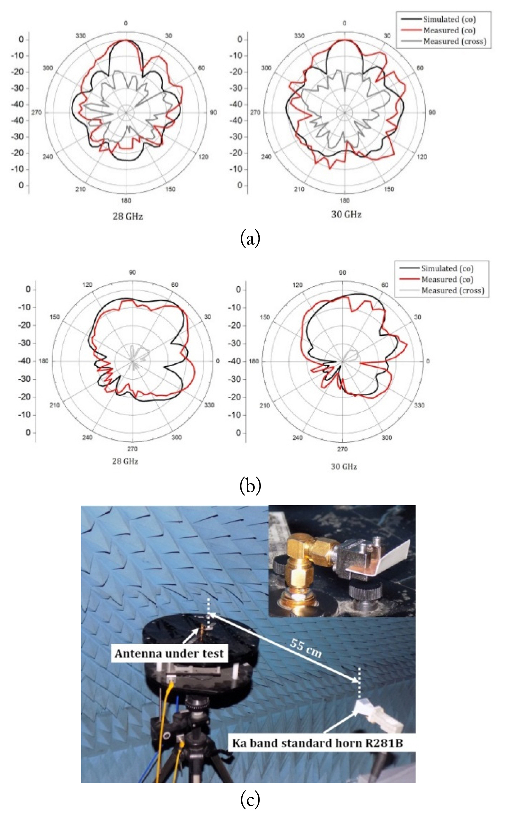
Radiation patterns of the corner bent array: (a) H-plane (YZ plane), (b) E-plane (XZ plane), and (c) experimental setup for radiation pattern measurement.
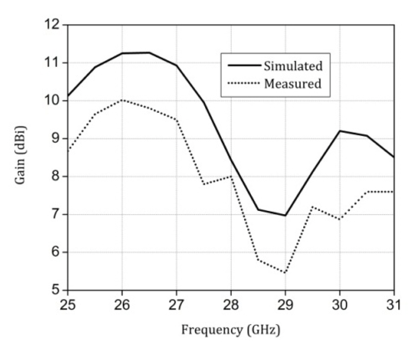
Forward gain of the corner bent array.
III. Corner Bent Printed Yagi
In order to design an antenna that works for the dual-hand mode of Fig. 1, the antenna must radiate orthogonally with respect to the beam of the corner bent antenna presented in section II. The simplest way to realize this is to design either a printed dipole [14] or a planar Vivaldi [12]. The issue with these designs is low gain and non-compliance with the smartphone panel height. Hence, a corner bent printed Yagi is proposed. The planar version of the antenna is illustrated with dimensions in Fig. 7(a). The agenda of this design is to feed along the X axis and get the antenna to radiate along the Y axis so that the antenna can be conformed onto the mobile panel. In order to achieve this objective, an orthogonal printed Yagi antenna is designed. The feed is a standard 50-Ω transmission line feeding the arms of the printed dipole, but a 90° bend is required for this design. A straightforward approach would be to design the transmission line with a bend, but this approach would create additional radiation due to the discontinuity.
(a) Printed Yagi antenna with orthogonal beam (unit: mm). (b) Corner bent Yagi antenna (unit: mm). (c) Photograph of the fabricated prototype.
Hence, stubs that double up as impedance transformers are used to solve the issue. The stubs are shown in the inset of Fig. 7(a). The effective radiating aperture is 7.4 mm; hence, it could be easily integrated onto a mobile panel. The corner bent version of the printed Yagi is shown in Fig. 7(b); the bending does not significantly affect the characteristics of the element. The fabricated prototype along with the mounted end-launch connector is shown in Fig. 7(c). The input reflection coefficient of the corner bent Yagi is shown in Fig. 8. The variation between planar Yagi and its corner bent version is also illustrated in Fig. 8. The input impedance is slightly changed at the higher frequency for the corner bent version due to the variation in the impedance at the corner bending, which happens on both planes of the substrate. The corner bent element has an input impedance bandwidth of 27–31 GHz, translating to 13.8%.
|S11| of the corner bent and planar Yagi.
The radiation patterns are shown in Fig. 9. The antenna has a high front-to-back ratio when conformed, indicating that radiation toward the user would be minimal and satisfy the criteria for the use case, as illustrated in Fig. 1. The forward gain is 7 dBi at 28 GHz, as observed in Fig. 10. Gain could be further increased by increasing the number of parasitic radiators or by integrating the aperture with appropriate sub-wavelength metamaterial unit cells.
Radiation patterns of the proposed Yagi antenna: (a) H-plane (YZ plane) and (b) E-plane (XY plane).
Forward gain of corner bent Yagi antenna.
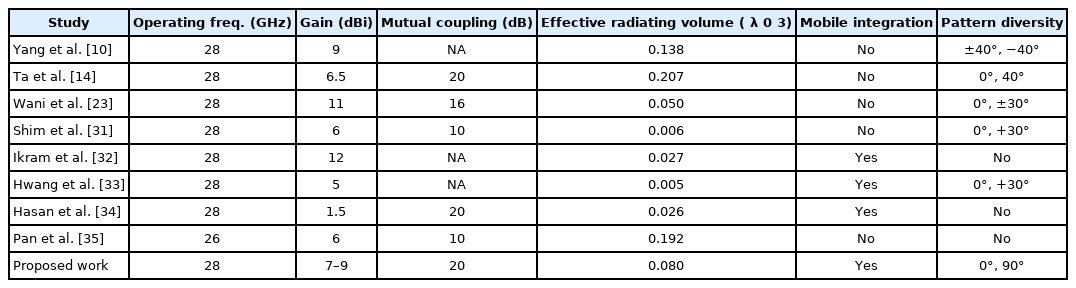
Table 1 proves that the proposed concept of conformity yields high gain for minimal physical footprint compared to other reported articles in the 28 GHz band.

Comparison against reported articles
IV. Shared Ground Beam Switching Module
The proposed antennas of Sections II and III have to be integrated together to be useful as a beam switching or pattern diversity module. The proposed shared ground is illustrated in Fig. 11(a), and the corner bent array and the corner bent printed Yagi antennas are designed on the same ground and conformed together.
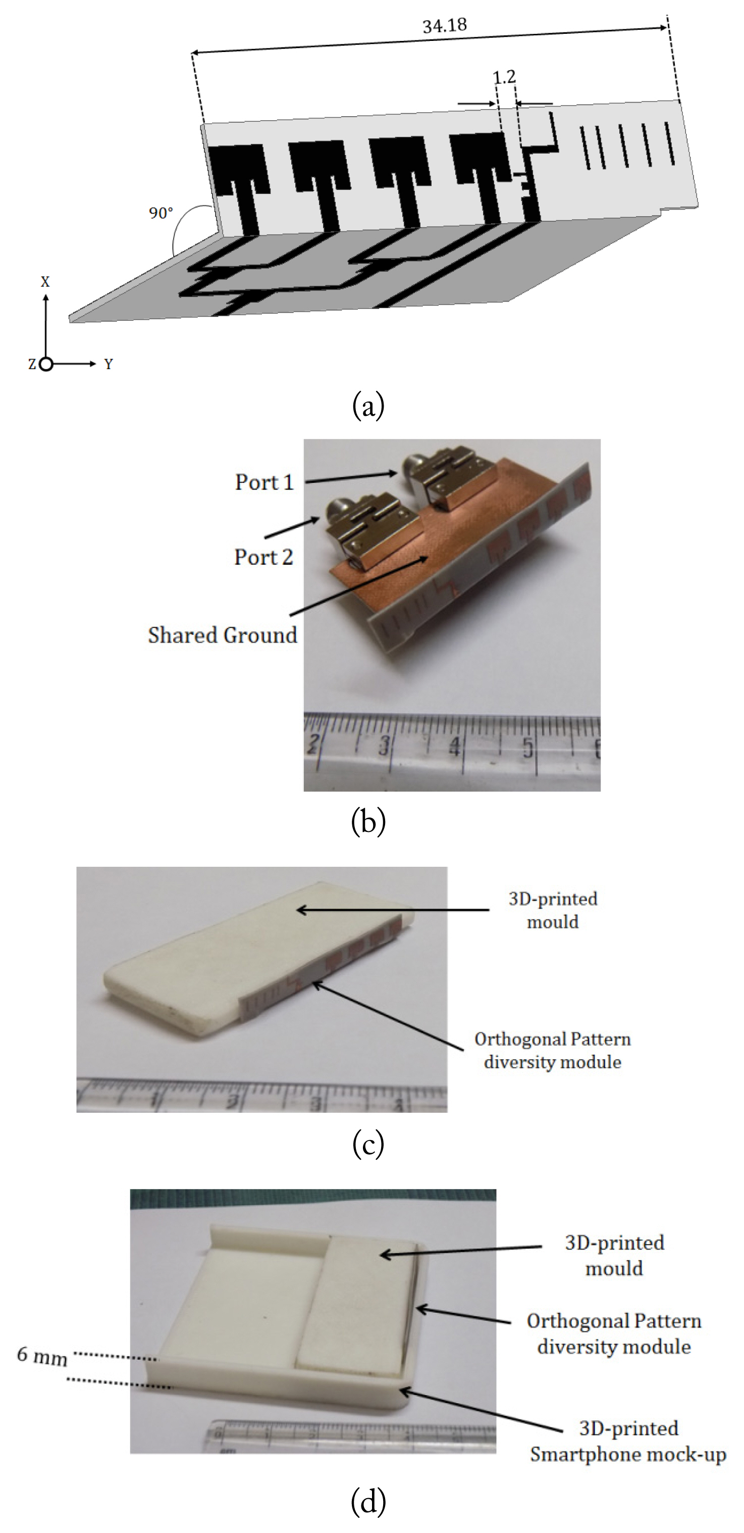
(a) Schematics of the shared ground antenna module (unit: mm). (b) Photograph of the prototype. (c) Prototype with a 3D-printed mold. (d) Prototype with a 3D-printed mock-up.
The array is sliced at the non-radiating edge of the element, which leads to a compact design without altering radiation of the corner bent array. The distance between the two elements is 1.2 mm, which translates to 0.11λ at 28 GHz. It is interesting to note that the orthogonal beam switching module has a shared ground, which means that the RF electronics or the motherboard of the smartphone could be integrated with the module with almost no deterioration in the radiation characteristics of both antenna elements. Designs such as [13] have defected or slotted ground structures, which are usually not recommended by the mobile phone industry. Fig. 11(b) shows the fabricated prototype with the connectors. The distance between the ports was increased to accommodate the bulky connectors.
A 3D-printed mold that mimics a commercial smartphone was designed. The dimensions of the 3D-printed case match those of the commercial mobile device. The fancy curvatures of modern smartphones were also incorporated in the mold design, as evident in Fig. 11(c) and 11(d). The proposed antenna module is mounted to check the compliance of the design, and the module has a minimal footprint that satisfies both modes of mobile device operation. The antennas of the proposed module have vertical polarization similar to industry designs reported or patented in the recent past.
The 3D radiation patterns of the antenna module are depicted at 28 GHz in Fig. 12(a). The patterns are similar to the individual counterparts, indicating a high beam integrity of the antenna module. The specific absorption rate (SAR) at 28 GHz is illustrated in Fig. 12(b), and the intensity of the SAR values within the human head is almost negligible for the proposed topology. In spite of a shared ground and electrical closeness, the simulated value of mutual coupling between the ports is less than 20 dB across the spectrum due to the orthogonal radiation from the respective ports, as shown in Fig. 12(c). The measured value is less than the simulated value of mutual coupling, as the separation between the two ports was increased to accommodate the bulky connectors. Table 2 indicates that the proposed design is electrically compact with mobile panel integration, which has orthogonal beam switching.
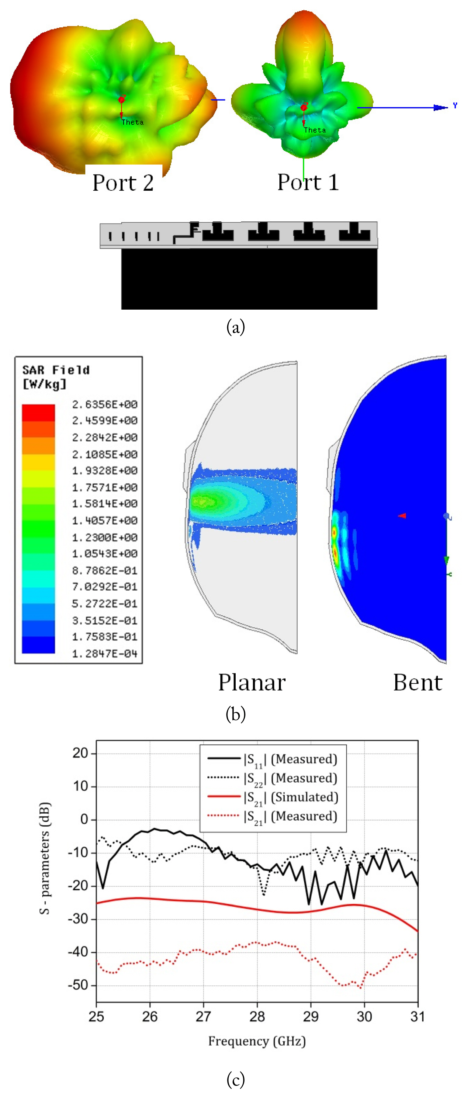
(a) 3D radiation patterns of the module at 28 GHz. (b) SAR graphs for the proposed element at 28 GHz. (c) S-parameters of the proposed module.
Comparison of the module with reported designs
V. Conclusion
In order to achieve the orthogonal beams that will be necessary for the data mode usages of future 5G smartphones, corner bent designs are presented in this article. Phased arrays fail to operate for orthogonal beams; hence, a beam switching module is proposed. First, a corner bent corporate fed array operating in the 28 GHz band is presented, followed by a corner bent printed Yagi antenna. Both the proposed antennas are integrated with a shared ground to achieve orthogonal beam switching with minimal radiation toward the user for both the cases with adequately high gain. Hence, the proposed antenna module could be a candidate for future 5G smartphones.
References
Biography

G. S. Karthikeya is a Member of IEEE, He received his undergraduate degree in electronics and communication engineering, with distinction, in the year 2010 from Visvesvaraya Technological University, Belgaum. He received his Master’s degree, with distinction, in Microwave engineering from University of Kerala in 2012. He worked as an assistant professor in Visvesvaraya technological university from 2013 to 2016, where he es-tablished the Antenna Architects’ lab. He joined Centre for applied Re-search in Electronics, IIT Delhi as a PhD student in 2017 and defended his thesis in 2019. He served as an event secretary of IEEE MTT-S branch at IIT Delhi. He worked as a Project Scientist at Foundation for Innovation and Technology Transfer (FITT) in association with Synergy Microwave Corporation from 2019 to 2021. He serves as the chief coordinator of the Centre for Antennas and Radio Frequency Systems (CARFS), Department of Electronics and Telecommunication Engineering, Ramaiah Institute Of Technology, Bangalore. He has authored or co-authored more than 60 articles in peer-reviewed journals and international conference proceedings. He has also filed 4 Indian patents and 2 US patents. He has co-authored three state of the art books and a book Chapter. He also holds a copyright on 5G antenna module design. One of his articles was featured as a cover feature in Microwave Journal. His research interests include metamaterials, EBG structures, mmWave antennas for mobile terminals and base stations. He is a member of IEEE-Antenna Propagation Society and Antenna Test and Measurement society. He serves as the reviewer of several IEEE and John Wiley journals.

Shiban K. Koul is a Life Fellow of IEEE. He received his B.E. degree in electrical engineering from Regional Engineering College, Srinagar, and his M.Tech. and Ph.D. degrees in microwave engineering from the Indian Institute of Technology Delhi. He has been an Emeritus Professor with the Indian Institute of Technology, Delhi since 2019. He served as Deputy Director (Strategy and Planning) with IIT Delhi from 2012–2016 and IIT Jammu from 2018–2020. He also served as the Chairman of Astra Microwave Products Limited, Hyderabad, from 2009–2019. He has authored or co-authored 513 research articles, 15 state-of-the-art books, 4 book chapters, and 2 e-books. He holds 22 patents, 6 copyrights, and one trademark. He has guided 26 Ph.D. theses and more than 100 master’s theses. His research interests include the following: RF MEMS, high frequency wireless communication, microwave engineering, microwave passive and active circuits, device modelling, millimeter and sub-millimeter wave IC design, body area networks, flexible and wearable electronics, and reconfigurable microwave circuits, including miniaturized antennas. He is the Chief Editor of the IETE Journal of Research, Associate Editor of the International Journal of Microwave and Wireless Technologies, Cambridge University Press. He served as a Distinguished Microwave Lecturer at IEEE MTT-S for the period 2012–2014. He is the recipient of numerous awards, including the IEEE MTT Society Distinguished Educator Award (2014); the Teaching Excellence Award (2012) from IIT Delhi; the Indian National Science Academy (INSA) Young Scientist Award (1986); the Top Invention Award (1991) of the National Research Development Council for his contributions to the indigenous development of ferrite phase shifter technology; the VASVIK Award (1994) for the development of Ka-band components and phase shifters; the Ram Lal Wadhwa Gold Medal (1995) from the Institution of Electronics and Communication Engineers (IETE); the Academic Excellence Award (1998) from the Indian Government for his pioneering contributions to phase control modules for Rajendra Radar; the Shri Om Prakash Bhasin Award (2009) in the field of Electronics and Information Technology; the VASVIK Award (2012) for contributions made to the area of Information Communication Technology (ICT); and, finally, the M N Saha Memorial Award (2013) from IETE.

Ajay K. Poddar is an IEEE Fellow, and he graduated in Electronics & Communication Engineering from the National Institute of Technology Calicut, India. He has a Master of Technology from the Indian Institute of Technology Delhi, India; a Doctorate (Dr.-Ing.) from Technical University Berlin, Germany; and a Post-Doctorate (Dr.-Ing. habil) from Brandenburg Technical University, Cottbus, Germany. He has received over a dozen awards for scientific and technological innovations and meritorious services, has over 3-dozen patents, has published 250+ scientific papers in journals and conferences, and has co-authored 4 technical books/chapters. Previously, he worked as a senior scientist in DRDO and as a visiting professor at the University of Pune, India. Presently, he is working as a Chief Scientist at Synergy Microwave, NJ, USA, where he is responsible for design/development of Signal Generation/Processing Electronics, Opto-Electronics, RF-MEMS, and Metamaterial-Electronics for industry, medical, and space applications. He is also serving as a visiting professor at the University of Oradea, Romania and the Indian Institute of Technology Jammu, India, and as a guest lecturer at Technical University Munich, Germany.

Ulrich L. Rohde is an IEEE Life Fellow; Partner of Rohde & Schwarz, Munich, Germany; Chairman of Synergy Microwave Corp., NJ, USA; serving as an honorary member of the Senate of Armed-Forces University, Munich; and honorary member of the Senate of the Brandenburg University of Technology, Cottbus–Senftenberg, Germany. Dr. Rohde is currently serving as a professor at several universities, including the following: Honorary Professor at IIT-Delhi; Honorary Chair-Professor at IIT-Jammu; Professor at the University of Oradea, Romania; Honorary Professor, BTU Cottbus-Senftenberg University of Technology, Germany; and Professor at German Armed-Forces University, Munich, Germany. Dr. Rohde has published 300+ papers, co-authored over a dozen books, obtained 50+ patents, and received a number of awards, including the following: the 2020 IEEE R1 Technological-Innovation Award; the 2019 IETE Fellow, Award; the 2019 IEEE-CAS Industrial-Pioneer Award; the 2017 RCA Life-time achievement award; the 2017 IEEE-Cady Award; the 2017 IEEE-AP-S Distinguish-Achievement Award; the 2016 IEEE MTT-S Applications Award; the 2015 IEEE-Rabi Award; the 2015 IEEER1-Award; and the 2014 IEEE-Sawyer Award.