I. Introduction
Generally, an antenna in a monopulse system radiates pencil beam sum pattern for high angular resolution; however, direction-finding (DF) ambiguity can occur at an angle out of its half-power beamwidth where monopulse curve linearity is not guaranteed [1–3]. Using multiple DF antennas can be a good candidate to not only solve the DF ambiguity of a single DF antenna but also detect various targets using different frequencies. Since a space occupied by an antenna is limited in a general DF system, if two or more DF antennas are located on the same plane, the area available for each DF antenna would be reduced, which degrades the target detection range. In the case of placing multiple DF antennas on different planes, the boresight gain of the antenna located at the back becomes low due to the configuration and material properties of the antenna located in the front. There are many studies on DF systems using multiple antennas; however, the antennas were generally placed on the same planes and mainly aimed at detecting targets in the perpendicular directions related to the body axis [1, 4–6]. Further, most studies have not considered situations in which conductor material or other devices are located in front of the antennas. In this letter, an antenna is presented to minimize the gain reduction in the axis direction of a cylindrical conductor body, even if the antenna is inserted into the surface of the body, by modifying the antenna aperture and the surface shape of the conductor body. Using the eight proposed antenna elements, a circularly arrayed DF antenna is designed, and its amplitude comparison DF performance is analyzed.
II. Design of Proposed Antenna
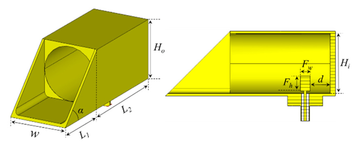
Fig. 1(a) shows the configuration of a designed open-ended waveguide (OEWG) antenna. The antenna consists of an SMA connector, a cylindrical-shaped impedance matching structure, a circular waveguide, and an aperture with an inclined angle of α which can adjust the main beam direction of the antenna [7]. The design parameters are w = 25.83 mm, L1 = 25.83, L2 = 42.12 mm, Ho = 25.83 mm, Hi = 22.83 mm, Fw = 4 mm, Fh = 6 mm, and d = 8 mm.
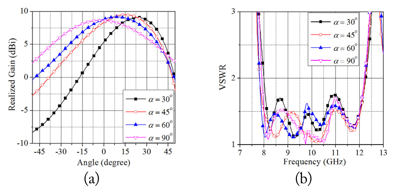
Fig. 2(a) and 2(b) show the radiation patterns on the E-plane and simulated VSWR results of the antenna when the inclined angle of α changes. This shows that the beam steering angle and the maximum gain of the antenna are varied by changing α. The main beam direction of the antenna should be chosen at an angle that minimizes the gain reduction in the front direction of the antenna when the antenna is inserted into the surface of the conductor body. The VSWR results show that the antenna realizes a bandwidth of over 8–12 GHZ (VSWR ≤ 2).
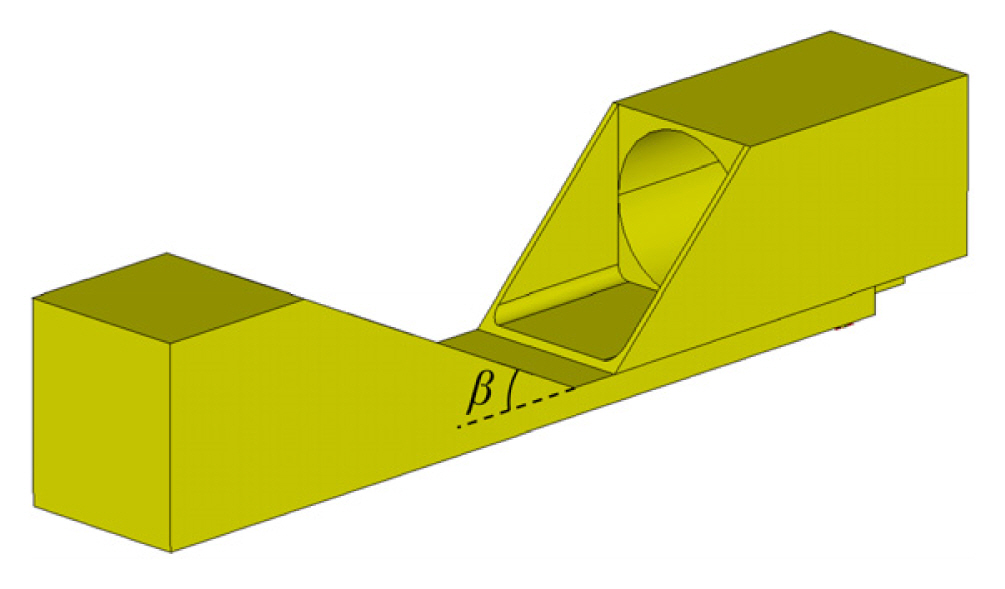
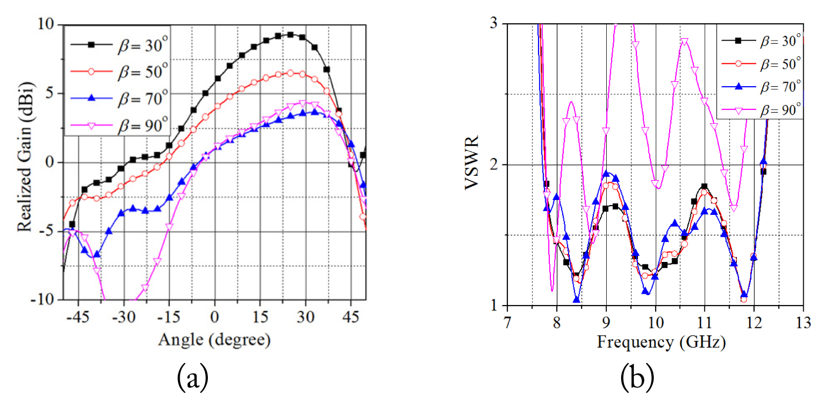
Fig. 3 shows a simplified model when the designed OEWG antenna with α = 45° is inserted into the surface of a conductor body. Here, β denotes the angle of the inclined surface between the antenna and the front conductor body, which affects radiation pattern, gain in the front direction of the antenna, and reflection coefficient. β should be considered together with the main beam direction of the antenna, and it should be selected to minimize the gain reduction in the front direction of the antenna. Fig. 4(a) and 4(b) illustrate the variations of the radiation patterns and VSWR results of the OEWG antenna with α = 45° according to the angle of β changes. From the perspectives of the minimized gain reduction in the front direction of the antenna and operational bandwidth, the angles of α and β are determined to be 45° and 30°, respectively.
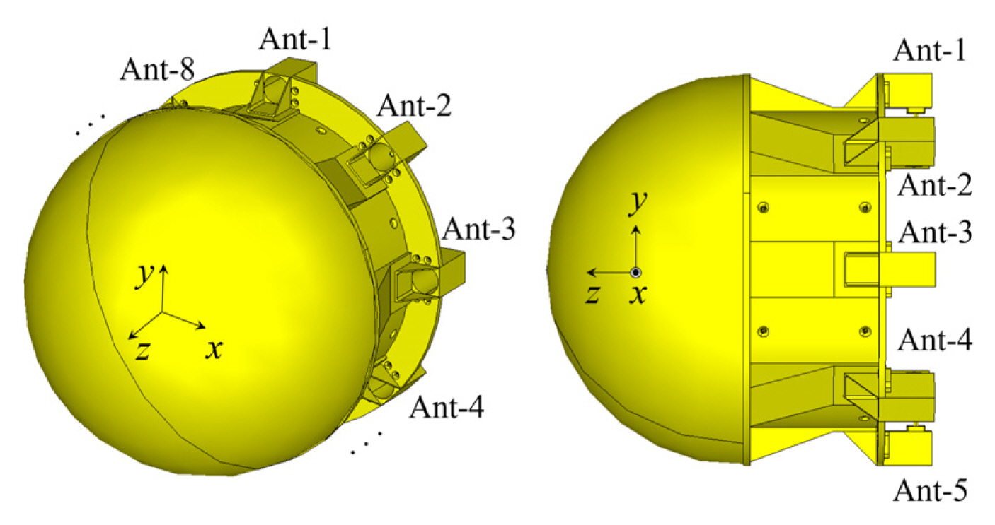
Fig. 5 shows the configuration of the designed DF antenna. The eight OEWG antennas are circularly arrayed and inserted into the surface of the deformed cylindrical conductor, with the hemisphere-shaped conductor located in front of the body. The interior of the body and the hemisphere conductor can be filled or empty, and can include other devices, such as DF antennas. The hemisphere conductor can be replaced by other shapes or materials, such as radome materials.
III. Fabrication and Measurement Results
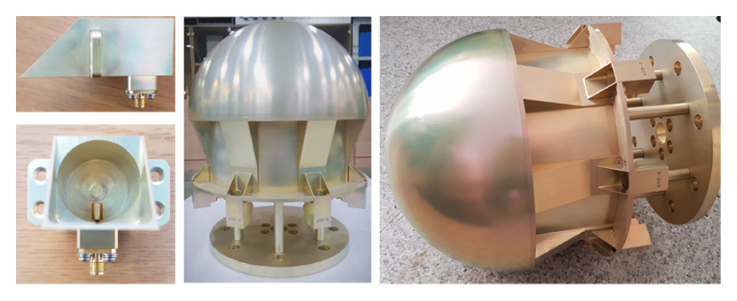
Fig. 6 illustrates the configurations of the fabricated antenna.
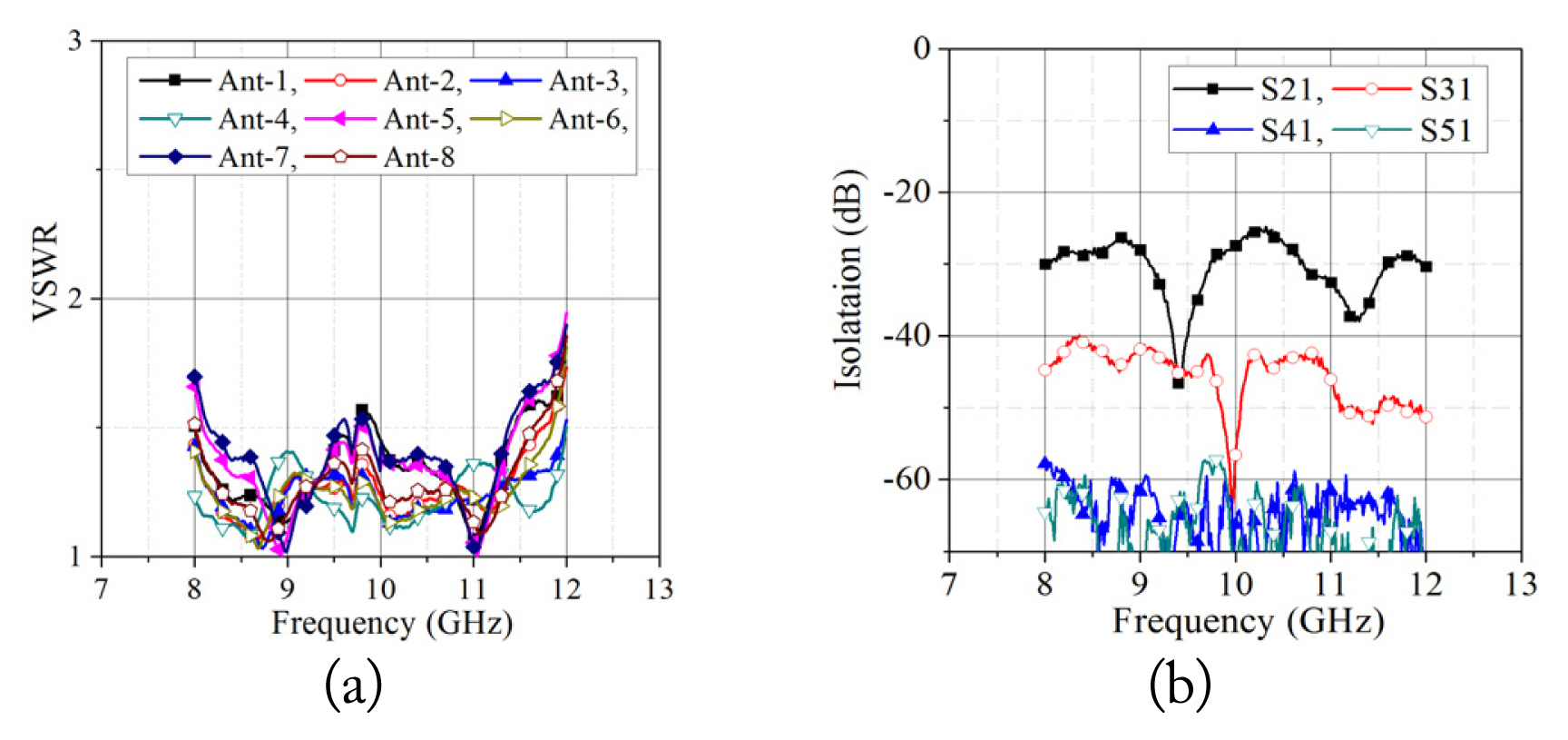
The antenna and the conductor body are made of aluminum. Fig. 7(a) shows that every antenna realizes bandwidths over 8 GHz to 12 GHz. The differences come from assembling errors between the SMA connector and the impedance matching structure. Fig. 7(b) shows that the port isolations are under −25 dB.
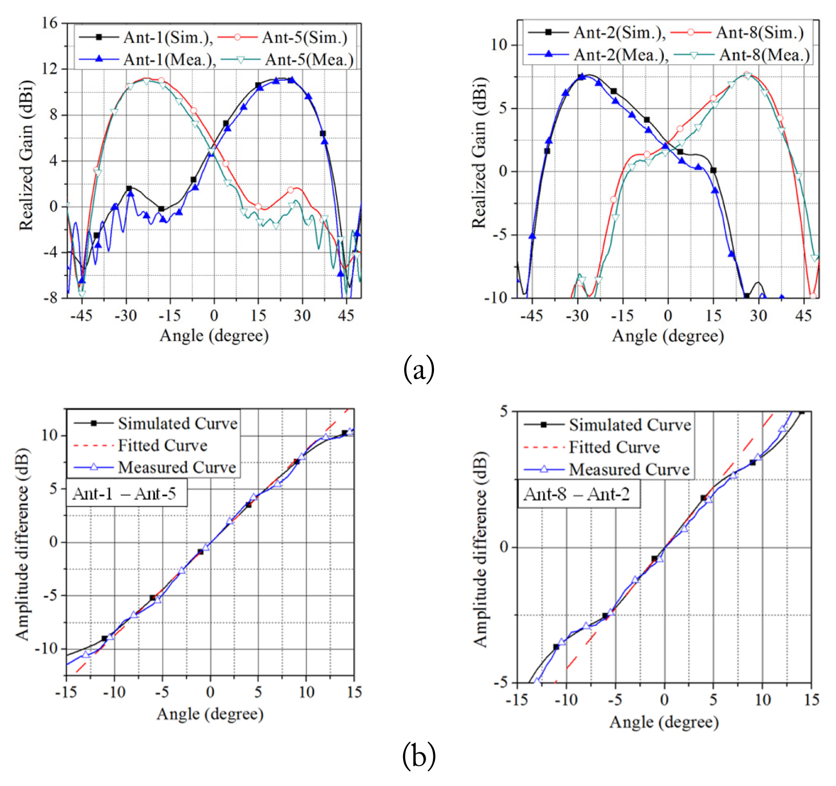
To verify the DF performance of the antenna, a situation is considered in which linear polarization on the y-axis is returned from the target to the antenna. Fig. 8(a) shows the radiation patterns of Ant-1 and Ant-5 and Ant-2 and Ant-8 on the yz-and xz-planes, respectively, where the patterns are calculated and measured using the electric field component on the y-axis direction. Ant-1 and Ant-5 and Ant-2 and Ant-8 perform to find target directions on the yz- and xz-planes, respectively. The gains on the conductor body axis are 5.6 dBi and 2.3 dBi for Ant-1 and Ant-5, and Ant-2 and Ant-8, respectively. The reason for the lower gain of Ant-2 and Ant-8 compared to Ant-1 and Ant-5 is that the electric field component on the y-axis is only considered to receive linear polarization on the y-axis direction. Fig. 8(b) illustrates the amplitude comparison results using the radiation patterns of Ant-1 and Ant-5 and Ant-2 and Ant-8, respectively. The result on the yz-plane shows that the linear slope of 0.87 dB/degree is maintained between −10° to 10°. For the xz-plane, a slope of 0.45 dB/degree is realized, and it is maintained between −6° to 6°.
IV. Conclusion
In this letter, a DF antenna is presented that can be inserted into the surface of a cylindrical conductor body. To minimize performance degradation caused by the front conductor, an appropriate inclined angle of the antenna aperture and deformed conductor body surface are applied. The interior of the conductor’s body can be filled or empty, or other devices can be located within it. Further, other devices, including another DF antenna, can be placed in front of the antenna, because the proposed antenna is designed and optimized with the consideration of front conductor effects. From the perspective of the mounting location and its DF performance, the presented concept can be a good candidate for solving DF ambiguity, which can occur when using a single DF antenna system.