I. Introduction
Wireless power transmission technology has been investigated extensively in recent years and applied to various products, such as mobile electronics, consumer electronics, and electric vehicles [1–5]. In particular, the Qi specification of the Wireless Power Consortium is widely applied to mobile products, such as smartphones [6]. In this magnetic induction-based wireless power transmission, the system performance, including the transmitted power and efficiency, relies on the inverter’s operating frequency, magnitude of the voltage, and coupling coefficient between the transmitting and receiving coils. Therefore, the factors that affect the system design’s performance must be analyzed. As both voltage and power at the receiver load vary according to the system operating frequency, the Qi specification adjusts the operating frequency using feedback control to modify the receiver voltage based on the load condition. Therefore, a frequency-domain analysis is necessary to validate the system frequency response, considering the operating frequency.
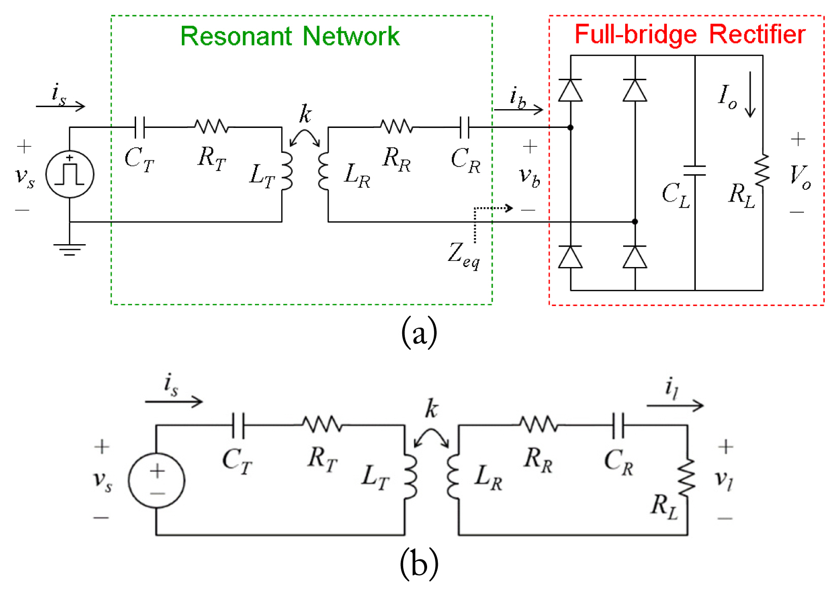
A typical wireless power transfer (WPT) system, as depicted in Fig. 1(a), is similar to the LLC power converter topology. Herein, the received AC voltage is rectified by a bridge rectifier and the DC voltage is supplied to the load. Several studies have used a simplified equivalent circuit model (Fig. 1(b)) to analyze the frequency response characteristics [3–5]. However, the simplified circuit model with a linear load cannot be applied to an actual WPT system design because the resonant network is loaded with an equivalent input impedance of the rectifier circuit (Zeq), which takes into account the nonlinear behavior of the rectifier circuit, including the diode components. Although the equivalent circuit model with nonlinear components can be analyzed in the time domain using a circuit simulation tool, such as SPICE, the non-intuitive time-domain simulation results cannot interpret the system response according to the adaptively changing operating frequency. Therefore, a study proposed a linearized equivalent AC resistance model with the rectifier circuit of the receiver [7], while several researchers have modeled and analyzed the receiver and rectifier using the same model [8, 9]. However, as the model assumes that the forward voltage of the rectifier diode is zero, a considerably large error occurs when designing mobile products that use a relatively small receiving voltage of approximately 5 V. A previous study [10] included the forward voltage of the diode in the model to reduce the error; however, the disadvantage was the requirement for additional experiments for modeling the rectifier through measurements.
To address the aforementioned drawbacks, we propose an iterative method for modeling a WPT system with a nonlinear receiver circuit in this paper. Typically, the linearized equivalent AC model of the receiver that includes diodes cannot be modeled in a closed form due to the dynamic changes in the forward voltage of the diodes based on the receiver current. Therefore, an iterative method was employed to model the converged forward voltage of the diodes and the output voltage in a steady state. The proposed modeling method can be used to accurately identify the transfer response of the voltage reaching the receiver load with respect to the operating frequency in the frequency domain. This can be beneficial when designing a mobile product with a low receiver voltage. The proposed model was validated via circuit simulation, and its accuracy was verified experimentally using a wireless power system based on the Qi specification.
II. Proposed Iterative Method for Modeling a WPT System with Nonlinearity
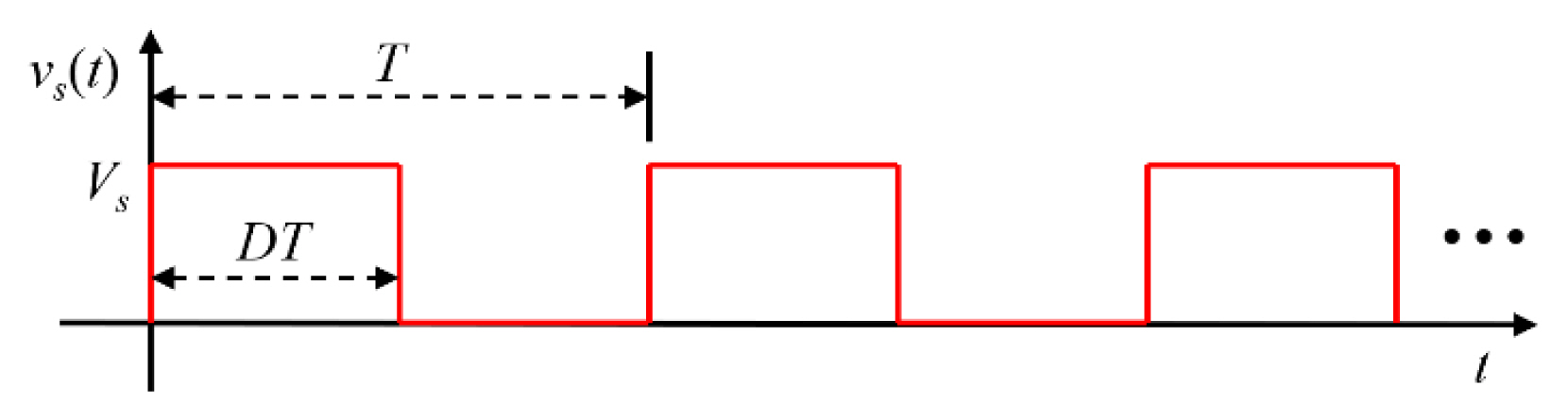
Fig. 2 illustrates the waveform of a unipolar square wave voltage source, vs(t), with an amplitude of Vs, period T, and duty cycle D. Based on the Fourier series expansion, the voltage source can be expressed as indicated in Eq. (1), where h denotes the harmonic number of the order. The square wave source is transferred to the rectifier circuit via the resonant network, resulting in DC voltage at the load.
The resonant network used in this study is designed based on the series–series topology of the Qi standard, which is a typical topology for WPT systems, as illustrated in Fig. 1(b). In the equivalent circuit model, RT, CT, LT and RR, CR, LR denote the equivalent R, C, L components of the transmitting and receiving coils, respectively. The transfer function of the resonant network with a linear load RL can be modeled as indicated in Eq. (2).
Table 1 summarizes the coefficients and design parameters. The resonant network designed with a specific resonant frequency filters the higher harmonic voltages of the square wave source, generating a sinusoidal wave of current in the resonant network. Owing to the higher harmonic rejection properties, a frequency-domain AC analysis can be used in the WPT system modeling with the fundamental component of the square wave source [11]. Moreover, as the inverter in the Qi specification operates at a frequency higher than the resonant frequency in the inductive region, the current flowing in the receiving circuit can be considered as a sine wave. To keep the receiving voltage on a stable level, even with dynamic load conditions in mobile products, the operating frequency should be adjusted in the inductive region, where the transfer function of the resonant network can be controlled mostly linear to the load impedance.
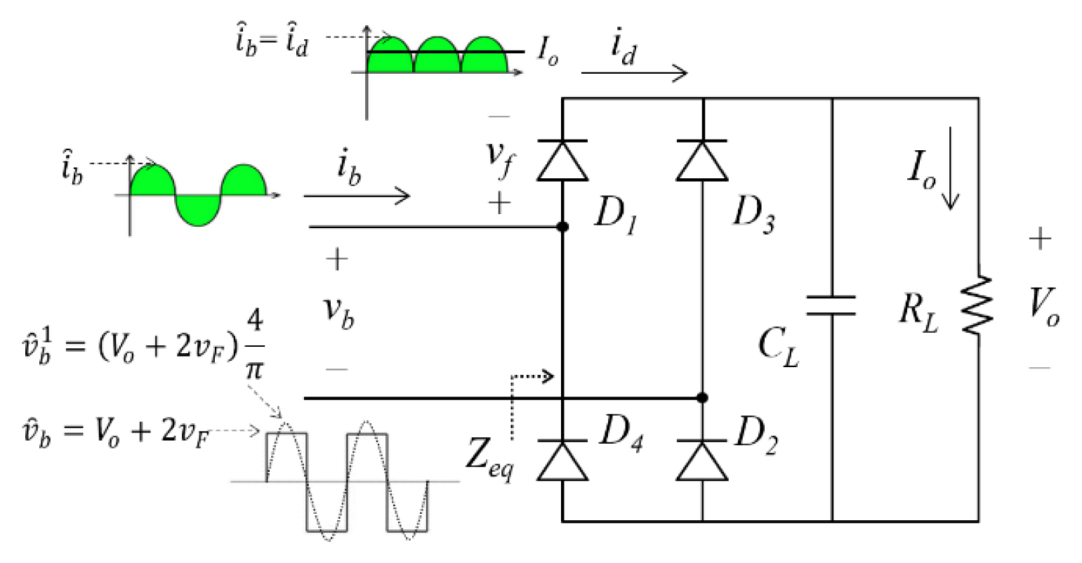
Fig. 3 illustrates the full-bridge rectifier circuit with the input of the fundamental component of the resonant network output current. During the positive half-cycle of the input, diodes D1 and D2 conduct in series, allowing the flow of input current ib, whereas diodes D3 and D4 are blocked; this behavior is reversed in the negative half-cycle. The rectified current, id, is filtered by the smoothing capacitor, CL, connected in parallel with the load, RL, generating the DC output of the full-bridge rectifier circuit. The DC output Io can be obtained by integrating the rectified current, as indicated in Eq. (3).
In the steady state, the amplitude of the input voltage of the rectifier, v̂b, is clamped by the DC output of the rectifier, owing to a voltage increase that is twice the forward voltage of the diodes (vf). Hence, the amplitude of the fundamental component of the rectifier input voltage (
v ^ b 1 v ^ b 1 v ^ s 1
By combining Eqs. (5) and (6), the DC output voltage, Vo, can be expressed as the amplitude of the square wave source, the transfer function of the resonant network, and the forward voltage of the diodes, as indicated in Eq. (7). The input impedance of the rectifier circuit (Zeq), which is defined by the amplitude of the fundamental components of the voltage and current at the rectifier in the fundamental AC analysis, can be obtained by applying Eq. (4) to Eq. (5), as indicated in Eq. (8).
To include the nonlinear characteristics of the rectifier circuits, the proposed modeling method uses the exponential diode model, where IS denotes the saturation current, N indicates the ideality factor, and VT represents the thermal voltage, as indicated in Eq. (9). Considering that the forward voltage of the diodes (vf) is dynamically changed by the diode current, id, which is determined using the output DC voltage Vo, it can be updated by applying Eq. (4) to Eq. (9).
Fig. 4 depicts the proposed iterative method for modeling a nonlinear WPT system. The proposed method begins by initializing the forward voltage of the diodes, vf(0), and the output voltage, Vo(0). Based on these initial conditions, the input impedance of the rectifier circuit, Zeq, is obtained, and the output voltage, Vo(i), is determined with respect to the transfer function of the resonant network associated with Zeq. The output error, Vo_err, is considered the absolute value of the difference between the updated and previous output voltages. If the output error lies beyond the output tolerance range, Vo_tol, the diode current is calculated using the updated output voltage. Additionally, the forward voltage of the diodes, vf(i+1), is updated, which serves as feedback for the next iteration. This forward voltage updates both the input impedance of the rectifier and the output voltage in the next recursion. The proposed method repeats the iteration until the output error falls within the output tolerance range in the converged model. Thus, the proposed method uses the dynamic update of the forward voltage of the diodes and the corresponding output voltage to determine the nonlinear output response of a WPT system, considering the convergence in the steady state.
III. Experimental Verification
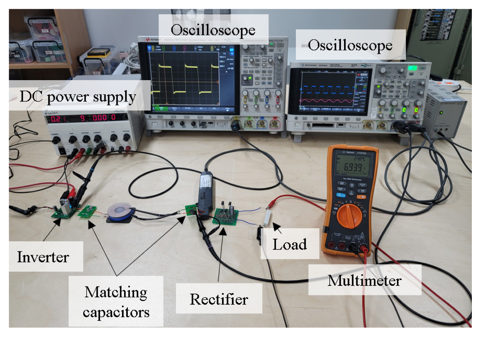
The proposed method was experimentally validated by fabricating a WPT test vehicle based on the Qi standard, and the measurement setup is shown in Fig. 5. The receiver circuit was composed of a full-bridge rectifier comprising four SB350 Schottky diodes with RL = 20 Ω. We used Keysight MSO-X 4154A to measure VS to maintain a constant value of 19 V while changing the system operating frequency from 120 to 210 kHz, where the WPT system operates in the inductive region of the resonant network. Conversely, Vo was measured using an Agilent U1272A digital multimeter. Table 2 summarizes the design parameters of the resonant network, which were determined considering a resonant frequency of 100 kHz. The transmitting and receiving coils with a radius of 43 mm and 44 mm, respectively, were separated by a distance of 7 mm and fabricated to achieve the self-inductances shown in Table 2.
For experimental verification, the output voltage of the test vehicle was estimated using the proposed modeling method. The initial conditions, vf(0) and Vo(0), were set to 0 V and 5 V, respectively, with an output voltage tolerance, Vo_tol, of 10−6. Fig. 6 illustrates the convergence plot of the forward voltage of the diodes and the output voltage as the iteration repeats with an operating frequency of 150 kHz. After eight iterations, the output error attained the tolerance range, and the iteration was terminated with the converged forward voltage of the diodes and an output voltage of 0.60 V and 4.79 V, respectively.
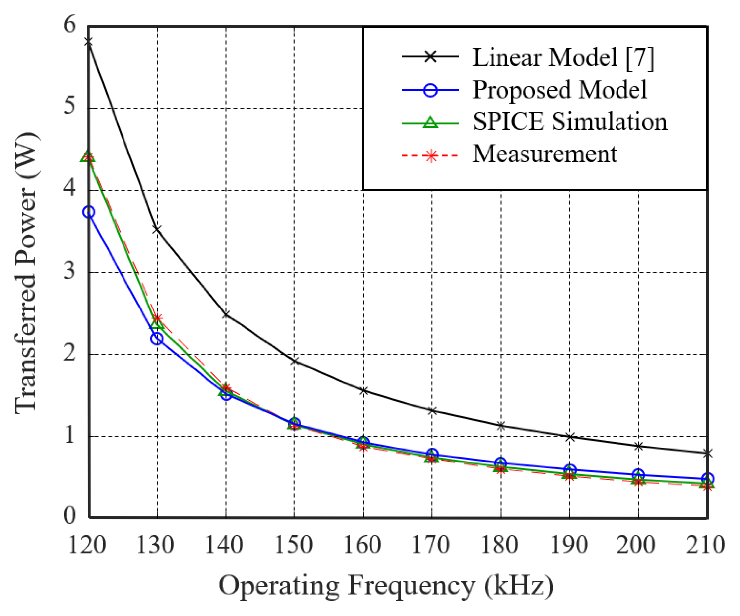
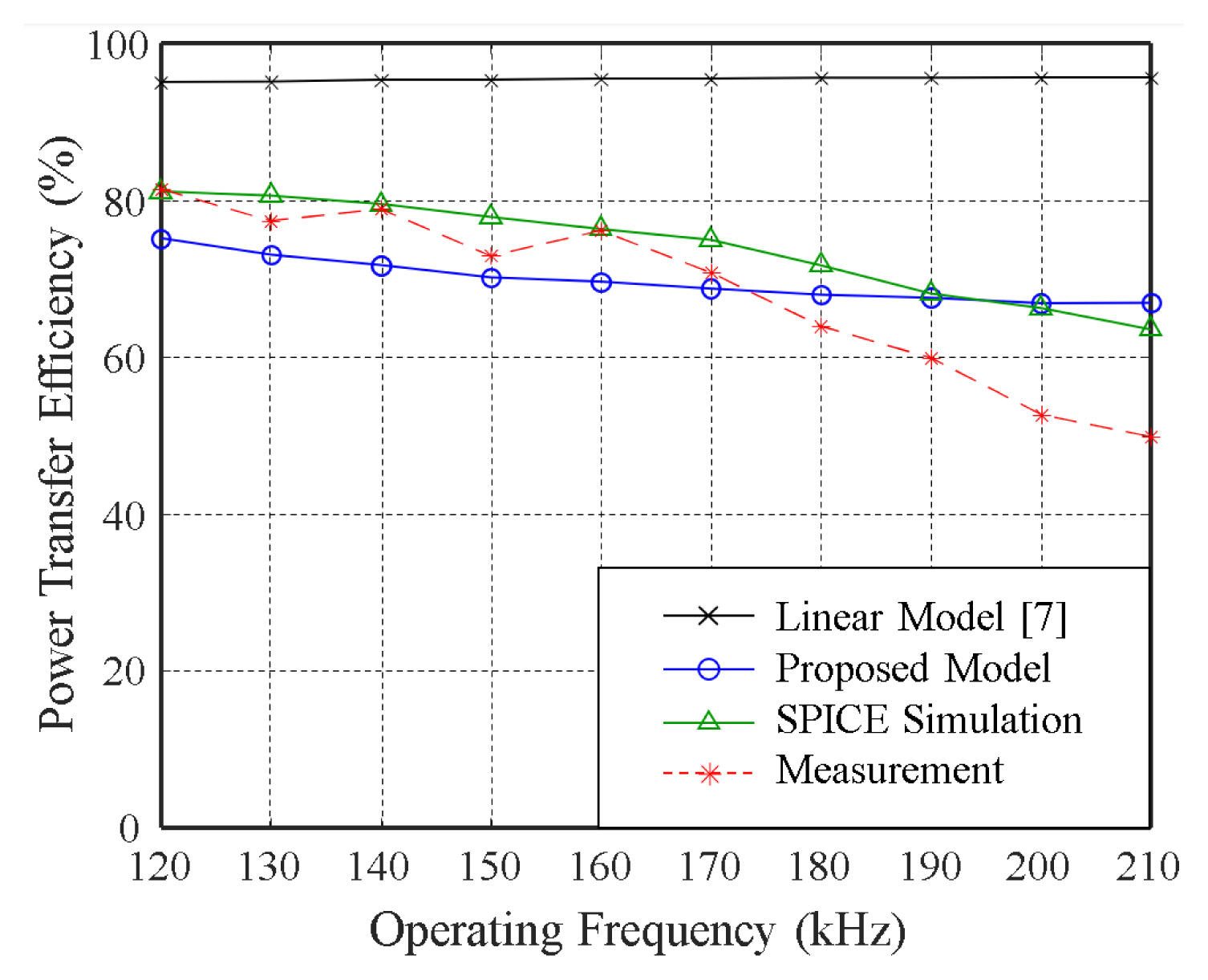
Figs. 7 and 8 illustrate the comparison results of the output voltage and the transferred power at the load, respectively, based on the operating frequency of the square wave source in the reference model, the proposed method, SPICE simulation, and experimental measurements. The classic linear model of the rectifier circuit [7] served as the reference. Unlike the reference model, which ignores the forward voltage of the diodes to achieve AC analysis using a linear model, the proposed method estimated the output voltages using the forward voltage of the diodes converged through the iteration. The proposed iterative method successfully determined the nonlinearity of the diodes based on the fundamental harmonic analysis in the steady state. The output voltage obtained using the proposed method exhibits a prominent correlation with that calculated by the SPICE simulation and measurement results. The discrepancies observed between the output voltage and the transferred power of the classic AC model and the proposed model can be crucial for designing mobile products with low power consumption. If the operating frequency goes out of the inductive region, the fundamental AC analysis is no longer valid and the error of the proposed model increases. The proposed model, on the other hand, is highly valid in the inductive region, where WPT systems in mobile devices actually work in practice. In addition, Fig. 9 shows the comparison results of the power transfer efficiency in the reference model, the proposed method, the SPICE simulation, and the experimental measurements. Unlike the reference model, the power transfer efficiency with the proposed model shows a correlation with those with SPICE simulation and measurement; meanwhile, the discrepancies between them come from the fundamental harmonic analysis of the proposed method, which ignores the higher harmonics of the square wave source.
IV. Conclusion
This study proposed an iterative method for modeling the nonlinearity of a WPT system. The transfer function of the resonant network is characterized in the frequency domain and employed in the fundamental harmonic analysis to obtain the rectifier input. The relationship between the forward voltage of the diodes and the output response is characterized based on the rectifier response in the steady state. Applying this relationship to the diode exponential model, the proposed iteration method dynamically updates the forward voltage through repeated iterations and estimates the converged output response with nonlinearity. The proposed method was successfully validated via SPICE simulation and measurement results, using a test WPT circuit designed based on the Qi standard.