Reduced-Size Series-Fed Two-Dipole Endfire Antenna
Article information
Abstract
The conventional series-fed endfire dipole antenna has a wide impedance bandwidth and is inexpensive to manufacture. However, it has a disadvantage: its size is large because of the large inter-dipole spacing, which is required to satisfy the endfire condition for good antenna radiation characteristics. Here, we propose a two-dipole endfire antenna with a reduced size. The miniaturized endfire antenna was designed using a meander line to reduce the interdipole spacing while ensuring that the endfire condition was satisfied. Furthermore, the overall width of the antenna was reduced using a bent dipole and a corrugated ground plane. The electrical size of the proposed antenna was only 0.33λo × 0.33λo × 0.014λo at a center frequency of 5 GHz, its −10 dB impedance bandwidth was 4.47–5.72 GHz (24.5%), and the gain at the center frequency was 5.9 dBi.
I. Introduction
Recently, wireless communication devices have been gradually miniaturized, and this has led to a continuous increase in demand for small antennas for civilian and military purposes in the wireless communication market [1–6]. Owing to this demand, various types of small antennas are being studied. Conventional printed series-fed endfire dipole antennas are easy and inexpensive to manufacture, and they can be implemented with a wide bandwidth; therefore, they are popular in the wireless communication market [7–12]. However, owing to the large size of the endfire dipole antenna, which results from the dipole length and the interdipole spacing required to satisfy the endfire condition, it is difficult to use a conventional endfire dipole antenna for small wireless communication devices. To overcome this problem, researchers have conducted studies on the miniaturization of dipole arms [13–25]. The electrical length of a conventional dipole is half the wavelength of the center frequency. To reduce the electrical length of the dipole, researchers have studied many types of meander dipole [13–17], bent dipole, and folded dipole structures [18–25]. Furthermore, small zeroth-order resonant dipole antennas with composite right-/left-handed metamaterial structures have been proposed [26, 27]. Although the size of the dipole arm of the endfire dipole antenna can be reduced by using these structures, the phase difference between adjacent dipoles should be between 90° and 180° to satisfy the endfire condition. In a conventional endfire dipole antenna, this phase difference is determined by the interdipole distance. It is difficult to reduce the size of the antenna since the interdipole distance is large [28, 29].
In this study, a meander line was used for the transmission line connecting the dipoles of a series-fed endfire dipole antenna to satisfy the endfire condition while reducing interdipole spacing. Furthermore, a bent dipole and a corrugated ground plane were used to reduce the overall width of the antenna.
II. Two-Element Dipole Antenna
A conventional series-fed two-dipole endfire antenna was designed by connecting two straight dipoles in series with a parallel strip transmission line. The dipoles were matched using a quarter-wave impedance transformer, and their lengths were chosen to be slightly different to achieve a large impedance bandwidth [30, 31]. Fig. 1 shows the geometry of the conventional two-dipole antenna. The substrate used for the antenna was Rogers RO4003C (ɛr = 3.38 and tanδ = 0.0027), and its thickness was 0.8128 mm. The −10 dB impedance bandwidth of the conventional dipole antenna is 4.48–5.56 GHz, and its gain at a center frequency of 5 GHz is 5.9 dBi. The ANSYS High-Frequency Structure Simulator (HFSS) was used to design and optimize the conventional series-fed two-dipole endfire antenna. The optimized design parameters were W = 30 mm, Lg = 10 mm, Wf = 1.8 mm, Ld1 = 25 mm, Ld2 = 19 mm, Sd1 = 13 mm, Sd2 = 17 mm, Wd = 0.5 mm, Wr = 0.5 mm, Wq = 0.3 mm, Lq = 6 mm, L = 41 mm, and S = 1 mm.

Conventional two-element dipole antenna: (a) front view and (b) side view.
Fig. 2 shows the antenna structure that satisfies the endfire condition with reduced spacing; it comprises a meander parallel stripline, two dipoles, and a ground plane. The spacing between the dipoles and that between the dipoles and the ground plane are the same. In a conventional two-dipole antenna, they are connected with a straight transmission line. When the spacing is changed, the length of the transmission line changes; thus, the phase difference also changes. Therefore, the antenna gain is reduced at around the center frequency. To reduce the spacing Sd and to overcome the gain reduction due to the phase difference change, a meander transmission line was used instead of a straight transmission line to connect the radiating elements and the radiating element to the ground plane. The gain in the vicinity of the center frequency was maximized by adjusting the length of the meander line, Lpd, on the basis of interdipole spacing. Fig. 3 shows the characteristics of the antenna for different interdipole spacings. The interdipole spacing Sd was simulated to have values between 3 mm and 12 mm. Fig. 3(a) shows the variation of the reflection coefficient with the frequency for different dipole spacings. The antenna showed good impedance bandwidth characteristics. However, for Sd = 3 mm, the distance between the meander transmission lines was too narrow, and the characteristic impedance of the transmission line was changed, which considerably reduced the impedance bandwidth. Fig. 3(b) shows the gain characteristics of the antenna; the gain around the center frequency was apparently similar, even if the spacing was decreased. The antenna characteristics for different dipole spacings are presented in Table 1. The minimum dipole spacing at which the antenna’s performance was maintained was 4.5 mm. The overall electrical length of the antenna with reduced spacing was 0.33λo, which was about 48.5% of the overall length of the conventional antenna. The impedance bandwidth of the reduced-spacing antenna was 4.53–5.76 GHz, and the gain was 6.2 dBi at the center frequency. The design parameters of the optimized antenna obtained using the HFSS were W = 30 mm, Lg = 10 mm, Wf = 1.8 mm, Ld1 = 25 mm, Ld2 = 19 mm, Sd = 4.5 mm, Lpd = 5 mm, Wd = 0.5 mm, Wr = 0.5 mm, Wq = 0.5 mm, Lq = 6 mm, L = 20 mm, and S = 1 mm.

Spacing reduced printed two-dipole antenna: (a) front view and (b) side view.

Effect of the dipole spacing Sd: (a) reflection coefficient and (b) gain.
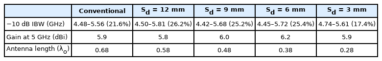
Characteristics of two-element dipole antennas with different spacing
Fig. 4 shows a reduced-spacing antenna with a bent dipole as the radiation element. Owing to the length of the bent portion, Lb, the electric length of the dipole increased, which resulted in a lower center frequency. A parametric study was performed according to the Lb change. Fig. 5 shows the variation in the antenna characteristics with Lb. As Lb increased, the resonant frequency of the antenna decreased, as expected, and the frequency of the peak gain also decreased.

Spacing reduced antenna with bent dipoles: (a) front view and (b) side view.

Effect of bent length Lb: (a) reflection coefficient and (b) gain.
Fig. 6 shows an antenna structure with a corrugated ground plane. The conventional truncated ground plane serves as a reflector, and the ground plane width W strongly affects the antenna’s performance. When the width of the ground plane decreases, the front-to-back ratio and gain of the antenna decrease.
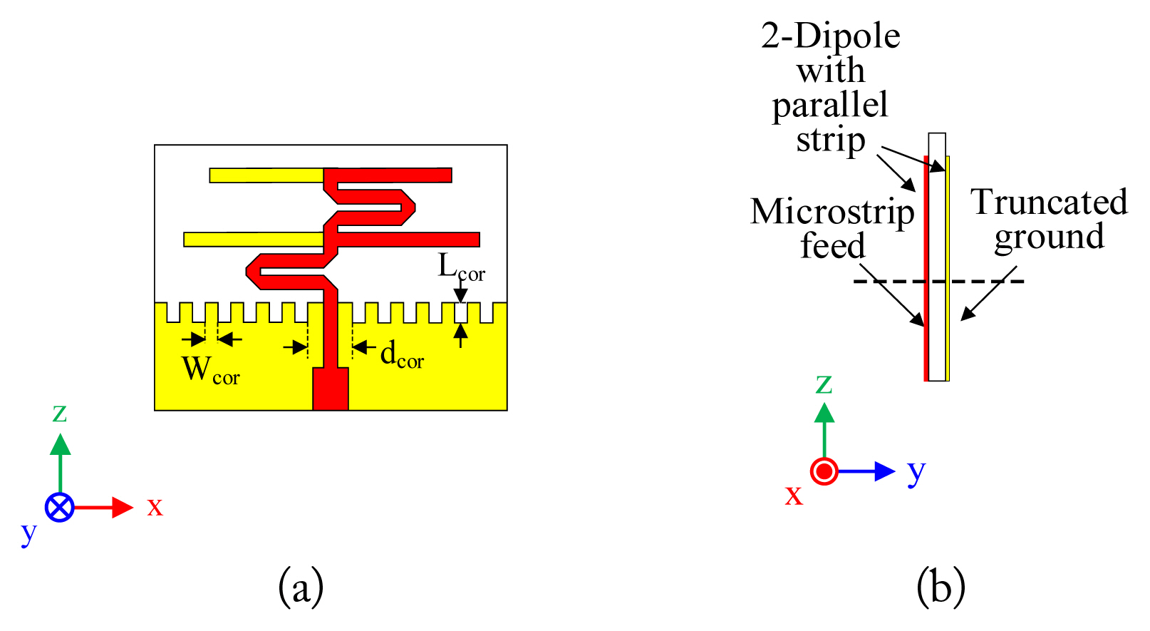
Spacing reduced antenna with corrugated ground plane: (a) front view and (b) side view.
A corrugated ground plane acts as a magnetic ground, and the size of the ground plane significantly decreases with a slight reduction in gain [32]. Corrugation lengthens the edge of the ground plane because the current is concentrated at the edge of the conductor. Therefore, a small corrugated ground plane can perform the same role as a relatively large non-corrugated ground plane. Fig. 7 shows the antenna characteristics at different corrugation depths of a fixed-size ground plane. When the corrugation depth was 3 mm, the impedance bandwidth was maximum, and the center frequency apparently decreased. As shown in Fig. 7(b), the antenna gain decreased as the corrugation depth increased. However, as shown in Fig. 7(c), no significant difference in antenna efficiency was observed within the impedance bandwidth. Fig. 8 shows the surface current distribution of the antenna at 5 GHz without corrugation and the antenna with a 3-mm corrugation depth. Given that the antenna without corrugation was close to the meander line and to the ground plane, a large amount of current was distributed at the edge of the ground plane. In contrast, the antenna with corrugation distributed a relatively small amount of current at the edge of the ground plane due to the effect of corrugation. Most of the current in an antenna with corrugation is concentrated in the dipole and the transmission line, thereby widening the antenna beamwidth and reducing gain.

Effect of corrugation depth Lcor: (a) reflection coefficient, (b) gain, and (c) radiation efficiency.
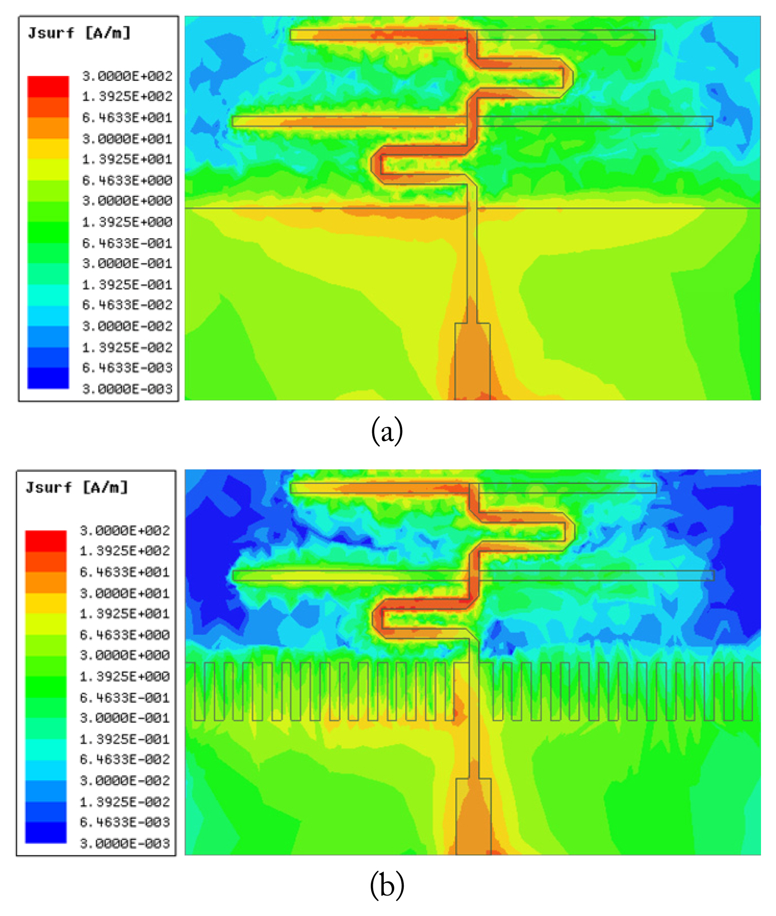
Surface current distributions at 5 GHz: (a) without corrugation and (b) with corrugation of Lcor = 3 mm.
III. Simulation and Measurement
Section II shows the antenna structure used to reduce dipole spacing, dipole width, and ground plane width. By combining these three structures, we designed a small two-dipole endfire antenna in which the interdipole spacing, dipole length, and ground plane width were reduced.
Fig. 9 shows the proposed antenna structure. The antenna size was 0.33λo × 0.33λo × 0.014λo, which was 32% of the size of a conventional series-fed two-dipole antenna. The optimized design parameters of the antenna obtained using the HFSS were W = 20 mm, Lg = 10 mm, Wf = 1.8 mm, Ld1 = 18 mm, Ld2 = 13 mm, Sd = 4.5 mm, Lpd = 5 mm, Wd = 0.5 mm, Wr = 0.5 mm, Wq = 0.5 mm, Lq = 6 mm, Lb = 3.5 mm, Wcor = 0.5 mm, Lcor = 3 mm, dcor = 0.5 mm, L = 20 mm, and S = 1 mm.

Proposed two-element dipole antenna.
Fig. 10 shows a comparison between the optimized reduced-size antenna and the conventional antenna. The impedance band-width of the proposed antenna structure was 4.47–5.68 GHz, which was wider than that of the conventional antenna (4.48–5.56 GHz) by 0.13 GHz. The gain at the center frequency was 6.0 dBi, which was almost similar to that of the conventional antenna (5.9 dBi).

Comparison of conventional and proposed antenna: (a) reflection coefficient and (b) gain.
Fig. 11 shows the fabricated antenna. A Rohde & Schwarz ZVA67 vector network analyzer was used for reflection coefficient measurement, and an MTG anechoic chamber was used for radiation pattern measurement. Fig. 12 shows the simulated and measured reflection coefficients and gains. Fig. 12(a) shows the reflection coefficient. The measured −10 dB impedance bandwidth was 4.47–5.72 GHz, almost identical to the impedance bandwidth in the simulation. Fig. 12(b) shows the gain. The gain measured at 5 GHz was 5.9 dBi, which was almost identical to that in the simulation. Fig. 13 shows the normalized radiation pattern of the antenna at 5 GHz. The simulated and measured values of the half-power beamwidth in the xz-plane were 80° and 94°, respectively, and those in the yz-plane were 139° and 122°, respectively. The measured value of the x-pol level was slightly larger than the simulated value, but the x-pol level was lower than −20 dB. The measured co-pol level and radiation pattern were similar to those in the simulation.
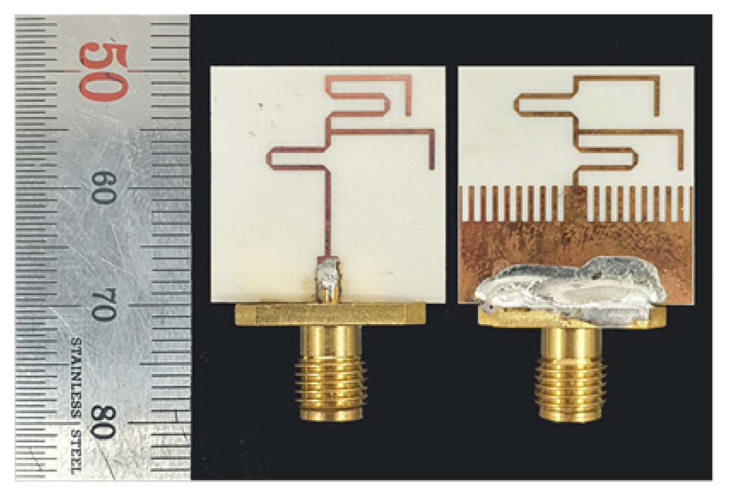
Photograph of the fabricated antenna.
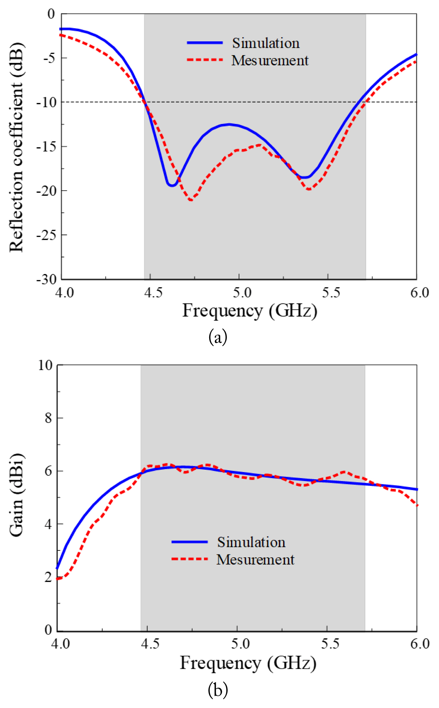
Simulation and measurement of the proposed antenna: (a) reflection coefficient and (b) gain.
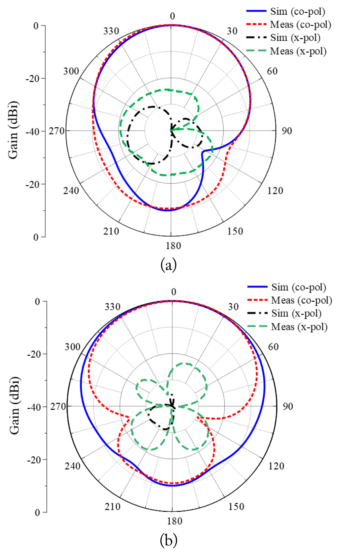
Simulation and measurement of radiation patterns at 5 GHz: (a) xz-plane and (b) yz-plane.
The characteristics of the proposed antenna and the existing endfire antennas with two radiation elements were compared. An endfire antenna using two dipoles of the same size is presented in [8]. Given that the antenna has a large ground plane and that both dipoles operate near the center frequency, the gain is relatively high at 7 dBi. However, the bandwidth of the antenna was only 5.0%. An antenna with an integrated balun that connects two dipoles of different sizes using a coplanar strip transmission line is given in [11]. The antenna had a wide bandwidth of 49.7% due to the integrated balun. However, the gain was 6.0 dBi, which is low in relation to the size of the antenna. A quasi-Yagi antenna using a folded dipole antenna and a director is presented in [12]. This antenna has a gain of 5.5 dBi and an impedance bandwidth of 12.3%. Although its structure is simple, reducing the space between the director and the driven element is difficult. The size of the proposed antenna is only 0.33λo × 0.33λo, the impedance bandwidth is 24.5%, and the gain at the center frequency is 5.9 dBi. The proposed antenna displayed excellent characteristics compared to existing antennas, as summarized in Table 2.

Comparison of existing two-element antennas and proposed antennas
IV. Conclusion
In this paper, a series-fed two-dipole endfire antenna with small size and good characteristics is proposed, comprising a meander line, a bent dipole, and a corrugated ground plane. The size of the proposed antenna is 0.33λo × 0.33λo × 0.014λo, which is about one-third of the size of a conventional two-dipole endfire antenna. The impedance bandwidth and gain at 5 GHz are 4.47–5.72 GHz and 5.9 dBi, respectively, which are almost identical to those of the conventional two-dipole endfire antenna. Owing to its good characteristics, the proposed antenna can be useful in applications that require antennas with a small size, high gain, and wide bandwidth.
Acknowledgments
This work was supported in part by the National Research Foundation of Korea (NRF) grant funded by the Korea government (MSIT) (No. NRF-2022R1F1A106 5324); in part by the National Research Foundation of Korea (NRF) grant funded by the Korea government (MSIT) (No. 2021R1A4A1030775); and in part by Institute of Information & communications Technology Planning & Evaluation (IITP) grant funded by the Korea government (MSIT) (No. 2022-0-00704-001, Development of 3D-NET Core Technology for High-Mobility Vehicular Service).
References
Biography

Heesu Wang received his B.S. and M.S. degrees in Electrical and Computer Engineering from Ajou University, Suwon, Republic of Korea, in 2018 and 2020, respectively. He is currently studying for his Ph.D. degree at the Department of Electrical and Computer Engineering at Ajou University. His research interests include the design of patch antennas, printed antennas, small antennas, and metasurface antennas for various wireless communication applications.

Yong Bae Park received the B.S., M.S., and Ph.D. degrees in Electrical Engineering from the Korea Advanced Institute of Science and Technology, South Korea, in 1998, 2000, and 2003, respectively. From 2003 to 2006, he was with the Korea Telecom Laboratory, Seoul, South Korea. He joined the School of Electrical and Computer Engineering, Ajou University, South Korea, in 2006, where he is currently a Professor. His research interests include electromagnetic field analysis, high-frequency methods, metamaterial antennas, radomes, and stealth technology.

Ikmo Park received the B.S. degree in Electrical Engineering from the State University of New York at Stony Brook, and M.S. and Ph.D. degrees in Electrical Engineering from the University of Illinois at Urbana-Champaign. He joined the Department of Electrical and Computer Engineering at Ajou University in 1996. Prior to joining Ajou University, he has been working with the Device & Materials Laboratory of LG Corporate Institute of Technology, Seoul, Republic of Korea, where he had been engaged in research and development of various antennas for personal communication systems, wireless local area networks, and direct broadcasting systems. He was a Visiting Professor at the Department of Electrical and Computer Engineering, POSTECH, Pohang, Republic of Korea, from March 2004 to February 2005, and the Department of Electrical and Computer Engineering, University of Arizona, Tucson, Arizona, USA, from July 2011 to June 2012. He has authored and co-authored over 300 technical journal and conference papers. He also holds over 50 domestic and international patents. He served as a Chair of the Department of Electrical and Computer Engineering at Ajou University. He is a member of Board of Directors at the Korea Institute of Electromagnetic Engineering and Science (KIEES). He serves as the Editor-in-Chiefs for the Proceeding of the KIEES and Journal of KIEES, an Editorial Board member for the International Journal of Antennas and Propagation, and an Associate Editor for IET Electronics Letters. He served as an Editorial Board member of the Journal of Electromagnetic Engineering and Science. He is also a member of Eta Kappa Nu and Tau Betta Pi.