I. Introduction
Recently, graphene materials have attracted great attention in antenna, microwave, and terahertz applications due to their electromagnetic characteristics. Many graphene antennas have been proposed using graphene conductivity tuning [1–5]. A major class of antennas using graphene materials is the leaky-wave antenna (LWA) introduced in the 1940s [6], whose radiation mechanism is based on a traveling wave inside the structure that leaks outside via a long slot [7]. In general, depending on the structure of the slot, LWAs can be classified into two categories: long slots or periodic apertures [8, 9]. Periodic apertures have been used to better control the leakage constant [10].
The main advantage of LWAs is that they provide a high-directivity beam with no need for a complex and costly feed structure design [11]. Moreover, such antennas have a wide bandwidth capable of beam scanning with frequency, which makes them a suitable choice for 5G and radar applications [12]. However, improving their pattern bandwidth, defined as radiation power density at a fixed observation angle, is an ongoing effort.
Non-radiating microstrip structures can be utilized to create a planar and low-profile LWA. These structures are periodically modulated to create a radiating leaky mode [11]. Metamaterials have also been used to obtain broadside beam angle radiation [13], which could not be attained using a typical LWA. Low-profile LWAs have been presented using substrate-integrated waveguide (SIW) technology [14–16]. In [17], a low cross-polarization SIW-LWA was proposed by placing the slots on the centerline of the SIW.
Recently, research attention has shifted toward working in the terahertz regime due to the demand for high bandwidths and low profiles in new communication networks. A low-loss, low-profile, wide-aperture radar was developed in [18] using a terahertz LWA. More recently, in [19] and [20], two LWAs were presented having wide-angle beam scanning abilities at sub-THz frequencies.
Graphene-based LWAs have also been proposed using the surface conductivity tunability feature of graphene sheets simply by using a DC voltage bias [21–23]. Esquius-Morote et al. [21] presented a leaky-wave terahertz antenna that could alter the radiation beam angle at a fixed frequency using electric tuning. This could be used to increase the pattern bandwidth. Later, Cheng et al. [22] presented a new sinusoidally modulated graphene LWA that could scan the beam angle at a fixed frequency while requiring only one biasing voltage. A graphene LWA that could alter the radiation pattern at a fixed frequency was presented in [23] based on a dielectric grating.
Fuscaldo et al. [24–27] have been working on 2D graphene-based LWAs since 2015. A graphene Fabry–Perot cavity (FPC) LWA has been proposed with the ability to beam steer along both the E-plane and H-plane simultaneously by affecting transverse electric (TE) and transverse magnetic (TM) modes via bias voltage [27]. Different configurations of LWAs based on graphene metasurfaces have also been studied [24]. A systematic approach for modeling homogenized metasurfaces in graphene-based LWAs was presented in [25]. Efforts have also been made to experimentally realize graphene-based FPC-LWAs [28]. New formulas for the beam properties of 1D LWAs have been derived that could provide more accuracy in finite structures [29].
In this paper, a novel long-slot leaky-wave waveguide antenna based on graphene sheets in the terahertz regime is proposed. A novel transverse equivalent network (TEN) model is also presented for a graphene slot. The sidelobe level (SLL) of the antenna is controlled using graphene conductivity over the slot length. The antenna radiation characteristics are tunable across the entire working frequency of the antenna using DC biasing pads under the slot.
Controlling the SLL and other radiation characteristics of the antenna is the main problem addressed in this paper, which is achieved by using graphene conductivity over the slot length instead of the typical way of providing an offset along the slot. This results in a more convenient and dynamic way of tuning the radiation characteristics. A design procedure for a lossy structure LWA with an unknown loss value, is also studied, which has not been previously reported.
The rest of this paper is organized as follows. In Section II, the theory and design principles of LWAs are presented, in which a long-slot leaky-wave waveguide antenna, graphene conductivity, graphene slot TEN, and the antenna design method are discussed. An example of the antenna design and the simulation results are presented in Section III. Finally, conclusions are drawn in Section IV.
II. Theory and Design Principle
In this section, long-slot LWA design principles are discussed, and the variables upon which graphene conductivity is dependent are detailed. Finally, the TEN of a graphene-based slot in a waveguide as part of designing the proposed antenna is described.
TE and TM wave modes are transformed inside a waveguide with dimensions a and b. Waves with frequencies higher than the waveguide cutoff frequency
f c = c 2 a
where η is the antenna efficiency derived from the ratio of the power radiated along the antenna length and the total power input, and A(z) is the aperture distribution over the slot length. The total length of the slot is L. The main beam angle θm of an LWA can be calculated by
where β is the phase constant of the waveguide and k0 is the wavenumber of free space.
In a lossy structure that includes ohmic losses due to non-ideal metal parts or dielectric losses, Eq. (1) is no longer valid. To design such structures with a known loss constant αL(z) over the waveguide length, the radiation constant over the length αR(z) is obtained as follows [30]:
In the presence of ohmic losses, the maximum achievable antenna efficiency for any fixed antenna length L is limited to ηmax, calculated as follows [30]:
1. Long-Slot Leaky-Wave Waveguide Antenna
The radiation of a waveguide slot LWA is based on the power leaking from the slot. The leakage rate is related to the offset of the slot from the center of the waveguide’s side. As the offset increases, more radiation leakage occurs. In a typical long-slot LWA, the slot offset over the length is used to control the antenna SLL.
2. Graphene Conductivity
Graphene is a 2D material whose electric conductivity is calculated as follows [31]:
where qe is the electron charge, KB is Boltzmann constant, T is the temperature, ħ is reduced Planck constant, ω is the angular frequency, τ is the electron relaxation time, and μc is the chemical potential. The chemical potential is tunable by applying a variable DC bias voltage to the graphene sheet. The relationship between the bias voltage VDC and chemical potential is
where Vf is the Fermi velocity in graphene, ɛ0 is the vacuum permittivity, ɛd is the relative permittivity, and t is the thickness of the dielectric. As can be seen from Eqs. (5) and (6), graphene conductivity can be tuned using the DC bias voltage.
If we use a graphene sheet as a slot in the waveguide LWA, changing the conductivity of graphene would alter its leakage rate.
3. Graphene Slot Transverse Equivalent Network
To design a waveguide slot antenna, the value of the leakage rate of the slot over its length is required. A TEN model [32] is presented to calculate the β and α of the structure.
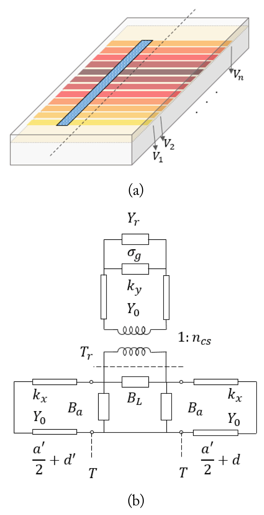
To calculate the propagation and leakage parameters of a graphene slot, we present a transverse equivalent circuit (Fig. 1).
The presented model consists of two parts:
The graphene slot on the upper wall of the waveguide, which is modeled with BL and Ba admittances besides the Tr transformer, transmission line ended by the graphene conductivity σg and radiation admittance YR.
The left and right sides of the waveguide with respect to the center of the slot; each side can be considered a waveguide and can be modeled with transmission lines with
The model is created using the method presented in [33] for waveguide LWAs. To obtain the propagation behavior of the structure, it is reduced to a simple circuit, as displayed in Fig. 2. Yup is the total admittance seen looking up from Tr with graphene conductivity σg and radiation admittance Yr. YR and YL are the total admittance observed from the right and left sides of the slot center, respectively. Now, we have
Setting
Y u p + j B L + Y R Y L Y R + Y L = 0
(10)
where
B a Y 0 , B L Y 0 Y r Y 0
The leakage of the structure consists of two losses: the radiation loss, modeled using Yr admittance, and the loss due to the real part of graphene conductivity.
4. Antenna Design Method
Designing a graphene slot antenna with a specific SLL requires the radiation leakage to be known. The leakage value calculated from the presented model contains both radiation loss and graphene loss. Assuming that the radiation fields near the slot are perpendicular to the graphene sheet with conductivity σg, reflection, transmission, and loss can be simply calculated:
where Z0 is the nominal impedance of the structure.
In the proposed antenna, we have two radiation leakage control parameters: offset from the waveguide centerline and graphene conductivity.
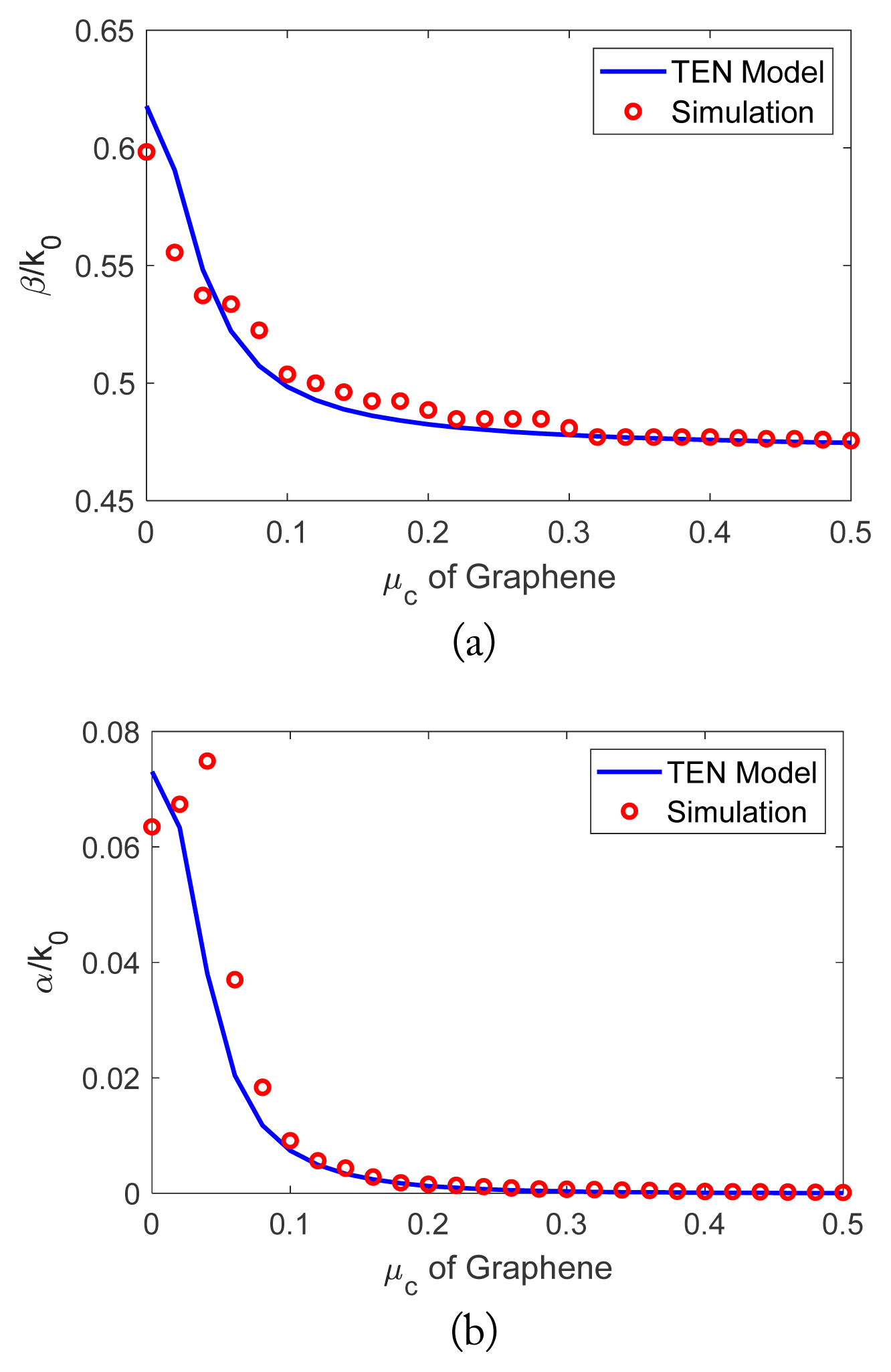
For a fixed offset distance, Fig. 3 depicts the variation of β/k and αr/k versus the chemical potential in a graphene slot waveguide. The waveguide is air-filled, with a = 170 μm and b = 85 μm, so the cutoff frequency is <1 THz, and the tunability range with the graphene conductivity change is clearly shown. The results obtained from the presented TEN and HFSS (High Frequency Structure Simulator) simulations show good agreement, except for the small values of μc due to which α<<β is not justified; therefore, the presented TEN is validated only for higher μc values.
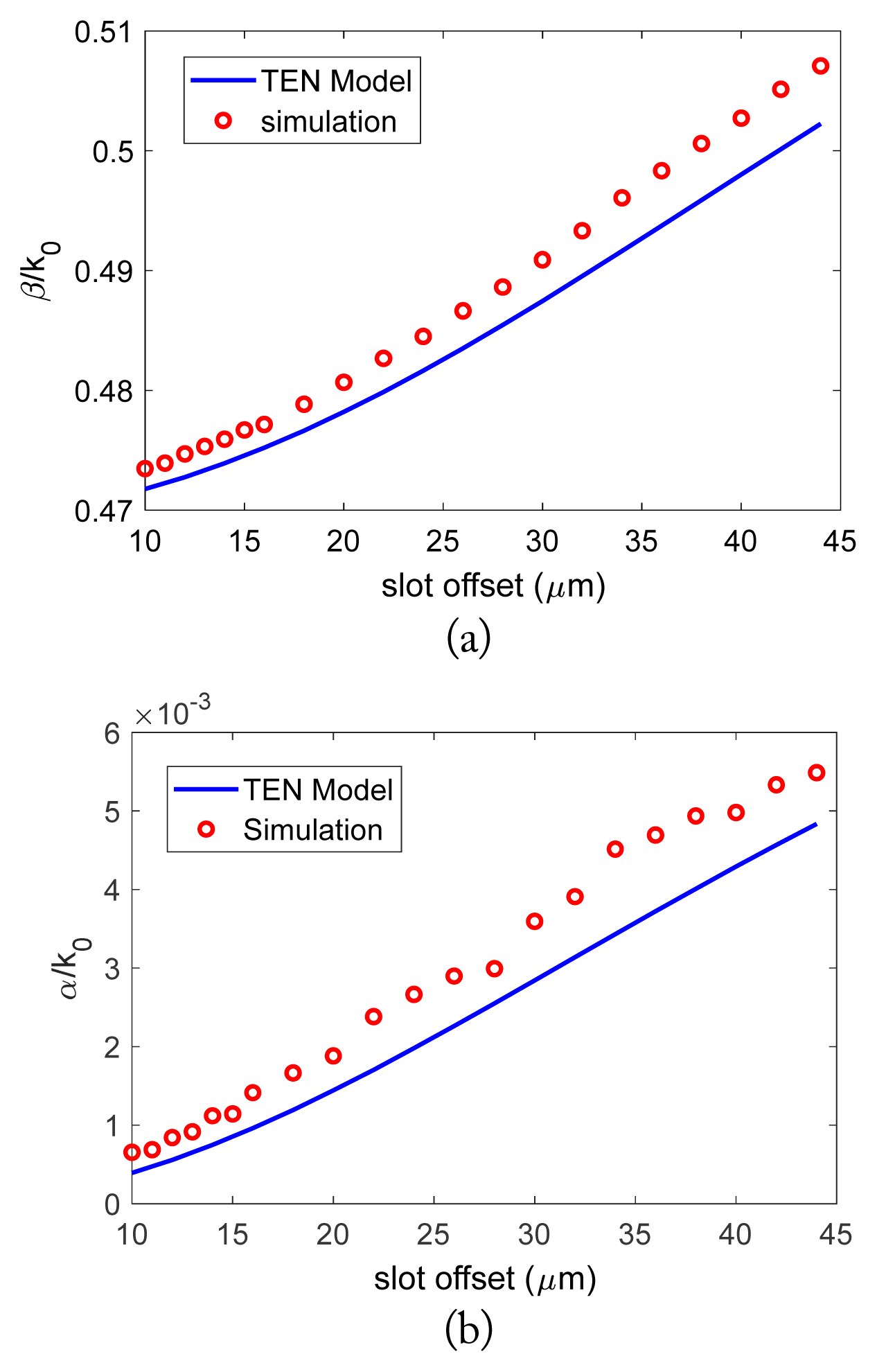
The offset is varied for a fixed chemical potential, and the results are presented in Fig. 4. This shows the tenability of leakage using offset variation.
Varying
β k 0 β k 0 β k 0 = 0 β k 0 = 1
To further simplify the design, we fix the offset of the slot over the length and change the graphene conductivity. This simplifies the manufacturing process. Graphene conductivity can be controlled using DC voltage pads placed under the graphene sheet.
III. Design Example and Simulation Results
A LWA is designed for a main beam angle θm toward 30° at 1 THz. The SLL and the required 3 dB beamwidth are set to −35 dB and 1°, respectively. The dimensions of the waveguide are calculated according to θm and the working frequency as
where a (as depicted in Fig. 1) is the waveguide’s broad wall and ɛr is the electrical permittivity of the waveguide fill material, which in our case is free space and equal to 1. The narrow wall of the waveguide is specified by the maximum power handling of the antenna and is usually defined as b = a/2. Therefore, the waveguide dimensions are a = 173 μm and b = 86.5 μm.
The length of the antenna is obtained according to the 3 dB beamwidth as follows [9]:
where UF is the aperture factor, which is dependent on the field amplitude distribution and is approximately 1. UF is lower for a constant aperture distribution and greater for a sharply peaked distribution, which results in a wider beamwidth. Considering UF = 1 , the antenna length is calculated as L ≈ 19500 μm. Note that in our design, the distribution has a sharp peak due to the graphene loss effects; therefore, higher values for UF are expected, resulting in a wider beamwidth. However, a more accurate relationship is presented in [29], which requires the antenna leakage to be constant along the antenna length. As the leakage is not known at this step, the new formulation is not applicable.
To obtain the desired SLL, a Taylor distribution with −35 dB SLL is to be followed. To avoid grating lobes, the distance between the biasing pads should be equal to or less than λ0/2. Here, it is set to λ0/2 = 150 μm which results in 130 biasing pads.
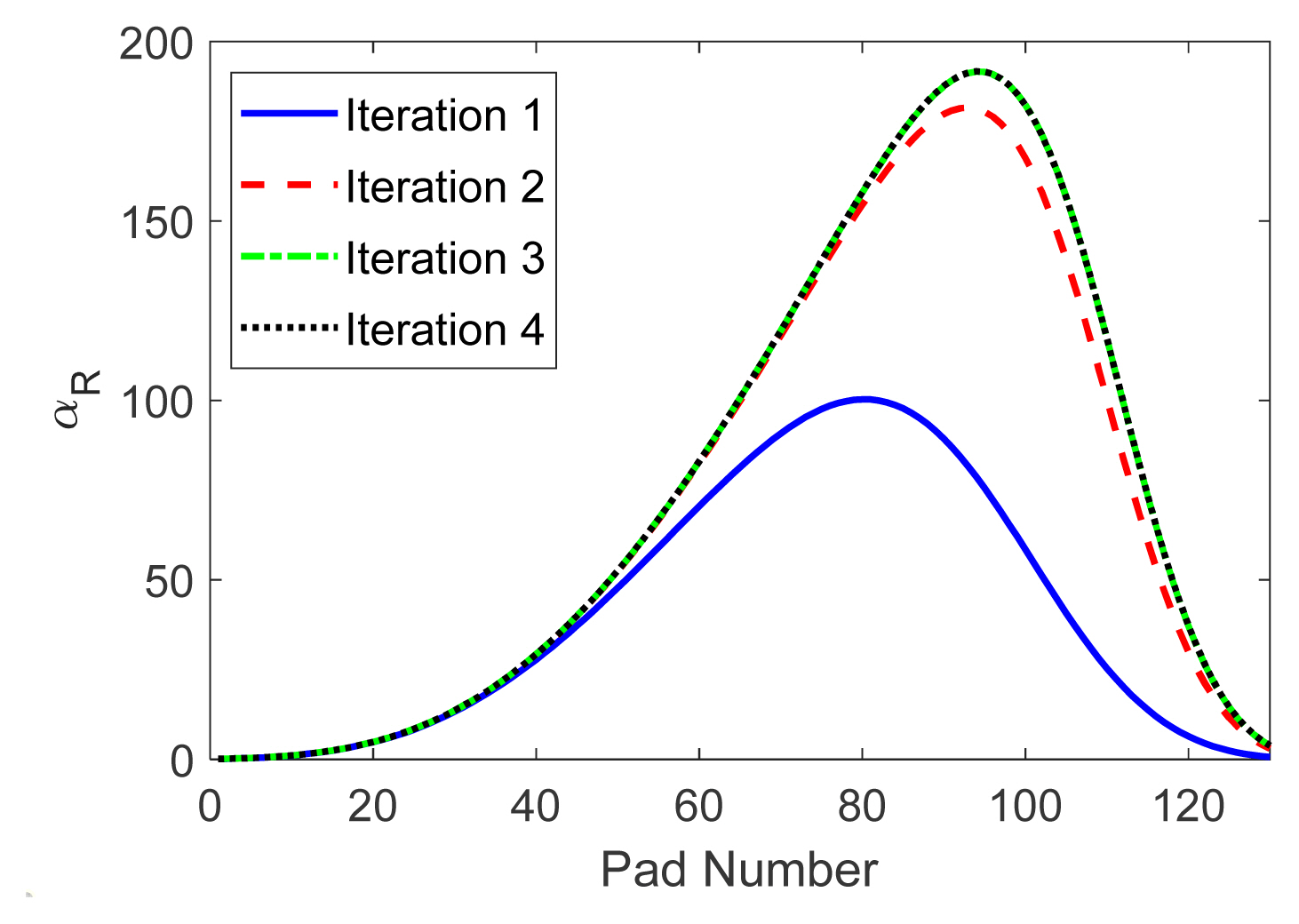
The required leakage over the slot length should be obtained from Eq. (3). When αR(z) is determined, the graphene conductivity and the required chemical potential value under the pads are calculated using Eqs. (10) and (11), respectively. In Eq. (3), the loss constant over the antenna length is considered to be known. However, this is an invalid consideration here, as graphene loss is dependent on graphene conductivity. To overcome such a problem, graphene loss is neglected and αRi is calculated using Eq. (1). After that, an initial value for αL is calculated using Eqs. (12)–(14). Now, the calculation of Eq. (3) is repeated, and the new αR and, consequently, the new αL are calculated. This procedure is repeated until aR and αL converge. The main condition guaranteeing convergence is the value of antenna efficiency η, which should not exceed the maximum value calculated by Eq. (4). The exact value is not known at the onset of the design procedure, so we set it to 70%.
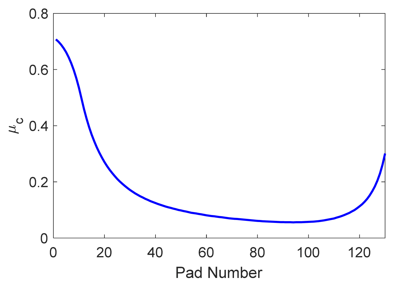
The procedure is followed for four iterations, and the values of αR are illustrated in Fig. 6. The values obtained in iterations 3 and 4 are approximately equal. The final values for the chemical potential along the slot are illustrated in Fig. 7.
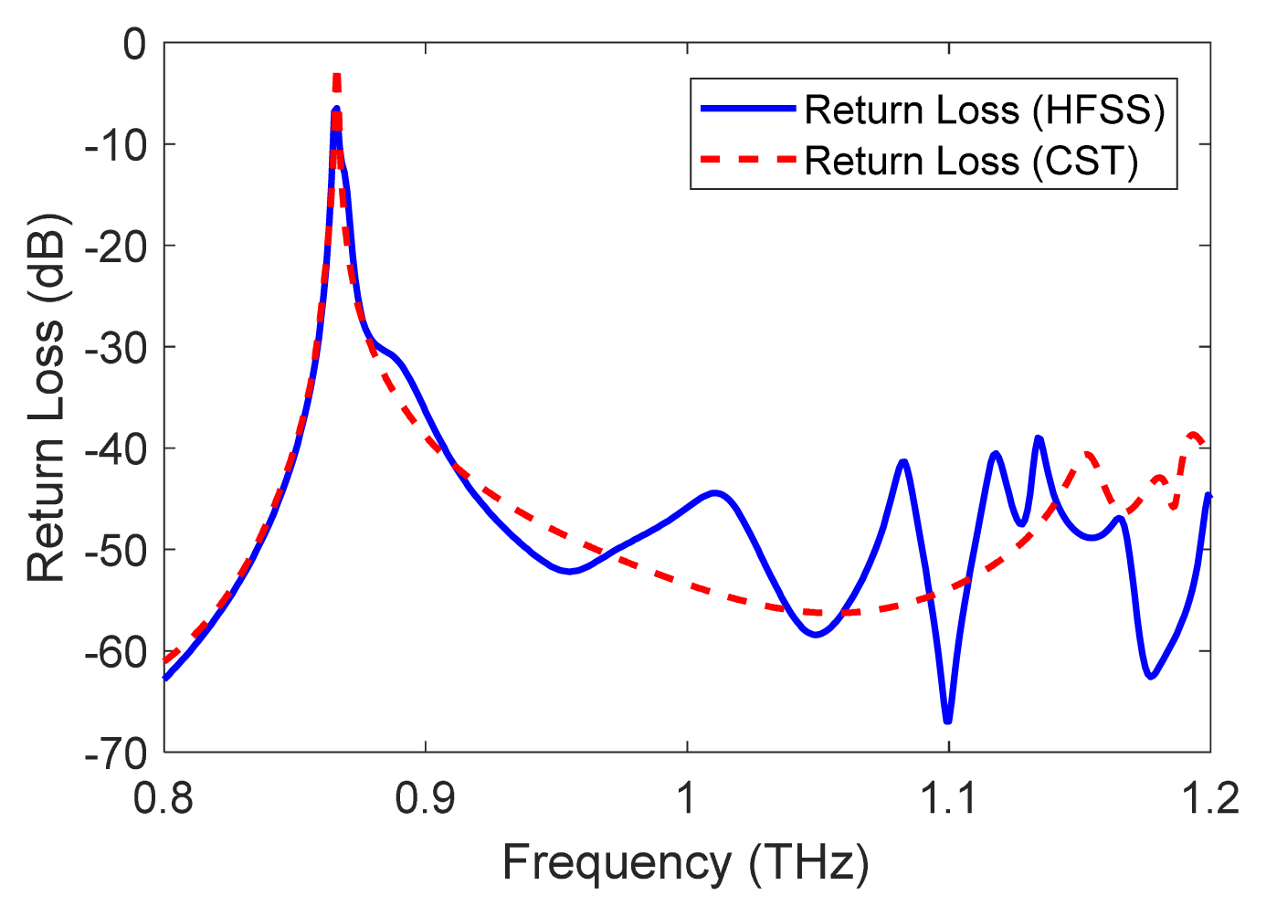
The proposed antenna is simulated using HFSS. Its return loss is presented in Fig. 8. The antenna is also simulated in CST using a different solution method to verify the results. The value of the maximum efficiency obtained is 74%.
The antenna contains a long slot covered by a graphene sheet. A total of 130 silicon pads are placed at equal distance under the graphene sheet to bias each part with different DC voltages.
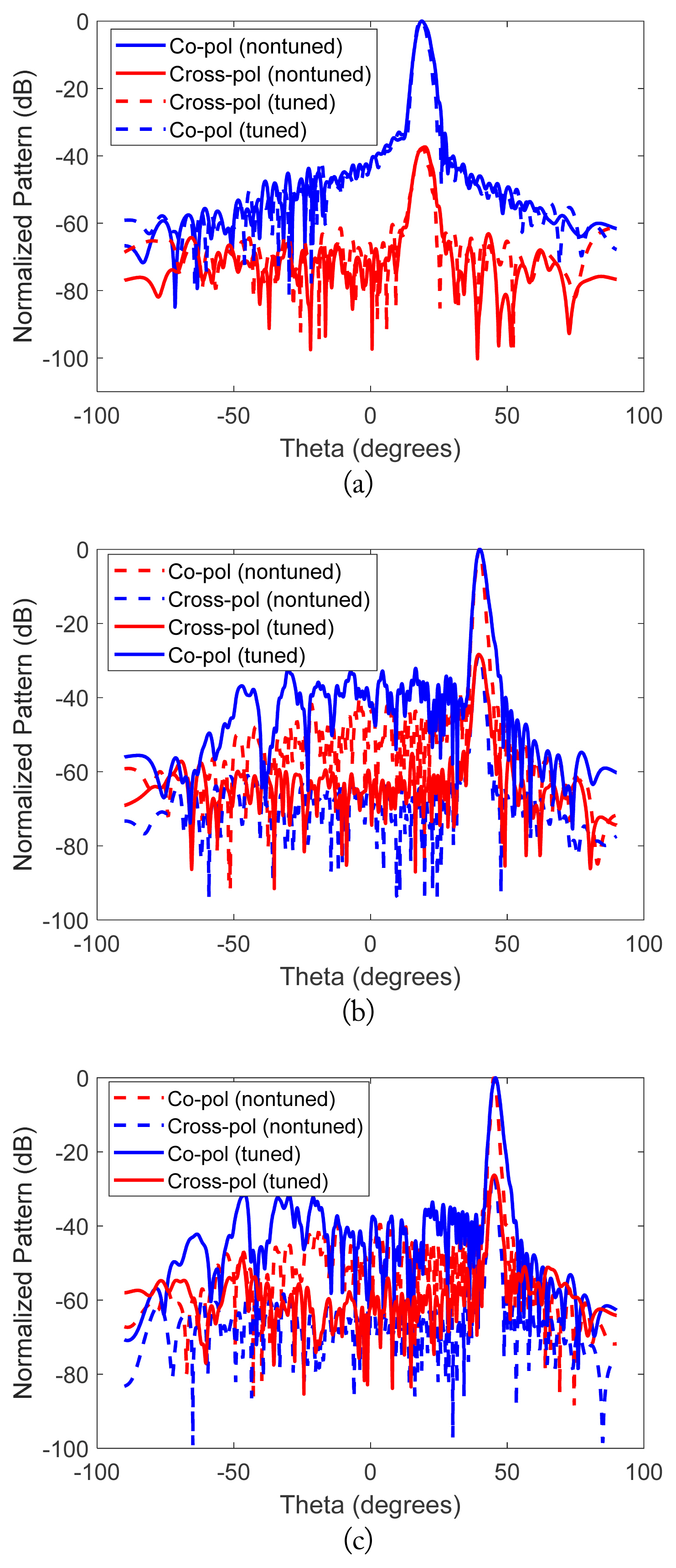
The antenna radiation pattern is also simulated using CST software and compared with the HFSS results (Fig. 9). At the center frequency, the main beam direction is 30° from the antenna’s normal plane. By changing the frequency, the β of the structure varies, and the beam direction will be altered. With a fixed chemical constant, the antenna’s main beamwidth changes with frequency. However, such a problem can be addressed by tuning the leakage constant. This is a beneficial characteristic of the designed antenna, in which the leakage constant can be tuned by changing the chemical potential values over the slot. The new values could be calculated again at each working frequency. A comparison of the antenna patterns between the tuned and untuned values is illustrated in Fig. 10 for 0.9, 1.1, and 1.2 THz frequencies.
A comparison between the presented graphene-based LWA and earlier works is provided in Table 1.
Referring to Table 1, the presented graphene-based LWA is the only design which provides beamforming capability over the antenna’s entire working frequency range. In addition, it is the only antenna that considers graphene loss in the design procedure.
IV. Conclusion
A novel waveguide LWA using a graphene slot is presented. The proposed antenna consists of a straight long slot covered by a graphene sheet on a waveguide working in the THz frequency regime. A TEN model is introduced to model the structure. The conductivity tunability of graphene is used to control the aperture distribution along the slot by means of DC electric biasing pads under the slot. The design procedure is provided while considering graphene loss, and a design example is also presented. The aperture distribution tunability of the antenna over the frequency range is introduced as a beneficial characteristic for controlling the radiation characteristics over the entire working frequency range.