I. Introduction
Microwave and mmWave wireless power transfer (MPT) is a position-free and long-range wireless power transfer (WPT) technology that uses an electromagnetic (EM) field to transmit energy to the receiver (Rx) in radiative near- and far-field regions. Recently, in conjunction with improvements in communication technologies, such as 5G and 6G, MPT has attracted significant attention from academia and industries for powering widespread electronic devices and sensors in homes and offices [1, 2].
The MPT system consists of a power source connected to a transmitter (Tx) antenna system, a wireless channel, an Rx antenna system, and a rectifier circuit that provides direct current (DC) power to the electronics [3]. To develop the MPT system, the DC-to-radio frequency (RF) conversion efficiency of the power source, the power transfer efficiency (PTE) from the Tx antenna to the Rx antenna, the RF-to-DC conversion efficiency, and the DC-to-DC conversion efficiency must be considered. To improve RF-to-DC conversion efficiency, rectennas have been actively studied [4, 5]. In particular, the enhancement method of PTE has been examined in various scenarios [6, 7]. An algorithm to maximize the PTE for charging multiple Rxs was proposed using the optimization problem [6]. The convex optimization algorithm for exciting the Tx antennas of a microwave WPT system that transfers maximum power under a specific absorption rate constraint for human safety was developed [7].
Prior knowledge of the accurate upper bound of PTE for a given Tx and Rx antenna array is essential to the successful design of an MPT system. The number of antennas and the element spacing of the Tx and Rx array antenna should be properly determined in the initial stage of system design. In this study, the PTE bound is defined as the maximum PTE. Many studies have attempted to calculate the PTE of inductive and resonance WPT [8, 9] and MPT [10–15] systems. For instance, Goubau [11] and Shinohara [10] showed that a Gaussian beam is an optimal transmission source between two planar apertures, especially in the radiative near field, and they calculated PTE using the proposed theory. The PTE bound of the radiative WPT was derived for the aperture Tx and a practical mobile antenna [12]. In these studies, the PTE bound was calculated using a continuous source of the Tx, assuming that the Tx is an aperture antenna and that the Rx is an aperture or single antenna. In practical MPT, the Tx and the Rx use array antennas that have discrete element antennas. Therefore, an effective method for calculating the PTE bound of array antennas is needed to design practical MPT systems. Recently, a rough upper bound of PTE was obtained by assuming that the signals received by the Rx element were added in-phase and that Rx elements’ power can be maximized simultaneously and combined [13]. Other research groups have proposed methods to calculate the maximum PTE using a scattering parameter [14, 15]. The PTE can be calculated accurately if a full EM simulator is used to obtain the scattering parameters between the Tx and the Rx of the MPT system. However, the size of the simulation space is limited by the available computer memory capacity, and the simulation time is very long. This is especially true for mmWave WPT because the number of array antennas increases to hundreds [1], and the electrical size increases significantly.
Therefore, we propose a PTE bound estimation method that considers practical array antennas and estimating channels in the MPT system without a computational burden. The convex optimization problem (CVP) is used to estimate the maximum PTE of an MPT system, which can be used as the upper bound of the power received at the Rx under limited transmit power. A CVP is known to guarantee the existence of a global optimum [16]. For the proposed CVP, channel state information (CSI) is estimated using the Friis transmission equation and the active element pattern (AEP) of the array antenna. The PTE bound is obtained by inputting the estimated CSI to the proposed CVP. This method is applied to an MPT system with a Tx and an Rx composed of patch array antennas operating at 10 GHz and 24 GHz, respectively. The PTE bounds are investigated by varying the distance and tilted angle between the Tx and Rx antennas. The required computation time for the methods is also presented. The numerical results are compared with those obtained in previous studies. We obtain the PTE bound more accurately and quickly compared with previous research by using CSI obtained by the AEP and the Friis equation in the proposed convex optimization process.
II. Efficiency Bound Calculation Algorithm
1. System Model and Estimation of CIS
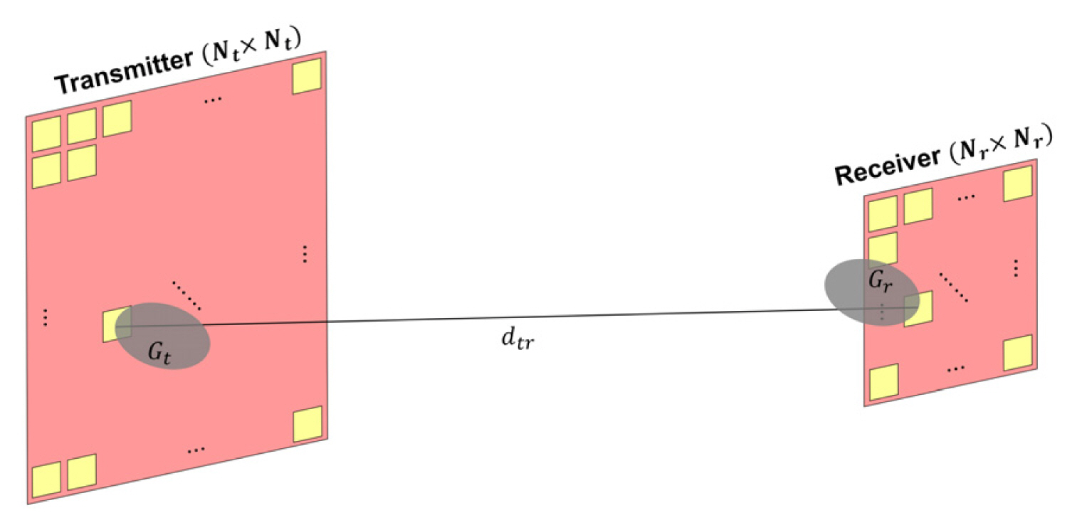
We consider an MPT system in which a Tx and an Rx are array antennas operating at microwave and mmWave frequencies, as shown in Fig. 1. The Tx and Rx arrays are square arrays, as usual [1], and consist of Nt2 and Nr2 antennas, where Nt and Nr are the number of elements per one side of the Tx and the Rx, respectively. In general, the edge effect in which the radiation of the edge element differs from that of the center element occurs in a finite array. However, in the case of an array antenna consisting of hundreds of antennas, the edge effect is quite small in the radiation characteristics of the array because the ratio of the number of edge elements to the total number of elements is small enough to ignore the edge effect. For example, if the size of the array antenna is 16 × 16, the ratio is 14%. In this study, as the Tx and the Rx are assumed to be large arrays, the edge effect can be ignored, and the AEP can be used for the calculation of the CSI. By using the AEP, the magnitude and phase of the CSI can be determined in closed form. In the farfield region of each element of the Tx and the Rx, the magnitude of the CSI is calculated from the Friis transmission equation between element t of the Tx and element r of the Rx array, as follows:
where Gt(θt,ϕt) and Gr(θr,ϕr) are the gain of the elements in angles θ and ϕ with respect to the Tx and Rx normal planes, respectively, λ is the wavelength of the operating frequency, and dtr is the distance between those elements. The magnitude of the CSI in the near field is expressed as [10]:
where τ2=AtArcosθtcosθr/(λdtr)2, and At and Ar are the aperture areas of the elements of the Tx and the Rx. cosθt and cosθr are contained in τ2 to consider angles θ and ϕ with respect to the Tx and Rx normal planes. The phase of the CSI is calculated by converting the distance between each element to phase terms, as follows φ=2πdtr/λ. The PTE results obtained using the estimated CSI and the actual CSI are compared in Section III. In this study, the actual CSI is defined as a scattering parameter between the Tx and Rx elements obtained through a full EM simulation.
2. Optimization Problem for Efficiency Bound Calculation
Let the transmit signal be denoted by xt ∈ ℂNt2×1 and
S = x t x t H
The objective of the optimization is to maximize the power received at the Rx under the transmit power constraint that exists across all Tx antennas denoted by ||xt||2=tr(S)≤Pt, where Pt is the limited transmit power of the MPT system. The aforementioned design problem can be formulated as:
To convert optimization problems (3) and (4) to the CVP, we use the equivalent problem using epigraph form and add the transmit signal constraint, that is,
Optimization problems (5)–(8) are semidefinite programs [14] and CVPs. Therefore, they can be solved by MATLAB software for disciplined convex programming (CVX) [17]. Eq. (8) means that S is semidefinite. It can be said that the transmitted power is constant in this optimization problem because inequality (7) always satisfies the equality condition when the optimization problem is solved completely. The proposed optimization problem maximizes the total received power with constant transmitted power, so it is considered to be a problem of maximizing the PTE. The maximum efficiency of the MPT system can be obtained using the estimated CSI and the proposed optimization problem. In this study, the PTE under the condition of the MPT system is defined as Pr/Pt.
We executed the PTE bound estimation method using the following process. First, we determined the specifications of the MPT system. Second, we designed the element of the array antenna and obtained the AEP. Third, the CSI was estimated using the designed element antenna, the distance between the Tx and the Rx, and the tilted angle of the Rx relative to the broadside of the Tx. Finally, the estimated CSI was fed to CVPs (5)–(8), and we obtained the PTE bound using the calculated maximum PTE.
III. Numerical Results and Discussion
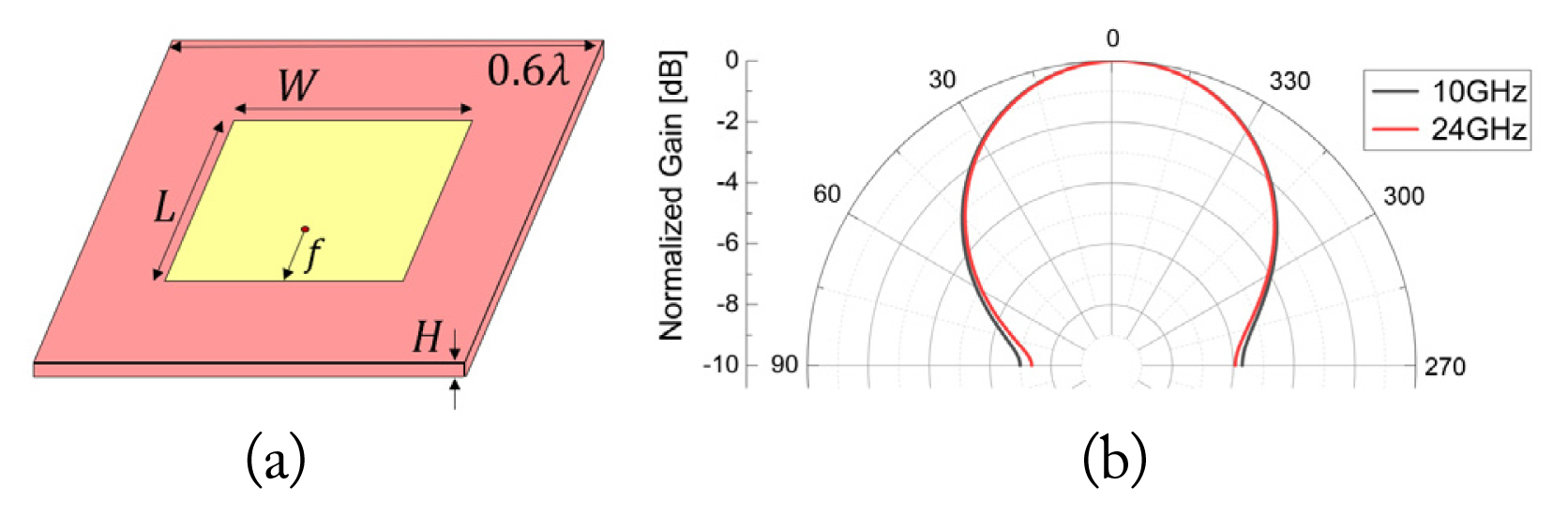
In this section, we present the simulation results to validate the proposed method. The MPT system consisting of a Tx and an Rx, which are square array antennas, was considered as shown in Fig. 1. The AEP was obtained using unit cell simulation in CST Microwave Studio. The element antenna was a microstrip patch antenna operating at 10 GHz and 24 GHz, designed on a Taconic TLY-5 dielectric substrate with relative permittivity of ɛ = 2.2, loss tangent of 0.00009, and the length of one side of 0.6 wavelength, as shown in Fig. 2. The design parameters of the patch element for each operating frequency are listed in Table 1. The gains of the element antennas were calculated using the AEP, as shown in Fig. 2. The PTE results of the proposed method were obtained using MATLAB and CVX.
1. PTE Variation with Distance
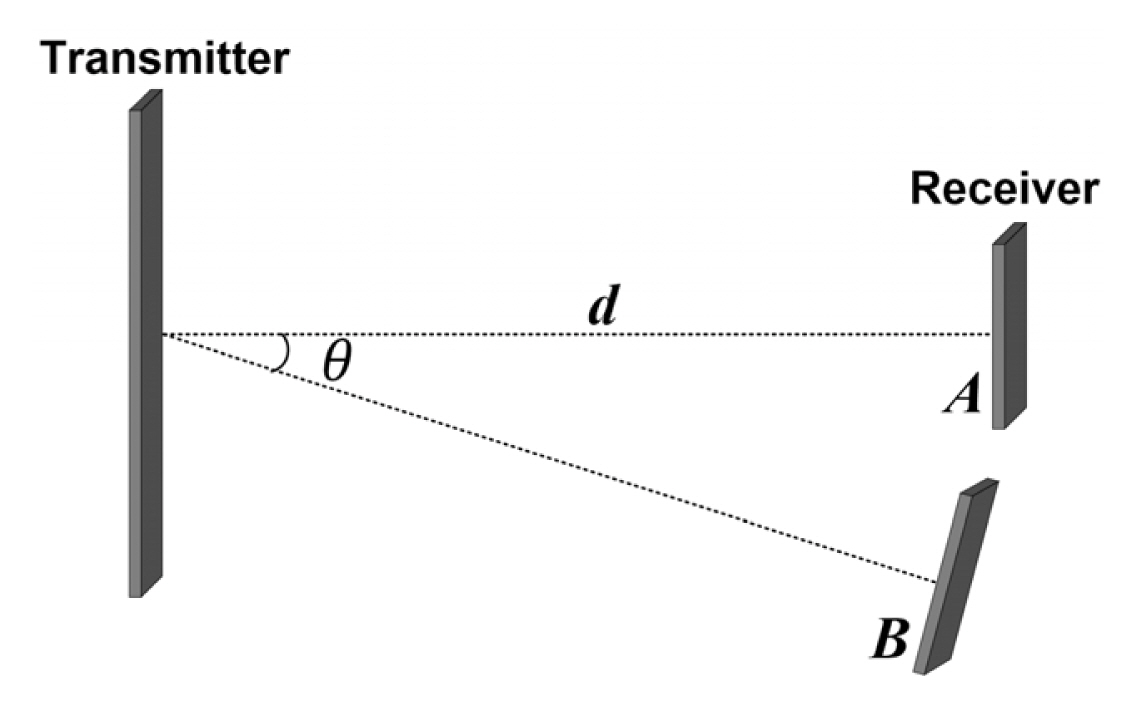
The distance d between the Tx and the Rx was varied under the condition of fixed physical sizes of the Tx and the Rx, as shown in Fig. 3. These were fixed to 0.15 m × 0.15 m and 0.06 m × 0.06 m, respectively. The number of antenna elements in the array was set according to physical size, the spacing between elements, and the operating frequency. As we designed the single-element antenna structure with a size of 0.6 wavelength, the number of (Tx, Rx) elements was determined as (11 × 11, 4 × 4) and (26 × 26, 10 × 10) at 10 GHz and 24 GHz, respectively. The PTE bound of the proposed method was compared to those in [11] and [13], as shown in Fig. 4.
We calculated the PTE bound using the actual CSI over 500 mm intervals to validate our study. To obtain the actual CSIs, the entire MPT system shown in Fig. 1 was simulated using the time-domain solver of CST Microwave Studio running a computer with two NVIDIA Tesla V100-PCIE-32GB graphics processing units (GPUs). Even with GPU acceleration tokens, the computer required 121 hours to obtain three points (500 mm, 1,000 mm, and 1,500 mm) in the case of 24 GHz, whereas the estimated CSI was obtained in 5 minutes. The estimated CSIs were calculated using MATLAB with the Tx and Rx parameters, such as the number of element antennas, spacing, and AEPs. The time to obtain an AEP using a full EM simulation was less than 2 minutes. The computation time for the actual CSI was significantly large because the electrical size of the MPT system was enormous in mmWave, and the full EM simulation was iterated using the same number of times as that of the Rx elements.
We can observe that the PTEs calculated using the proposed method are in good agreement with those calculated using the actual CSI. The error between the PTEs of the actual and the estimated CSI is defined as (PTEestimated CSI – PTEactual CSI)/PTEactual CSI. The average errors of 10 GHz and 24 GHz are 5% and 3.9%, respectively. These results demonstrate that the proposed method accurately reflects the practical MPT system. The small discrepancy between the results using the proposed CSI and the actual CSI is a result of the limited number of mesh cells in the EM simulation and the difference between the AEPs and the actual radiation pattern of the antenna elements in the finite array. More than 2.4 billion finite-difference timedomain (FDTD) mesh cells are required to obtain an accurate actual CSI in the 24 GHz scenario. However, the number of mesh cells that can be simulated is limited to 2.4 billion. Therefore, we reduced this even if the actual CSI accuracy was lower.
The PTE bounds of [11] and [13] are equal and show the maximum upper bound. As we mentioned in the introduction, the Tx and the Rx were apertures in [11], and the powers received at the Rx elements were independently maximized in [13]. This means that the PTE bound was roughly calculated as the largest value. The PTE bound of the proposed method is lower than that of [11] and [13] in the entire region. At a distance of 1 m and a frequency of 24 GHz, the PTEs of the proposed method and [11] are 66.8% and 74.6%, respectively. This means that the PTE bound of [11] is larger than that of the proposed method by a 11.6% ratio. At a distance of 1 m and a frequency of 10 GHz, the PTEs of the proposed method and [11] are 20.2% and 18.2%, respectively. This means that the PTE bound of [11] is larger than that of the proposed method by a 10.9% ratio. As the distance increases, the PTE bound of the proposed method and that of [11] and [13] become closer, as the beam focusing by the optimization algorithm becomes the same as the conventional beamforming using a transmit signal of the same magnitude and phase.
The results show that the PTEs at 24 GHz are consistently larger than those at 10 GHz. This is because the focusing capability of the array antenna increases as the electrical size of the array increases. In the case of the far-field region, the antenna gain is approximately expressed as 4πA/λ2 for an array with a physical size A. Conversely, in the case of the near-field region, the difference between PTEs at 10 GHz and 24 GHz is reduced because the distance is close, and most transmit power is transferred to Rx in both cases. It is noticeable that the higher the frequency, the larger the PTE for the Tx and Rx arrays of the same size. This suggests that frequency selection is important to determine the size of the Tx and the Rx when the desired MPT system specifications, such as PTE and range, are provided.
2. PTE Variation with a Tilted Angle
A PTE estimation when the Rx is tilted from the broadside of the Tx is required for the MPT system design. Therefore, the PTE was calculated according to the tilted angle θ of the Rx at a fixed distance of 1 m from the Tx, as shown in Fig. 4. The physical sizes and numbers of the Tx and Rx elements were the same as those in Section III-1. The PTE bounds of [11] are the uppermost bound, as with the results in the previous section. At an angle of 50° and a frequency of 24 GHz, the PTEs of the proposed method and [11] are 58.5% and 30%, respectively. This means that the PTE bound of [11] is larger than that of the proposed method by a 95% ratio. The PTEs using the proposed method agree well with those using the actual CSI. These results indicate that the proposed method can provide a tighter PTE bound than the other methods can and that it can be applied to the design of practical MPT systems.
The greater the tilted angle of the Rx, the lower the PTE at 10 GHz and 24 GHz. This is because the element gain of the RX is lower when the tilted angle is greater. In the case of 24 GHz, the total computation times to obtain three points (10°, 30°, and 50°) using the actual and estimated CSI were 151 hours and 5 minites, respectively. This demonstrates that the proposed method can be used to obtain the PTE bound accurately with much less time than the other methods can.
IV. Conclusion
In this study, we proposed an efficient PTE bound estimation method for practical MPT system design with a minimal computational burden. The maximum PTE of the MPT system was obtained using the estimated CSI and the proposed CVP. For a fast and accurate PTE bound calculation, the CSI was estimated using the Friis transmission equation and the AEP of the array antenna under the assumption that the Tx and the Rx are large arrays. The proposed CVP was formulated to maximize the received power under the transmit power constraint; therefore, the proposed CVP can maximize the PTE of the MPT system. For an MPT system operating at 10 GHz and 24 GHz, we calculated the PTE bound using the proposed method and compared it with those obtained using previous methods. The PTE bounds were obtained by varying the distance and tilted angle between the Tx and Rx antennas. Analyzing the results according to the distance, it was found that the PTE bound obtained by the previous method was, on average, 10% larger than that of the proposed method using the actual CSI. In addition, we showed that the PTE bound using the estimated CSI was, on average, 3.9% larger than that using the actual CSI obtained by the full EM simulation. The simulation time for obtaining the PTE of the proposed estimation method is several thousand times shorter than that of previous methods. Therefore, the proposed optimization method for obtaining the PTE using the CSI estimation method is accurate and significantly shortens the overall simulation time of the WPT system. It is expected that the proposed method can be applied to determine the design parameters of the MPT system, such as the number of element antennas and the spacing between the element antennas of the Tx and the Rx.