I. Introduction
In modern society, critical infrastructure such as transportation facilities, hospitals, and administration buildings are becoming increasingly complex and larger than in the past. Each point of critical infrastructure is interconnected using a wireless system, and electromagnetic waves are used as an important resource. During the operation of electrical systems, the malfunction of wireless systems caused by radiated electromagnetic disturbance can lead to severe and even deadly consequences in many fields. Hence, various studied have focused on preventing such threats in advance. In particular, full-wave numerical analysis techniques based mainly on Maxwell's equations have been used to solve and estimate this problem. However, this technique is inefficient, since the larger and more complex the target, the more time and data are consumed. Also, additional hardware devices and high-precision modeling must be used to increase the accuracy and efficiency of such techniques. In other words, the characteristics of modern structures, which are large and complex, highlight the disadvantages of numerical techniques.
In this paper, we use the electromagnetic topology/power balance (EMT/PWB) method as a theoretical approach to perform efficient electromagnetic wave environmental analysis in a large-scale structure. When using the EMT method [1], the space or structure to be analyzed is categorized into several regions depending on their energy level and modeled equivalently as a topological diagram. In the PWB method, the analysis is performed probabilistically using conditions such that when the dimension of the structure to be analyzed is much larger than the target wavelength, electromagnetic waves are uniformly distributed inside the structure, and the amount of transmitted power to the target and the amount of total internal dissipated power are the same as in the steady state condition. The initial concept of this method was proposed in [2, 3], and the method has been applied to electromagnetic wave analysis in a simple structure [4–6]. In addition, the utility of this method has been verified [7], and research on electromagnetic wave analysis in complex large-scale structures has been carried out and cross-validated using this method along with a commercially available simulation tool [8, 9]. To derive the shielding effectiveness of a large structure, such as civilian structures, research was performed to compare the measured results with those calculated using the EMT/PWB method [10]. Nevertheless, the published concept of this method has been proven to be valid only for structures made of conducting materials. Therefore, using a commercially available simulation tool, research was conducted to consider not only conductors but also building materials with general electrical properties when this method was applied. The performance-enhanced PWB (PEPWB) method was proposed to enhance the published performance of the PWB method [11]. The PEPWB method, unlike PWB, considers the transmission characteristics of materials other than conductors.
Furthermore, looking at mostly civilian structures, there are many surrounding external environmental factors, including vegetation (trees), flower gardens, and outdoor machines. Therefore, the electromagnetic waves propagating from outside the structure to the inside will be affected by these environmental factors. In particular, there is a high possibility that electromagnetic waves are attenuated by trees. In general, the electromagnetic wave attenuation phenomenon caused by trees is influenced by various factors, such as their type, electrical characteristics, size, position, and moisture content. In previous research, experimentation was performed to compare the measured results and prediction models for electromagnetic wave attenuation in vegetation areas [12]. An empirical model considering tree trunk levels in forest areas and a tree-scattering model that is used when there is a tree between the transmitter and receiver have been proposed [13, 14]. In addition, a measurement system for conveniently deriving the electrical properties of leaves has been investigated [15]. Signal attenuation models in vegetation have been summarized, and models of the electrical characteristics of leaves and branches have been presented [16]. Although there have been various studies of the correlation between vegetation area and electromagnetic waves, there is still insufficient research on electromagnetic attenuation caused by the actual vegetation area when radiative electromagnetic waves propagate from the outside to the inside of the target structure.
Therefore, in this paper, a theoretical approach is taken to efficiently analyze the electromagnetic wave environment inside a large-scale structure where general environmental factors exist when the electromagnetic waves are propagated from the outside to the inside. Research on the influence of the vegetation area is also performed. To verify the validity and accuracy of this research, the target structure is selected, the scenarios of measurement and measurement systems are set up, and the measurement is carried out. In addition, a commercially available simulation tool, Wireless Insite [17], is used to cross-check the results. In Section II, we briefly introduce the target structure and its characteristics and external environment. In Section III, we explain the theoretical approach for estimating the power level of the electromagnetic waves propagating into the target structure and introduce the experimental conditions for the measurement and simulation. In Section IV, a method employing commercially available software is presented to derive the quantitative electromagnetic wave attenuation phenomenon with regard to the environmental effect of the vegetation. In Section V, we discuss the effects of the vegetation area on the electromagnetic waves and how to couple them with the chosen theoretical approach. The validity and accuracy of the theoretical approach, including the effects of the vegetation area, are confirmed by comparing the results of the measurement with those of the simulation.
II. Target Space and Environment
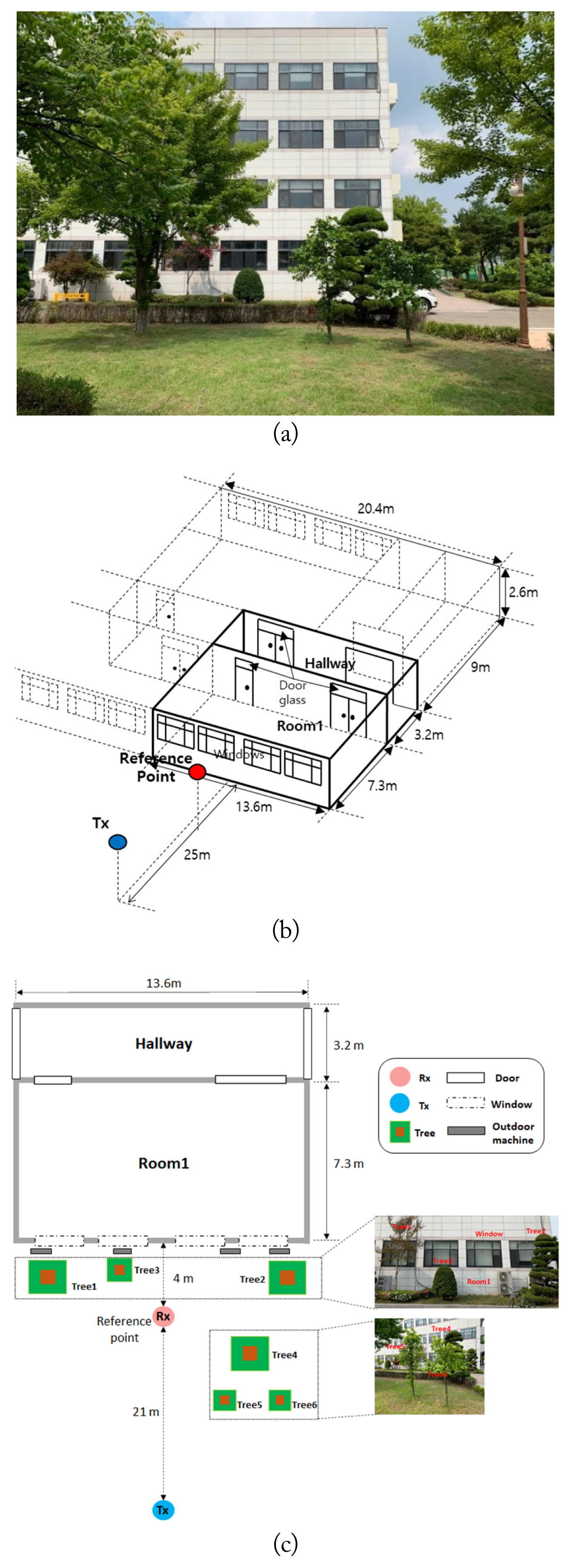
As shown in Fig. 1, the target space for this study is four-story building that has been used in the private sector for over 20 years. Given its age, there is no special structure for shielding electromagnetic waves. The target spaces to be analyzed are located on the first floor and named Room1 and Hallway. The sizes of the target spaces are 13.6 m × 7.3 m × 2.6 m and 13.6 m × 3.2 m × 2.6 m, respectively. Room1 consists of concrete walls, four windows, two different-sized doors, and columns supporting the structure. Hallway consists of concrete walls, several doors, and columns. In addition, there are desks, chairs, and air conditioners inside the target space although this paper does not take these into account.
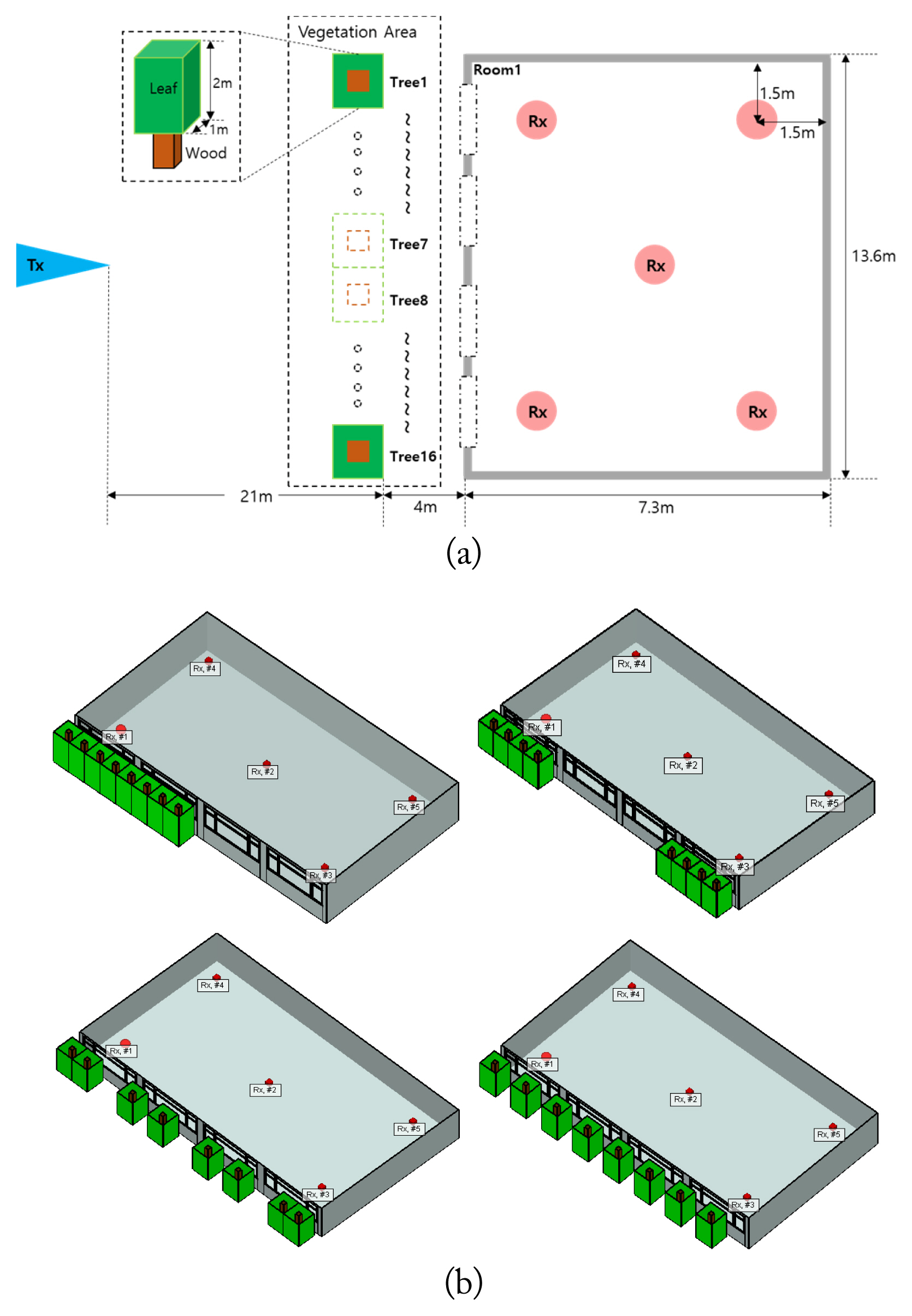
The transmitter is located 25 m away from Room1. From the transmitter, electromagnetic waves are radiated into the target space. The receivers are sequentially located at the points inside the target structure to measure the power level of the electromagnetic waves. As shown in Fig. 1(c), there are various external environmental factors that can affect electromagnetic waves propagating into the target spaces between the transmitter and the receiver. There are many trees of different sizes and types around the target structure, of which six trees form a vegetation area. These are shown in Fig. 2, and their areas are summarized in Table 1.
To analyze the electromagnetic waves within a building, it is important to know the dielectric constant of the building’s wall. However, it is difficult to apply the conventional algorithm to measure the electric properties of a material in a real building wall. Therefore, to obtain information that can be used for the analysis, additional compensations are needed for the results of conventional measurement methods.
In this section, the permittivity of the concrete walls is derived based on the Nicolson-Ross-Weir (NRW) method [18, 19]. Fig. 3 shows the results of verifying the method for measuring the wall through CST simulation [20]. The S-parameter of FR4 is measured in the X-band using WR90 coaxial-to-waveguide adaptor probes. Since the real wall cannot be made to the desired size, it is assumed that the probes are in contact with the wall, as shown in Fig. 3(a). Fig. 3(b) shows the real part of the permittivity derived using the NRW method from the simulated S-parameters. When the thickness is thin, the effect of the error is not large, and when the thickness is sufficiently thick, there is a period in the results. That is, it seems that the real part of the permittivity can be estimated by taking the average of the results of the NRW algorithm.
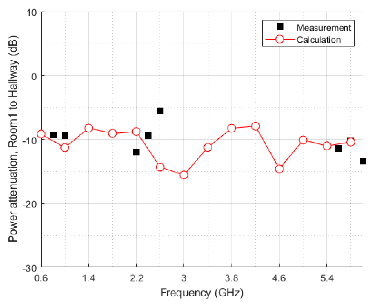
As a result of applying the above method to the S-parameter measurement results for the real wall, it is estimated that the concrete wall of the target structure has a relative permittivity of about 4.44. Since this value its similar to that in the CST simulation tool’s library [20], it is expected that the results of analyzing and simulating electromagnetic waves using this library are sufficiently reasonable. Therefore, the real part of the relative permittivity of the concrete wall is assumed to be 4.4, and the electrical conductivity of the concrete wall is 0.032 S/m. In addition, we calculate the power attenuation from Room1 to Hallway using this permittivity. The calculation method is based on a ray tracing technique, and we set the number of reflections to 1, since convergence properties have been verified through sufficient simulations. First, we calculate the received power under the assumption that all the walls are made of concrete. After this, to consider the real building structure, additional attenuation is applied to the propagating waves based on the ratio of the conductor areas (i.e., doors and columns) to the total wall area. Fig. 4 shows that the calculation results are sufficiently reasonable, compared to the measurement results, and we use the electrical characteristics employed at this time to analyze the propagation characteristics in this paper.
III. Theoretical Approach, Measurement, and Simulation
1. The Theoretical Approach
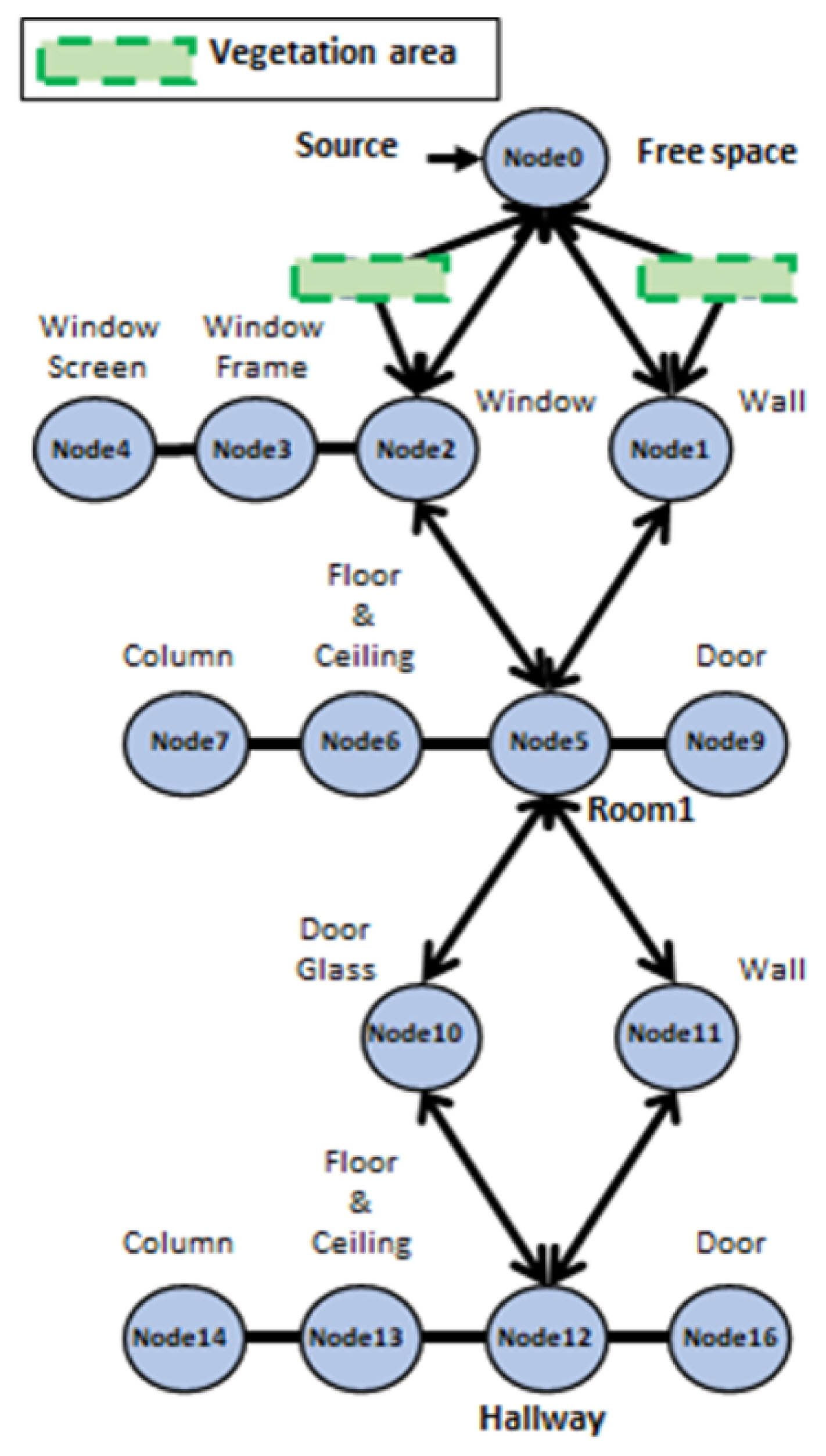
In this paper, the electromagnetic power level is analyzed efficiently using the EMT theory [1] and the PWB method [2–5]. In the EMT theory, large and complex structures are classified into analysis spaces according to their electromagnetic energy level, and the loss factors occurring in the structures are defined. Then, considering the movement or flow of electromagnetic energy, complex large structures are represented by topological diagrams that can easily identify the flow and loss of electromagnetic waves. In the PWB method, it is essential to assume that the magnitude of the electromagnetic waves inside the structure is governed by the law of probability when the electromagnetic environment to be analyzed is considerably larger than the wavelength of the adopted waves. That is, when the size of the structure is electrically large, the electrical field is uniformly distributed at arbitrary points inside the structure, as in a mode-stirred reverberation chamber. In this environment, the total dissipated power occurring inside the structure is the same as the incident power coming from outside, and the loss factors inside the structure can be expressed by scalar quantities as quality factor (Q-factor) and mean coupling cross-section (MCCS). Each loss factor, expressed as a Q-factor or MCCS, depends on the electrical characteristics and geometrical structure. Loss factors that occur inside structures are generally assumed to be caused by walls, antennas, apertures, and objects. The MCCSs and Q-factors of each factor can be calculated by referring to [4, 5]. With reference to this method, the target structure in this paper is represented by the topological diagram shown in Fig. 5.
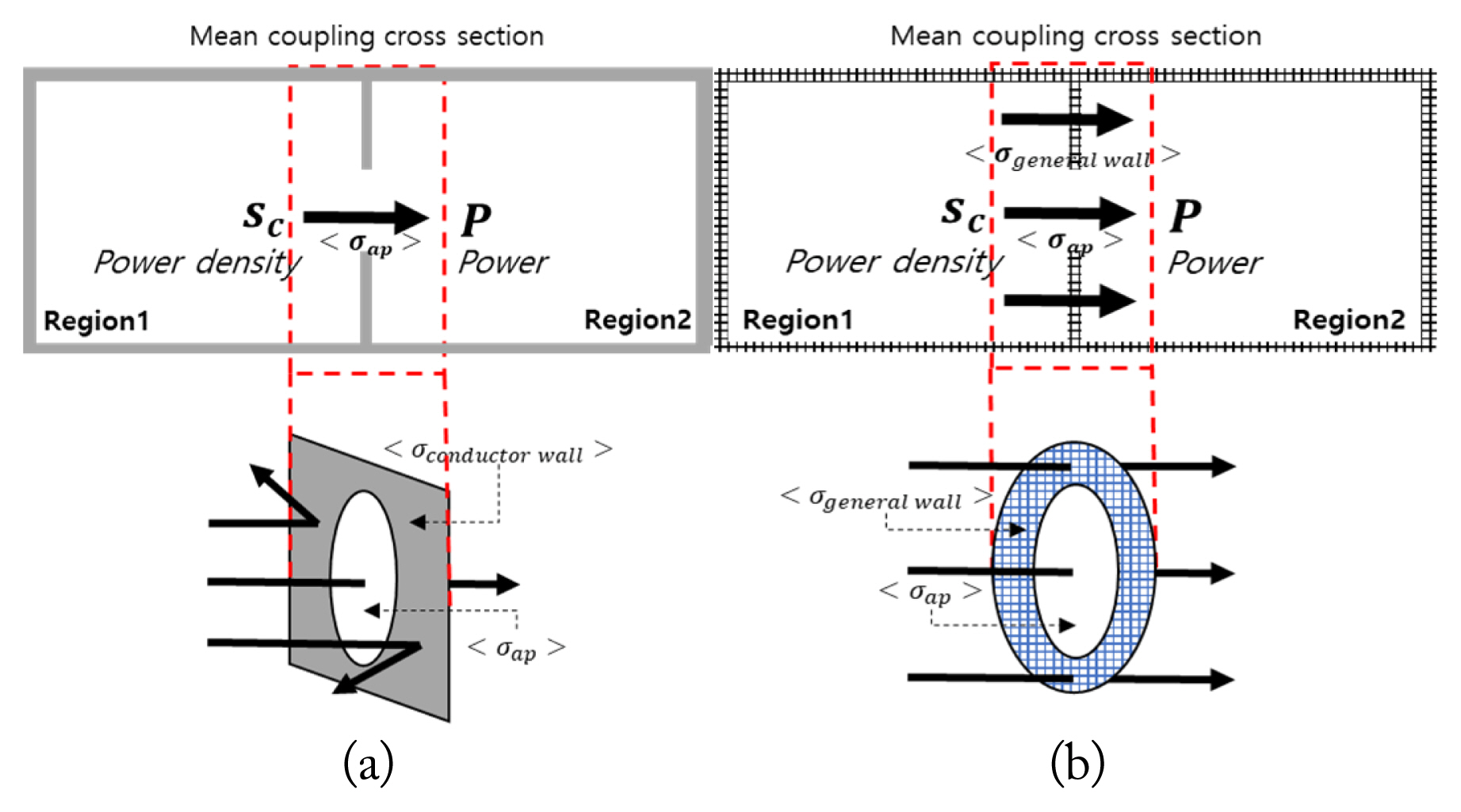
Nevertheless, the conventional PWB method has limitations. The well-known concept of the PWB method is only valid for structures consisting of conductors. In such structures, electromagnetic waves propagate only through apertures, as shown in Fig. 6(a). Therefore, the PEPWB method was proposed to compensate for the limitations of the PWB method [11]. This method replaces Eq. (1), which was used to obtain the MCCS of the wall in the conventional PWB method, with Eq. (2):
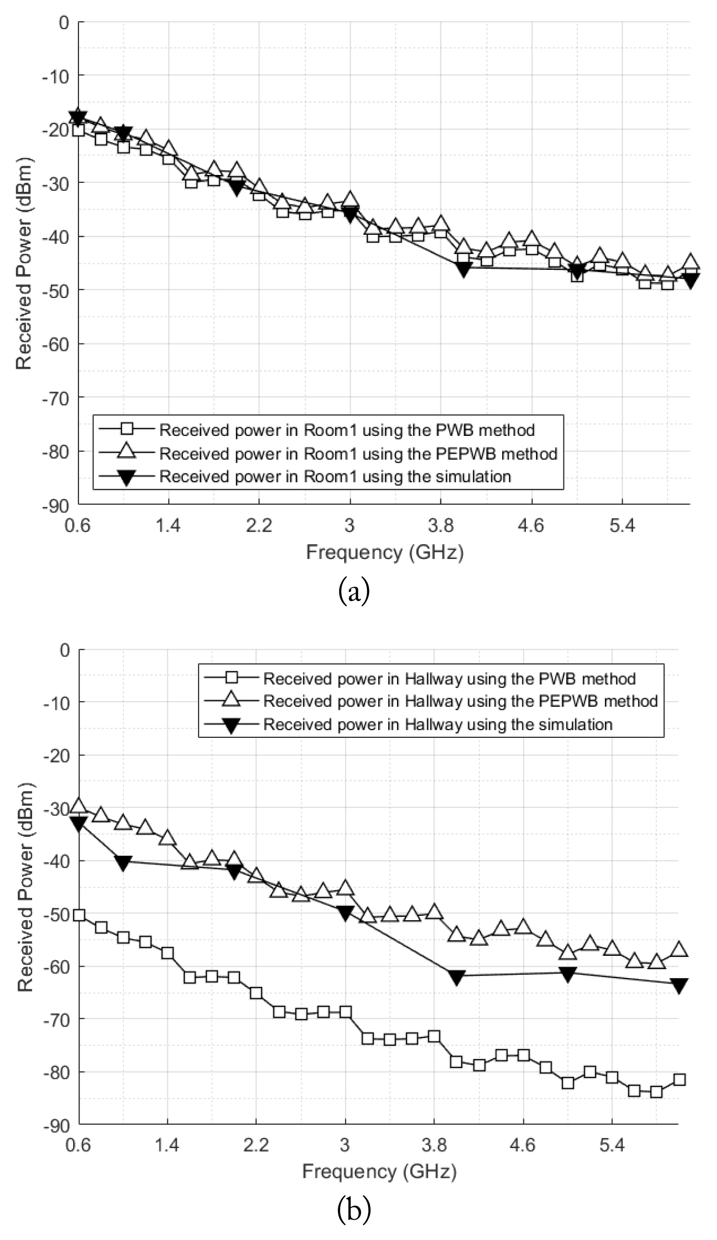
where S is the surface area of the target structure, ur is the relative wall permeability, σ is the wall conductivity, f is the used frequency, awall is the radius of the wall area, Tw is the transmission coefficient of concrete. and c is the speed of light. Tw is determined by the electrical properties of concrete, such as permittivity, permeability, and electrical conductivity, but we deal with it as a dielectric material. This equation was devised by referring to the equation used to calculate the MCCS of the aperture in the PWB method. In the PEPWB method, the electromagnetic waves in a cavity propagate through the apertures and walls that they can penetrate. To express the MCCS of a wall in Eq. (2), the wall seems like an aperture, but it is represented by an aperture with the electrical characteristics of the building material, as shown in Fig. 6(b). Therefore, when using the PEPWB method, the target structure is represented by a topological diagram, as shown in Fig. 7. Also, a two-ray ground reflection model was used to calculate the received power at the reference point and the input power propagating into large structures [21]. The result of this model is affected by the transmitted power, the gain of the antenna used in the measurement, the electrical properties of the ground, the distance between the transmitter and the receiver, the heights of the transmitter and the receiver, and the angle of incidence. The results of the PEPWB and PWB methods inside Room1 and Hallway are shown in Fig. 8 along with the simulation results of Wireless Insite. From Fig. 8, two notable points can be seen. The first is that the results of the PEPWB method have higher received power than those of the PWB method in the two target spaces. The second concerns the difference between the results of the PEPWB method and the PWB method for each of the two target spaces. The reason for the first point is that the PEPWB method, unlike the PWB method, considers electromagnetic waves that penetrate the concrete wall. Therefore, the results of the PEPWB method show higher received power. The reason for the second point can be understood by looking at the structural characteristics of the two target spaces. In the wall between the exterior and Room1, the areas where electromagnetic waves can propagate are the concrete walls and windows. Comparing the areas occupied by the concrete wall and the window in the wall, the area occupied by the window is larger than that occupied by the concrete wall in Room1. That is, when electromagnetic waves propagate into Room1, more electromagnetic waves are expected to propagate through the window because even when considering the electromagnetic waves propagating into the concrete wall, there is no considerable change. However, it is different in the case of Hallway. The wall between the two target spaces consists of concrete walls and columns, steel doors, and glass on the doors. Among the several areas, those where electromagnetic waves can propagate are the concrete wall and the glass door, and the concrete wall occupies more area than the door. Therefore, the difference between the PEPWB method and the PWB method in Hallway is larger than that in Room1.
2. Measurement and Simulation
To verify the accuracy and validity of the theoretical approach, the measurement was carried out and the simulation results were predicted using Wireless Insite. The target frequency range for the measurement is the ISM band between 0.6 and 6 GHz, and the transmitter and the receiver use vertically polarized waves. The transmitting system is located at 25 m from the target space, Room1.
A reference power measurement was performed to precisely identify the received power at the reference point, as shown in Fig. 9(a). The receiver is located 4 m from the target structure and measures the received power. By comparing this result with those of the other measurements, it is possible to grasp the phenomenon of electromagnetic wave attenuation that occurs when the electromagnetic wave propagates from outside to inside the target structure.
The measurement set-up shown in Fig. 9(b) was proposed to evaluate the effect of averaging data from the multiple positions. To consider the directions and locations inside the target spaces, we set the location of the five Rx points to measure the average of the power received inside the target space, as shown in Fig. 9(b), and the four directions (0°, 90°, 180°, 270°) were set based on the direction (0°) in which the receiving antenna faces the transmitting antenna. The measurement was then performed in each location and direction. The results of this method are derived from the mean values of the four directional results at the five receiving points. This measurement circumstance was exploited to simulate the received power of each Rx point by using an electromagnetic simulation tool.
Wireless Insite was used to cross-check the results with the theoretical approach. This tool uses ray-tracing technology and is primarily employed for a wide range of issues of propagation path analysis. Therefore, it is suitable for analyzing the effects of electromagnetic waves on the large-scale structure dealt with in this paper.
To perform an accurate analysis, the target structure and the external environment should be modeled as closely as possible to the real environment. As shown in Fig. 10, a 3D modeling of the target structure was performed using this simulation tool based on the actual physical information of the target structure. The model in Fig. 10(a) is only for the target structure, for which external environment factors were not considered. However, the model in Fig. 10(b) does take into account external environmental factors such as trees. The simulation was performed by setting various parameters close to the actual measurement environment in order to increase the reliability of the cross-check.
IV. Influence of External Environmental Factors on Electromagnetic Wave Propagation
As shown in Figs. 1 and 2, there are various external environmental factors, including trees, between the transmitter and the receiver in the target space. These environment factors can act as a major source of electromagnetic wave attenuation propagating into the target space. However, the influence of these realistic environment factors on radiated electromagnetic waves has, to our knowledge, not yet been clearly explained. Therefore, in this section, we discuss the influence of trees on electromagnetic waves, along with many other external environmental factors.
As shown in Fig. 1(c), when the electromagnetic waves radiated from the Tx point arrive at the target space, they propagate through the concrete walls and windows into the target space. However, if trees are in front of the concrete walls and windows of the target space, this is expected to affect the propagation path of the electromagnetic waves. It is conjectured that the data measured at the receiver inside the target structure, assuming that sufficient time is given, will include electromagnetic attenuation due to the trees. Therefore, taking into account the realistic environmental factors should be considered necessary for an accurate analysis in both the theoretical approach and the simulation.
In the simulation tool, the actual trees can be modeled based on the physical and electrical information, as shown in Fig. 10(b), so that their influence can be taken into account. Because of the simulation tool’s ability to consider both scenarios, (i.e., with and without trees), it is possible to grasp the influence of the trees by comparing the results.
In the theoretical approach using the EMT/PEPWB method, the loss mechanism only considers the loss factors that occur inside the target structure, not outside. The topological diagram shown in Fig. 7 is expressed under this condition. Therefore, a new approach is needed to consider the electromagnetic wave attenuation caused by the external environment factors around the target structure. Based on this concept, we added the effect of vegetation area (trees) to the topological diagram. The updated diagram is shown in Fig. 11. The electromagnetic wave radiating from the Tx point propagates along various paths depending on the structure of the target space and the electrical properties of the structure’s materials. In the target space, the areas where the electromagnetic waves can penetrate the target structure are the concrete walls and windows, as shown in Fig. 12. If the vegetation area is in front of the concrete walls and windows, as in the environment of a normal civil building, it can be expected that the electromagnetic waves propagating into the target structure will be affected by the trees. Therefore, we focused on the area occupied by vegetation. That is, if the electromagnetic effect corresponding to the area occupied by trees in front of the area where electromagnetic wave propagation can be quantitatively estimated and predicted, the tree-scattering effect can be applied to the theoretical approach with more accuracy. To do this, we quantitatively derive the electromagnetic wave attenuation caused by a vegetation area using the simulation tool and apply the results to the theoretical approach to consider the attenuation in this section. The electrical properties of the tree used in this simulation are given in [14].
The simulation environment was designed to quantitatively derive the attenuation of electromagnetic waves caused by the vegetation area, as shown in Fig. 13(a). In this simulation environment, there can be a total of 16 trees in the vegetation area. The area covered by a single tree corresponds to 5% of the concrete walls and windows where electromagnetic waves can penetrate. The simulation is performed by increasing the vegetation area from 0% to 80% of the concrete walls and windows at intervals of 10%. The results for each vegetation area are derived by averaging the simulation results of cases where trees can be located. For example, there are eight trees covering 40% of the concrete wall and window in front of the target structure, as shown in Fig. 13(b). By subtracting the result without the trees (vegetation area 0%) and the other results (from 10% to 80%), the electromagnetic wave attenuation caused by each vegetation area can be derived. Based on the method mentioned above, the attenuation due to the vegetation is shown in Fig. 14. As expected, the greatest attenuation of the electromagnetic wave occurs when the trees occupy the largest area. If these results are considered in the EMT/PEPWB method, more accurate results can be obtained because both the attenuation occurring inside the target structure and that caused by the external environment can be considered simultaneously.
V. Results and Discussion
As shown in Figs. 1 and 2, because there are many trees between the transmitter and the receiver in the real environment, it can be expected that the attenuation caused by the trees plays an important role in the penetration of wave into the building. To consider the actual environment, the area of the concrete walls and windows in the target space and the area of the trees in the actual environment are considered as shown in Figs. 2, 12, and 13. The occupying areas of the concrete walls and windows are 37.6 m2, and the total area of the trees is 27.91 m2. The actual sizes of the trees are listed in Table 1. Comparing the area of the concrete walls and windows with the area of six trees, the trees occupy about 70% of the area that can be penetrated by the electromagnetic waves. Therefore, the resulting vegetation area of 70% shown in Fig. 14 is coupled with that of the theoretical approach.
The first step is to compare the results of the measurement, simulation, and two-ray ground reflection model at the reference point. The received power simulation environment at the reference point considering the vegetation area is shown in Fig. 10(b). In Fig. 15, the results of the measurements and the simulations are compared with those of the theoretical approach. Since all results have a similar tendency, as shown in Fig. 15, it can be seen that the two-ray ground reflection model used as the source of the theoretical approach is reliable. Also, the results of the simulation with vegetation areas are slightly different from those of the simulation without vegetation areas. This result is due to the physical phenomena of electromagnetic waves, such as the reflections and diffractions caused by the presence of vegetation areas.
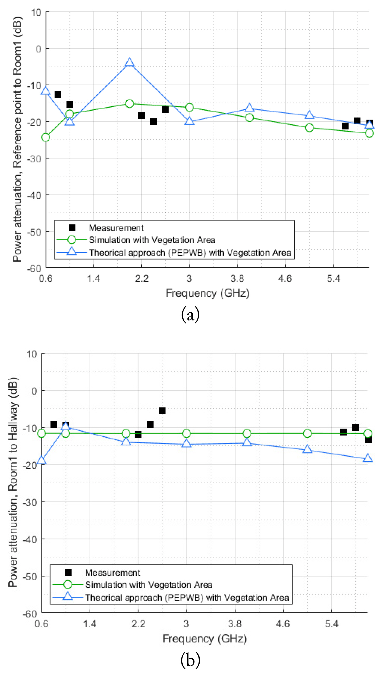
In Fig. 16, the results of the measurement, the simulation, and the theoretical approach are compared in line with the influence of vegetation areas in terms of the power attenuation from the reference point to Room1 and from Room1 to Hallway. These results show a similar tendency, as shown in Fig. 16(a). If this influence is not considered, the theoretical and simulation results will have lower attenuation than the measured results. Fig. 16(b) also shows this conclusion. However, since both the received power in Room1 Hallway is affected by the vegetation area, the power attenuation from Room1 to Hallway is less affected by it. In this case, the effect of the concrete walls is thought to be significant. Consequently, various external environmental factors surrounding the target structure, as well as the loss occurring inside the structure, should be considered in order to accurately ascertain the extent of electromagnetic wave propagation from the outside to the inside of the target structure.
The algorithm of the theoretical approach was written in MATLAB code developed by our own program, and the time taken by the algorithm was recorded as approximately 10 seconds. However, Wireless Insite required more than 25 hours to simulate four receiving antenna directions to obtain conditions similar to those of the measurement set-up described in Fig. 9(b).
VI. Conclusion
This paper analyzed the received power level of electromagnetic waves propagating efficiently and accurately from an external source into complex and large structures using a theoretical approach with relatively low time consumption. To this end, the EMT/PEPWB method, which can efficiently consider the characteristics of large and complex structures, was used as the theoretical approach in this paper. To verify the accuracy and effectiveness of the proposed theoretical approach, measurements were performed in a large and complex structure. In addition, the results of a simulation using Wireless Insite were used for validation.
We also investigated the influence of an external environment factor, a vegetation area, on the electromagnetic wave propagation into the target structure using the simulation tool. To derive quantitative values of the attenuation caused by vegetation areas in the external environment of the target structure, we focused on the area occupied by the trees between the transmitter and the receiver. The vegetation attenuation was then quantitatively considered in conjunction with the EMT/PEPWB method. Following this, the accuracy of the theoretical approach was confirmed by comparing the measurement and simulation results.
The theoretical model proposed in this paper should select the appropriate vegetation attenuation and have limited accuracy in lower frequency bands. However, if the influence of the electromagnetic wave attenuation caused by an external environmental factor were quantitatively derived, the theoretical approach using our own program will be expected to be more efficient and practical than the commercially available simulation tool. In addition, the accurately identified characteristics of radio wave propagation into the interior of the building can be used to analyze the three-dimensional shielding effectiveness of building structures in the future.