I. Introduction
Recently, Internet of Things (IoT) technology, which connects all objects to the internet and controls various information from objects, has progressed with 5G technology, which enables high-speed internet connectivity. As the number of various IoT devices is increasing rapidly, the use of technology to classify and track various IoT devices has become more important. A radiofrequency identification (RFID) tag can be a simple solution in IoT technology to help identify and locate objects without batteries in a way that reflects a transmitted signal with its information [1]. However, it is vulnerable to interference and noise from the surrounding environment because of the received weak signal reflected by an RFID tag with a relatively small scattering cross-section [2].
A harmonic transponding-based RFID tag, which receives fundamental waves and reflects harmonics generated by nonlinear electronic elements, including diodes, transistors, and field-effect transistors (FETs), is an alternative approach to enhancing the signal-to-noise ratio [3]. The harmonic transponder comprises a diode and an input and output matching network. The configuration method of the harmonic transponder is classified into a reflection type, whose input and output terminals are combined [4, 5], and a through type, whose input and output terminals are separated [3, 6ŌĆō10]. By implementing each matching network, the through-type harmonic transponder can easily match the input impedance to the source at the fundamental frequency, and the output impedance to the load at the harmonic frequency. However, it is unsuitable for compact RFID tags because it may require two antennas and both input and output matching networks. In [11], a diplexer-based harmonic transponder can provide high isolation between Tx and Rx antennas, even with only one antenna. However, in addition to requiring an additional diplexer design, the bandwidth of the harmonic transponder can be narrowed by the diplexer.
In this study, we propose a reflection-type harmonic transponder for battery-less RFID sensors. The proposed circuit comprises a dual-band matching network (DBMN) and a diode for harmonic backscattering. It is possible to implement a harmonic transponder with low insertion loss and a small size with only the DBMN to match the load at the fundamental and harmonic frequencies simultaneously. The proposed circuit is implemented in an ultra-small size of 19 mm ├Ś 17.8 mm. As a result of the measurement, a conversion gain (CG) of over ŌłÆ10 dB is maintained in the input power range of ŌłÆ6.4 to 10.6 dBm at 2.45 GHz. The proposed harmonic transponding-based RFID tag with a chip antenna can be detected from a distance of 6.3 m with a transmitted equivalent isotropic radiated power (EIRP) of 42.6 dBm.
II. Harmonic Transponder Design
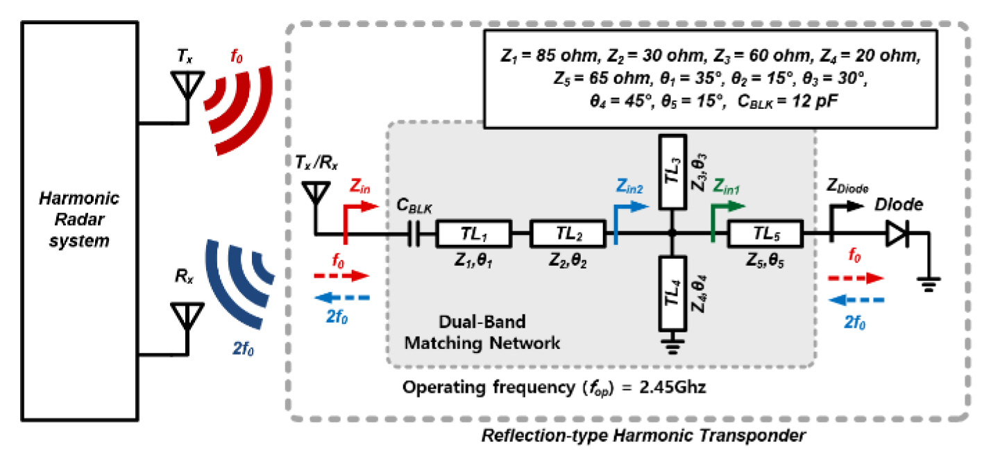
As one of the methods to configure the harmonic transponder, the number of elements, including antennas and matching networks, in the reflection-type harmonic transponder can be decreased; however, but the DBMN is required to have a high second harmonic exciting response of the harmonic transponder with low insertion loss [12, 13]. In this design, we introduce a low-loss reflection-type harmonic transponder with a transmission-line based DBMN, as shown in Fig. 1. A transmission line-based matching network has a large impedance change according to frequency and can accurately predict the input impedance of the matching network using electromagnetic (EM) simulation compared to a lumped element-based matching network with a tolerance of about 5%ŌĆō10% [14]. Thus, it is suitable for composing a network that matches the load at the desired fundamental and harmonic frequencies.
Fig. 2 shows the simulated input and output impedance of the proposed harmonic transponder with different input power levels at the target fundamental frequency of 2.45 GHz and the second harmonic frequency of 4.9 GHz. A series transmission line, TL5, is the interconnection line between a harmonic generating diode and the DBMN. A shorted stub TL4 parallel to the diode acts as both a DC feed (0 V) and the matching network at the fundamental frequency without affecting the input impedance at the second harmonic frequencies, as the electrical length of TL4 is set to ╬╗/4 at 4.9 GHz. As depicted in Fig. 2(a) and 2(b), the width of TL4 and the length and width of an open stub TL3 are optimized to shift the input impedance ZD close to the voltage standing wave ratio (VSWR) = 2 circle at 2.45 GHz and 4.9 GHz. Series transmission lines TL1 and TL2 are set to change the input impedance Zin at 4.9 GHz adjacent to the VSWR = 2 circle, whereas Zin at 2.45 GHz remains almost unchanged.
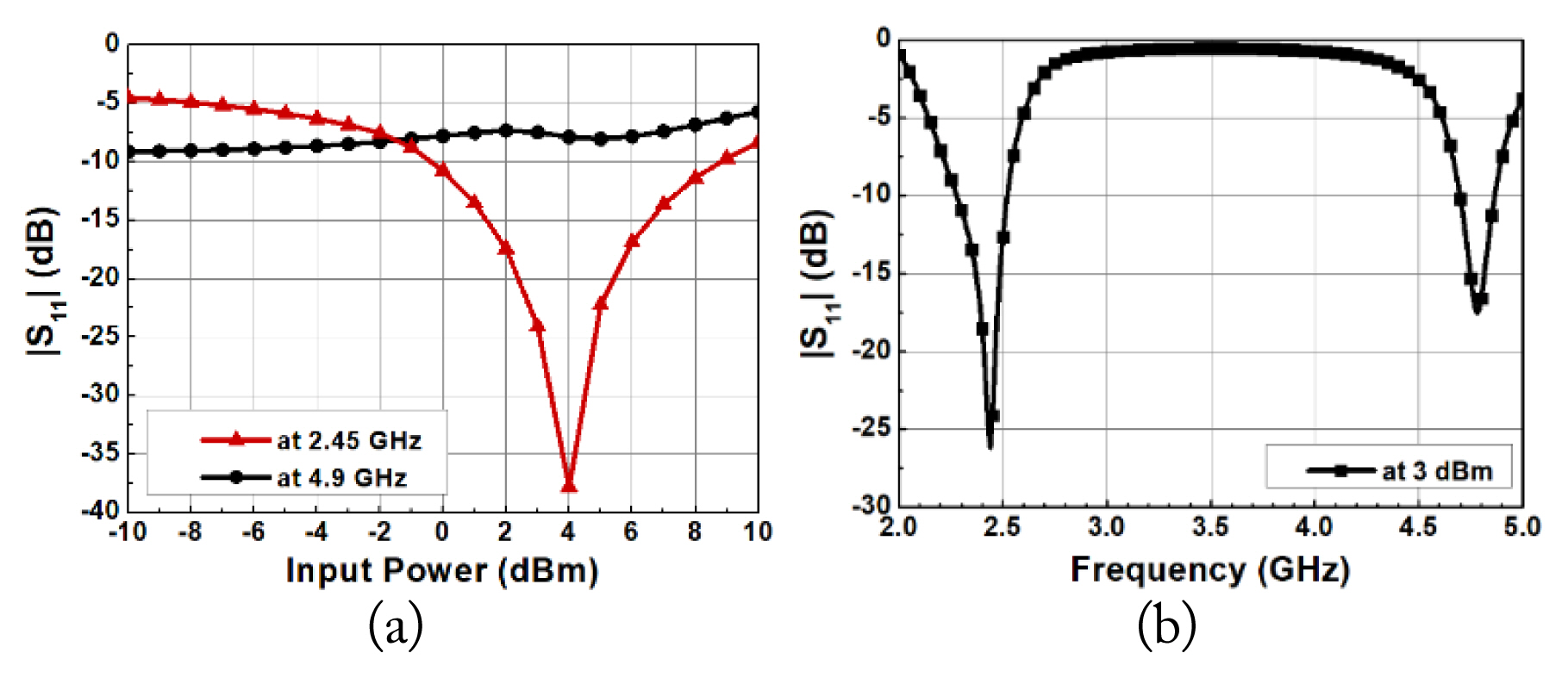
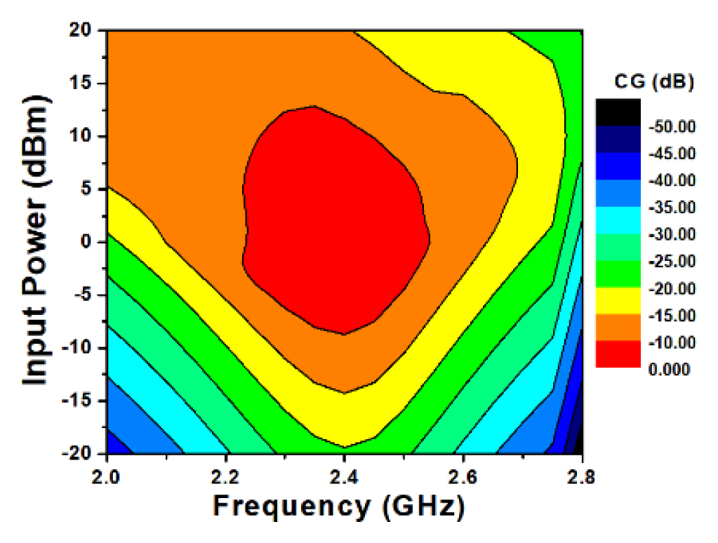
Fig. 3(a) presents the simulated input return loss |S11| of the proposed harmonic transponder at 2.45 GHz and GHz with different input power levels. |S11| is under ŌłÆ10 dB in the input power range of ŌłÆ0.3 to 8.8 dBm at 2.45 GHz and under ŌłÆ5 dB in the input power range of ŌłÆ10 to 10 dBm at 4.9 GHz. As shown in Fig. 3(b), |S11| is under ŌłÆ10 dB in the fundamental and second harmonic bands of 2.28ŌĆō2.52 GHz and 4.7ŌĆō4.86 GHz. The simulated CG of the proposed harmonic transponder with different frequencies and input power levels is obtained, as shown in Fig. 4. The proposed circuit obtains a high CG of over ŌłÆ10 dB in the wide input power range of ŌłÆ4 to 7 dBm when the operating frequency varies from 2.25 GHz to 2.5 GHz, as the diode of the harmonic transponder matches the load well at the fundamental and second harmonic frequencies within a wide input power range.
III. Implementation and Experimental Evaluation
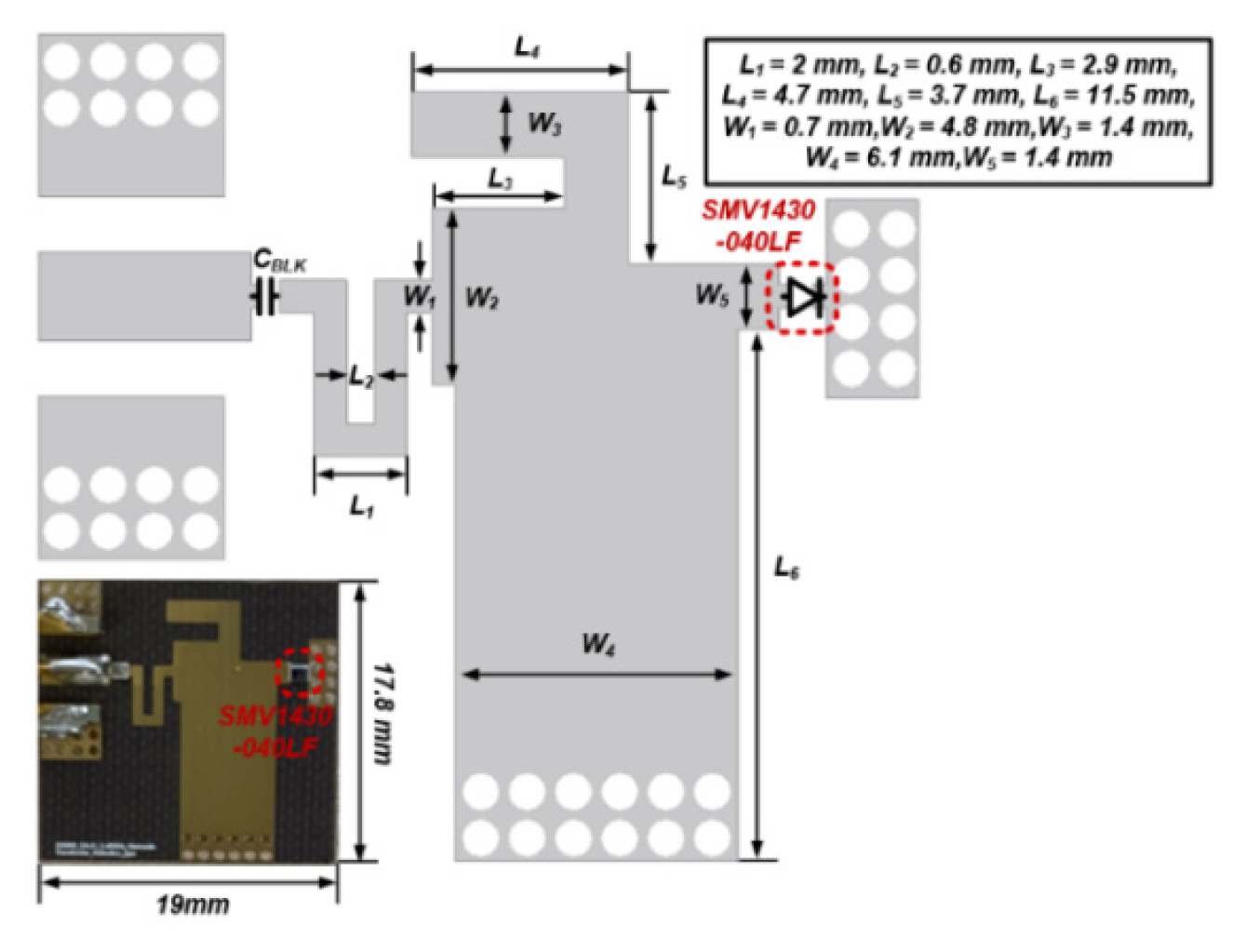
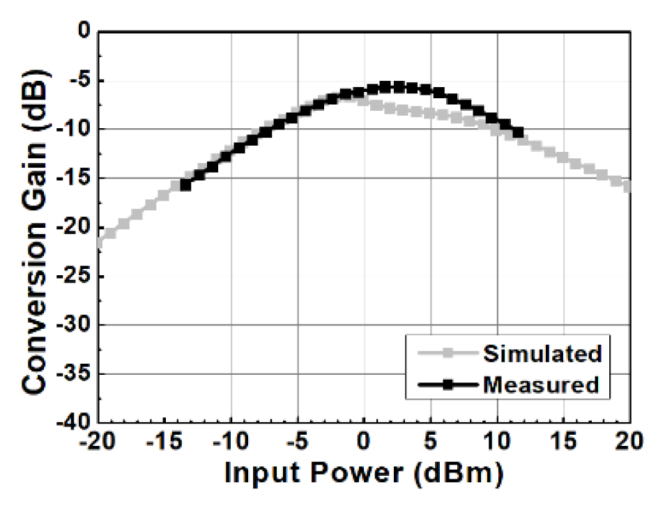
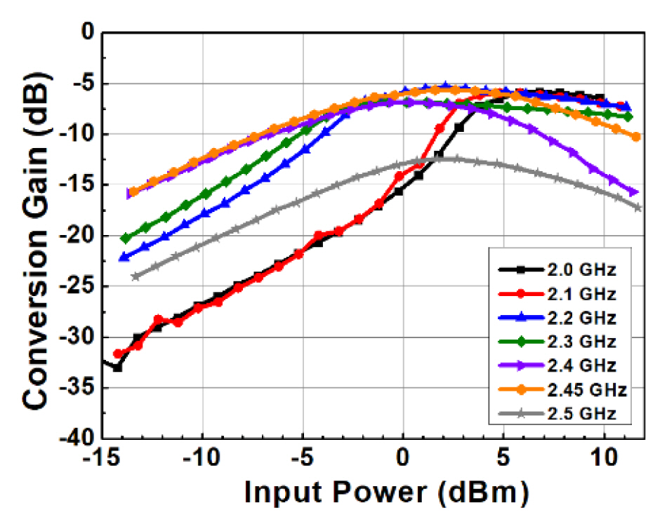
As illustrated in Fig. 5, the proposed harmonic transponder was fabricated using TaconicŌĆÖs TLC-32 substrate (dielectric constant = 3.2, loss tangent = 0.003, thickness = 0.813 mm). The Skyworks SMV-1430-040LF diode varactor was used as a nonlinear element. The input and output DC blocking capacitors were adopted at 12 pF. The circuit was optimized via harmonic balance, a large signal S-parameter, and an EM simulator based on the Advanced Design System. To verify the implemented harmonic responder, a second harmonic output power and a CG were measured using a Keysight E8247C signal generator and a Keysight E4407B spectrum analyzer. As shown in Fig. 6, the proposed harmonic transponder achieved a peak CG of ŌłÆ6.5 dB and maintained a CG of above ŌłÆ10 dB in the wide input power range of ŌłÆ6.4 to 10.6 dBm at 2.45 GHz. Fig. 7 shows the measured CG with frequency and input power. It remained above ŌłÆ10 dB in the 2.2ŌĆō2.45 GHz frequency band, as the input power level varied from ŌłÆ3.9 to 6.4 dBm. The peak CG from ŌłÆ5.3 to ŌłÆ7.5 dB was obtained in the frequency range of 2.0ŌĆō2.45 GHz at an input power of 3.1 dBm.
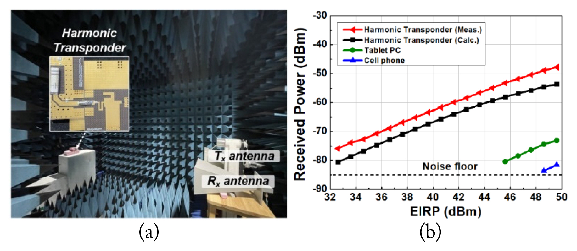
To check whether the proposed harmonic transponder is detectable from a long distance, the circuit consisted of a W3006 chip antenna (Pulse Electronics, San Diego, CA, USA), and the measurement environment was set up in a radio anechoic chamber, as shown in Fig. 8(a) [15]. The W3006 chip antenna had a gain of 2.0 dBi at 2.45 GHz, and the extrapolated gain value at 4.9 GHz was about 3.0 dBi. The fundamental signal was produced by a Keysight E8247C signal generator, an OPHIR5183 power amplifier (Test Equipment Connection Corp., Lake Mary, FL, USA), and an LFCN-3400 low-pass filter (Mini-Circuits, Brooklyn, NY, USA). A BBHA-9120-LF horn antenna (Schwarzbeck, Schonau, Germany), as a transmit antenna, was connected to the low-pass filter. The second harmonic signal was received using a Keysight E4407B spectrum analyzer with a VT58SGAH20NK horn antenna (Vector Telecom, Melbourne, Australia). In the measurement setup, the distance between the target and the Tx and Rx antennas was 2.3 m.
Fig. 8(b) shows the calculated and measured second harmonic signals of the proposed harmonic transponder and various electronic devices. The output power received was calculated using the Friis transmission equation in [11]. The second harmonic power received from the harmonic transponder was at least 23.7 dB greater than that from the electronic devices at 49.6 dBm of the EIRP. The difference between the calculation and measurement results was caused by the difference in CG according to the input power and the inaccuracy of the antenna model.
As illustrated in Fig. 9(a), the harmonic transponder was also measured with the same equipment in the building corridor to obtain the maximum detectable distance. Fig. 9(b) shows the measured harmonic response of the proposed harmonic transponder at 42.6 dBm of the EIRP. The maximum detectable range was 6.3 m because of the limited corridor length. The difference between the calculation and measurement results was due to the reflection signals from the wall and the ground.
Table 1 presents the performance comparisons of the proposed harmonic transponder to previous works. It shows that the proposed circuit has one of the highest CGs and the widest dynamic input power range and the smallest size.
IV. Conclusion
This study presented a novel harmonic transponder and verified the feasibility of the proposed circuit as an RFID sensor. The reflection-type harmonic transponder that can be shared between the input and output terminals considered a DBMN to reduce the insertion loss in the wide input power range, minimizing the circuit size. The proposed harmonic transponder achieved a high CG of over ŌłÆ10 dB in the input power range of 6.4ŌĆō10.6 dBm at 2.45 GHz and in the frequency range of 2ŌĆō3 GHz at an input power of 13 dBm. The maximum detectable range of the proposed harmonic transponding-based RFID tag consisted of a 6.3 m chip antenna when the transmitted EIRP of the signal generator with a horn antenna was 42.6 dBm.