Compact Asymmetrical Quasi-MMIC Doherty Power Amplifier
Article information
Abstract
This paper presents a compact asymmetrical Doherty power amplifier (PA) based on a quasi-MMIC configuration for 5G sub-6 GHz applications. The proposed Doherty PA is composed of commercial GaN HEMTs and several passive components implemented on a silicon (Si) substrate. In order to achieve size and cost advantages, passive components such as a power divider, input matching networks, output matching networks, and a Doherty combiner are realized using Si-integrated passive device (Si-IPD) technology, which costs about 40% of the budget for the entire GaN MMIC process. For the 3.5 GHz pulsed-continuous waveform signal, the fabricated Doherty PA has an efficiency of 52.6% at a saturated output power of 44.2 dBm. Furthermore, an efficiency of 45.6% was achieved with the output power back-off (OBO) of 7.0 dB. The implemented PA occupies only 8.9 mm × 5.6 mm.
I. Introduction
As array-based communication systems evolve, the number of power amplifiers applied to the system has increased; thus, the miniaturization of amplifiers has become an important issue [1–3]. Furthermore, power amplifiers (PAs) such as envelope tracking, Chireix, and Doherty PAs are being heavily studied because of their ability to support high-efficiency and high peak-to-average power ratio (PAPR) specifications. Specifically, Doherty PA is being focused on its simple structure, broad bandwidth, and easily extendable dynamic range. N-way Doherty PA is a traditional method for obtaining an extended dynamic range. In addition, asymmetrical Doherty PA can provide a wide dynamic range by using asymmetrical two-power cells or an uneven power divider [4]. These power amplifiers can be implemented with a simple and small structure to be a suitable solution for 5G small cells. Meanwhile, most compact high-power amplifiers have been implemented with the gallium nitride (GaN) monolithic microwave integrated circuit (MMIC) process because of the high breakdown voltage and superior performance up to mmWave frequency. However, due to the high manufacturing cost of GaN MMIC, developing a cost-reduction technology has become an urgent issue. In this respect, a quasi-MMIC technology consisting of bare-die-type power cells and integrated passive devices (IPDs) might be a suitable solution due to its reduced size and fabrication cost. So far, the literature has explored Doherty PA based on quasi-MMIC with acceptable performances [5, 6].
One of these papers used dual input to optimize performance [5]. Another article proposed the Doherty PA with an external power divider with large dimensions [6]. Therefore, it is difficult to estimate the circuit size of these results; thus, further process optimization efforts are needed to implement the complete quasi-MMIC Doherty PA architecture. To achieve a compact and high-performance Doherty architecture, we designed and implemented the asymmetrical Doherty PA based on quasi-MMIC technology.
II. Proposed Doherty PA Design and Fabrication
Generally, Doherty PAs take Class-C bias as the peaking amplifier for good hold-off operation. However, when a peaking amplifier’s power cell has the same size as a power device of the carrier amplifier, the Doherty PA has been shown to exhibit a limited dynamic range of less than 6 dB. A rough analysis reveals that the peaking amplifier’s maximum drain current is half that of the carrier amplifier, thus limiting the dynamic range of the Doherty PA. The solution to this problem is to use a large power cell of the peaking amplifier so that it has the same peak current for each amplifier. Furthermore, assuming that the peak current of the peaking amplifier is greater than that of the carrier amplifier (i.e., when designed more than twice as large), the Doherty PA has an extended back-off point of more than 6 dB. In other words, the dynamic range of the Doherty PA can be defined by the division ratio of the peak drain currents (S). The related equations are as follows:
Fig. 1 shows a schematic of the designed asymmetrical Doherty PA. The proposed Doherty PA consists of six IPDs, and different two GaN-HEMTs (CG2H80015D, CGH60030D). Fig. 2 shows a simulated characteristic in which the peak drain current of the peaking amplifier is higher than that of the carrier amplifier. After calculating this result by applying Eq. (2), the back-off point was confirmed to be 7.43 dB. The IPDs used included a Wilkinson power divider with a Tee-network phase shifter, matching networks, and a Doherty combiner. The phase shifter compensated for the phase imbalance created by the Doherty combiner and each amplifier. The amplifiers were designed based on a 2f0 LC-resonator in the input matching network (IMN) for high-efficiency performance by shorting the 2nd harmonic of an input signal. Fig. 3 shows the simulated results of the carrier amplifier with and without a resonator. The Igs waveform was rectified close to a half sine wave through 2f0 impedance control, as shown in Fig. 3(a). Therefore, high efficiency can be achieved by reducing DC power consumption while retaining similar gain and output power characteristics, as shown in Fig. 3(b). The output matching networks were designed to adopt an LC ladder structure with interconnecting drain wires and a shunt capacitor. The Doherty combiner consists of an impedance inverter and an optimal offset phase shifter with a π-network architecture applied. The phase shifter was designed to ensure that the peaking amplifier’s output impedance becomes infinite. The reduction of the designed Doherty PA to a compact size was attempted by merging several shunt capacitors placed on a common node. The implemented Doherty PA is shown in Fig. 4 and occupies an area of only 8.9 mm × 5.6 mm.
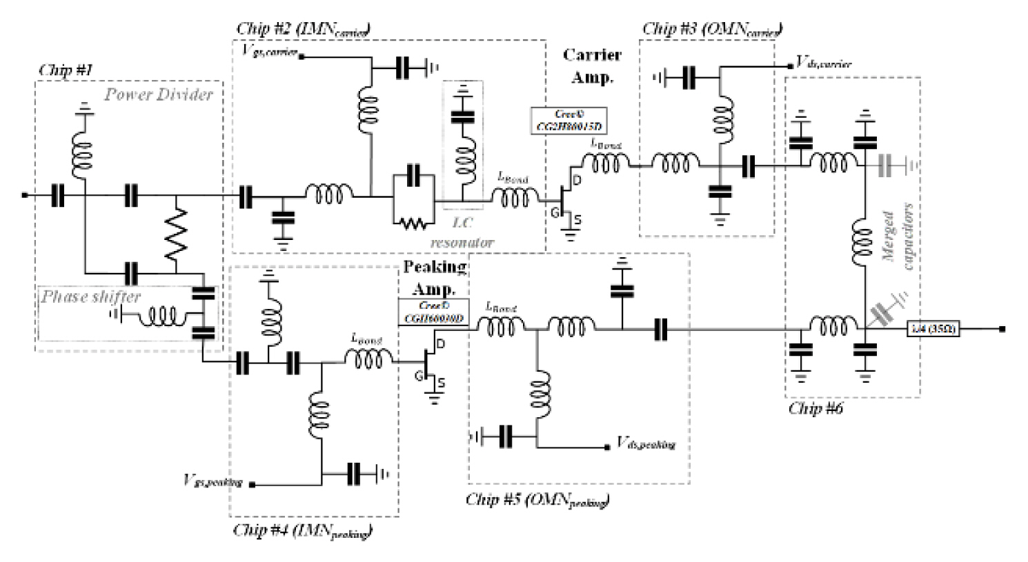
Schematic of proposed Doherty power amplifier.

IDS of carrier and peaking amplifiers versus the output power of the designed asymmetrical Doherty power amplifier at 3.5 GHz.

Simulated results of the carrier amplifier with and without the 2nd resonator: (a) Igs waveforms and (b) large-signal response.

Photograph (a) and layout (b) of the designed Doherty power amplifier.
When estimated through the cost of Wolfspeed’s GaN MMIC process and the GaN HEMTs used to implement the proposed circuit, the cost of Onsemi’s IPD process, and the size of Qorvo’s GaN MMIC PA with similar specifications to the proposed PA, the quasi-MMIC DPA has been confirmed to reduce unit cost by more than 60%.
III. Measurement Results and Verification
The implemented Doherty PA was measured under the following conditions: the carrier amplifier was measured in Class–AB with Vds = 30 V, and the peaking amplifier was measured in deep Class-C with Vds = 35 V. Fig. 5 shows the measured and simulated small and large-signal responses of the Doherty PA, respectively.

Simulated (solid and dash lines) and measured (symbols) responses of the proposed Doherty power amplifier: (a) small signal response and (b) large signal response at 3.5 GHz.
The small-signal gains of the Doherty PA were 9.1 dB, and the return loss was 12.5 dB. The fabricated Doherty PA under pulsed-continuous waveform (CW) input signals with a 3.5 GHz fundamental component exhibited a drain efficiency of 52.6% at a saturated output power of 44.2 dBm, and the DE was 45.6% at 7 dB output power back-off (OBO). The power gain is dropped at the OBO region because of the peaking amplifier’s bias condition (Class-C) tradeoff between efficiency and power gain. It is significant to note that these measured results were in good agreement with the expected and simulated performance. Table 1 compares the performance of the proposed Doherty PA, which shows excellent power and efficiency with fully integrated passive IPDs [5–9].

Comparison with published sub 6 GHz Doherty power amplifiers
IV. Conclusion
This paper implemented an asymmetric Doherty PA based on quasi-MMIC technology with fully integrated passive components. The Doherty PA had a saturation output power of 26.5 W and an efficiency of 52.6% at 3.5 GHz while occupying less than 50 mm2. In particular, since the circuit was composed entirely of passive components, the fabrication cost can be lowered by 40% compared to the commercial GaN MMIC process while maintaining comparable performance.
Acknowledgments
This work was supported by the R&D program funded by MSIT/IITP (No. 2018-0-00753) and the Global R&D program of MOTIE/KIAT, Republic of Korea (No. P127600004).