I. Introduction
Trapped ion technology has become one of the most exciting fields recent years as it results in a number of cutting-edge research areas and technologies, for example, fundamental physics experiments to investigate atomic or molecular properties [1, 2], chemical mass analyzer mass spectrometry to determine, with high precision, the molecular weights of complex compounds [3–5], and a building block of isolated ion to serve as a qubit in trapped ion quantum computer technology [6–9]. These inventions and technologies introduce a number of emerging industrial sectors that accelerate and deliver enormous impacts on communities worldwide.
Samuel Earnshaw first investigated the stability issue to control a charged particle in free space in an electrostatic field [10]. His study has laid the foundation and paved the direction for current ion trap techniques. So far, there have been two most common types, namely Paul trap and Penning trap techniques. The former technique [11–13] was first introduced by Paul [14]; it employs dynamic electric fields to trap a charged particle by creating an average confining force in all three directions that change over time. The latter technique [15, 16] was proposed by Han Georg Dehmelt, inspired by Penning’s vacuum gauge invention. It is noteworthy that this specific schematic differs from the Paul trap technique by adopting an electrostatic field, instead of a time-varying electric field, accompanied by a uniform magnetic field to confine an ion particle.
Despite some researches dedicated to studying several applications employing Paul and Penning trap techniques [17–20], the works that have investigated, in rigorous detail, the possibility to confine an ion particle in a non-uniform electrostatic field remain limited. Still skeptical, we believe that there should be a prospect to confine an ion particle in free space using an electrostatic field [21, 22], but its spatial distribution should be under non-uniform conditions. Therefore, in this study, our objective is to attempt to prove and affirm that idea through in silico investigation, based on the developed mathematical model of the equation of motion of an ion particle in a non-uniform electrostatic field induced by two ionic rings with a common centerline. A one-dimensional model is employed in this work to conveniently obtain and readily verify our proposition. To develop the equation of motion, we first establish the electrostatic field model generated by each ring using the multipole-expansion technique under the azimuthally symmetrical charge distribution assumption [23–25], rather than using a boundary condition approach found in Jackson’s study [26]. Then, we apply the superposition principle to determine the total electrostatic field generated by both rings, and the equation of motion is finally obtained based on the Lagrangian mechanics’ framework [27, 28]. It is important to note that the total electrostatic field is expressed in the quadratic potential function, of which Legendre polynomials [29] in the series expansion are addressed up to order n = 2, where the higher-order terms after n = 3 are truncated due to the small amplitude of oscillation assumption.
II. Electrostatic Theory
1. Method for an Electrostatic Potential Function
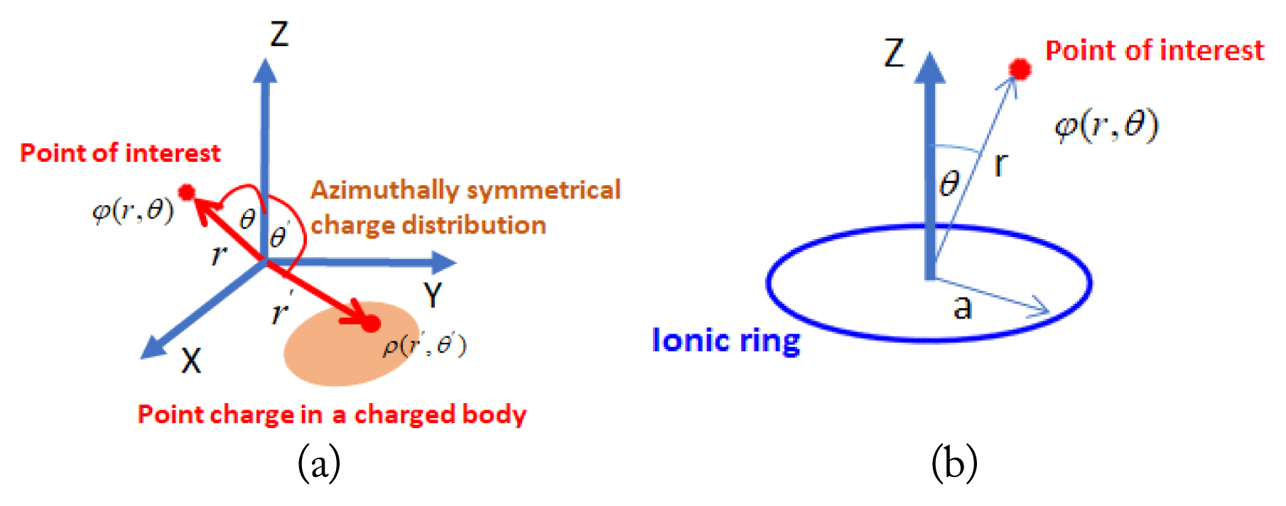
To find an electrostatic potential function generated by an azimuthally symmetrical charge distribution in a free region, as shown in Fig. 1(a), the multipole expansion method [23–25] is employed to determine the form of electrostatic. We recall the potential charge distribution in integral form as Eq. (1):
where ϕ(r, θ) denotes the electrostatic potential function created by the volumetric charge density distribution function ρ(r′, θ′), r and θ respectively signify a radial distance and an inclination angle in the polar spherical coordinate at the location under consideration, while r′ and θ′, respectively represent a radial distance and an inclination angle in the polar spherical coordinate (pointing to the location of a charge distribution), and dv′ denotes the infinitesimal volumetric body of a charge distribution. To express 1/||r-r′|| in the algebraic form to facilitate the upcoming derivation process the definition of the vector norm is employed.
Next, we specify that r > represents the maximum magnitude between ||r|| and ||r′||, whereas r < denotes the minimum magnitude between these two variables, namely r > = max (||r||,||r′||) and r < = min (||r||,||r′||). Therefore, Eq. (2) can be rewritten, as shown in Eq. (3):
Obviously, r < is less than r >; in other words, r < / r > is literally less than unity; r </r > < 1, which leads to (r < / r >)2 – 2(r. r′)/(r >)2 and is also less than unity, according to the binomial series expansion definition, can be rewritten, as shown in Eq. (4):
It is important to note that if the r < r′ condition is satisfied, the potential field relation provided by Eq. (4) is finally obtained under an azimuthally symmetrical charge distribution speculation [23–25]. This can be expressed by an integral form, as shown in Eq. (5):
Note that ϕ(r, θ) represents the electrostatic potential generated by a distributed charge at r and θ coordinate, pn(cosθ) is a Legendre polynomial of order n as a function of cos θ parameter, ρ(r′, θ′) denotes a density function of azimuthally symmetrical charge distribution r′and θ′coordinate, pn(cosθ′) is a Legendre polynomial of order n [29] corresponding to cosθ′parameter, and v′ signifies the volume of an azimuthally symmetrical charge distribution. The numerical orders of the Legendre polynomial function are provided in Table 1.
2. Determination of Electrostatic Potential Function
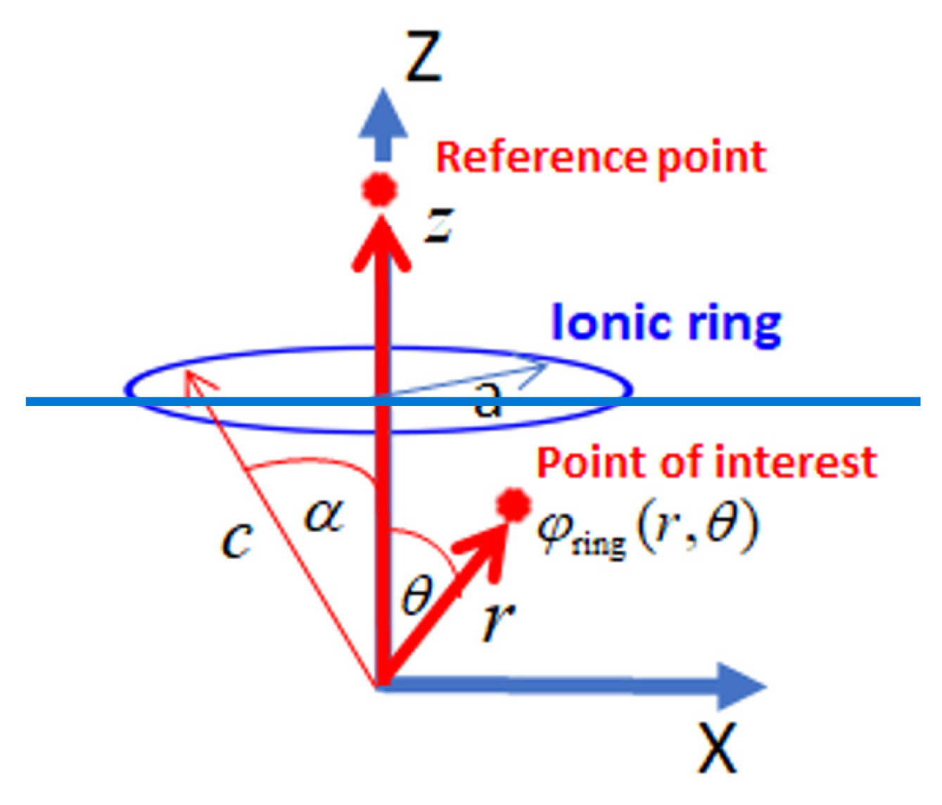
In this section, we demonstrate how the electric potential function of a single ionic ring, illustrated in Fig. 2, is developed using Eq. (5).
According to the system configuration, the ionic ring center is located above the origin in the z-axis direction, where the position under consideration at radial distance r is confined within the c value to ascertain that the r < r′ condition has been met. The azimuthally symmetrical charge distribution density function of a single ionic ring, per Fig. 2 in the polar spherical coordinate adapted from Hassani [34] and Wang [35], is given via Eq. (6) below,
where K is a constant that we need to determine, and δ(u) represents a Dirac-delta function [29, 34, 35]. To find K, we integrate Eq. (6) over an ionic ring body to ensure that its integral value is equal to total charge Q via Eq. (7):
(7)
where
K = Q 2 π c
where ϕring(r, θ) represents the electrostatic potential of the ionic ring shown in Fig. 2 at r, θ coordinate, Q denotes the total charge of an ionic ring under the uniform charge distribution assumption, and ɛ0 signifies the vacuum electric permittivity parameter, which can be rewritten, as shown in Eq. (9):
It is noteworthy that Eq. (9) is legitimate if the position under consideration is not greater than the c value, r < c, as shown in Fig. 2, which enables us to conveniently analyze and study the electrostatic potential field near the origin’s location. In the next section, we develop a one-dimensional equation of motion for a trapped ion confined in a non-uniform electrostatic field generated by two ionic rings, based on Eq. (9), to investigate how a trapped ion behaves in this field when restricted to one dimension.
III. Motion of a Trapped Ion in a Non-uniform Electrostatic Field
In this section, our objective is to develop the equation of motion of a trapped ion in a non-uniform electrostatic field generated by two ionic rings, based on Eq. (9), from the simplest perspective, a one-dimensional study. This equation of motion provides us with an opportunity to more conveniently investigate the behavior of a trapped ion in an electrostatic field generated by two rings. To achieve this objective, first, we must determine the electrostatic field generated by two rings with a common centerline, as shown in Fig. 3(a). Although the centerlines of both rings have a common axis, the axis of ionic ring 1 points to the z1 direction, whereas that of ring 2 points to the z2 direction, as shown in Fig. 3(b). Nonetheless, the electrostatic field generated by each ring is still based on Eq. (9), with a different parameter setting. The electrostatic functional form of each ionic ring can be provided using Eq. (10):
where
ϕ r i n g i ( z , θ i )
The electrostatic potential for ring 2 can be provided using Eq. (12):
To determine the total electrostatic potential generated by both ionic rings, we use the superposition principle to determine its functional form,
ϕ r i n g t o t ( z )
If we neglect higher-order expansion terms due to the small motion speculation in the vicinity of the origin point and focus only on n = 0, 1, 2 orders, where all expansion terms after n = 3 are not considered, Eq. (13) becomes Eq. (14):
Where
Φ r i n g t o t ( z ) L ( z , z ˙ ) = T ( z ˙ ) - Φ r i n g t o t ( z )
Based on Eq. (14), we can derive the equation of motion of a charged particle in the z direction, per Lagrangian mechanics, as shown in Eq. (15). Therefore, the equation of motion of this charged particle in a non-uniform electrostatic field generated by two ionic rings becomes Eq. (16):
where ɛ0 = 8.854 × 10⁻¹² F/m, the electric permittivity in a vacuum in the SI unit, and q = 1.6 × 10⁻¹⁹ C, the electrical charge of an ion in the SI unit. Eq. (16) represents the linear second-order differential equation that can exhibit a harmonic motion if appropriate parameters have been set up to ensure that the stability condition has been satisfied, that is, l > 2a. If the stability condition is met, the time interval of harmonic motion based on Eq. (16) is provided using Eq. (17):
IV. Methodology
We divide our investigation into two parts. In the first part, we aim to demonstrate that a trapped ion can be confined and can exhibit harmonic motion in one dimension in a nonuniform electrostatic field generated by two ionic rings. We use the numerical solver, ode45 MATLAB function, to solve Eq. (16), to show that the periodic motion of a trapped ion is observed, where initial displacement z(0) = 0.018 m, and initial velocity ż (0) = 0 m/s are used to run our simulation. We specifically examine how the magnitude of the electrical charge of each ring, represented by ζ = Q/q parameter, significantly influences ion particle displacement responses. Additionally, the effect of an ion ring size, represented by ring radius a, on the time interval of the oscillation has been thoroughly studied. All parameters used to run the simulation in this part are provided in Table 2. In the second part of our investigation, we focus on studying the impact of ζ = Q/q parameter, the magnitude of the electrical charge of each ring, on velocity response, as well as how its maximum velocity amplitudes are influenced by the ring size, represented by ring radius a. All parameter settings in this part are also listed in Table 2.
V. Results and Discussion
1. Displacement Responses and Time Interval
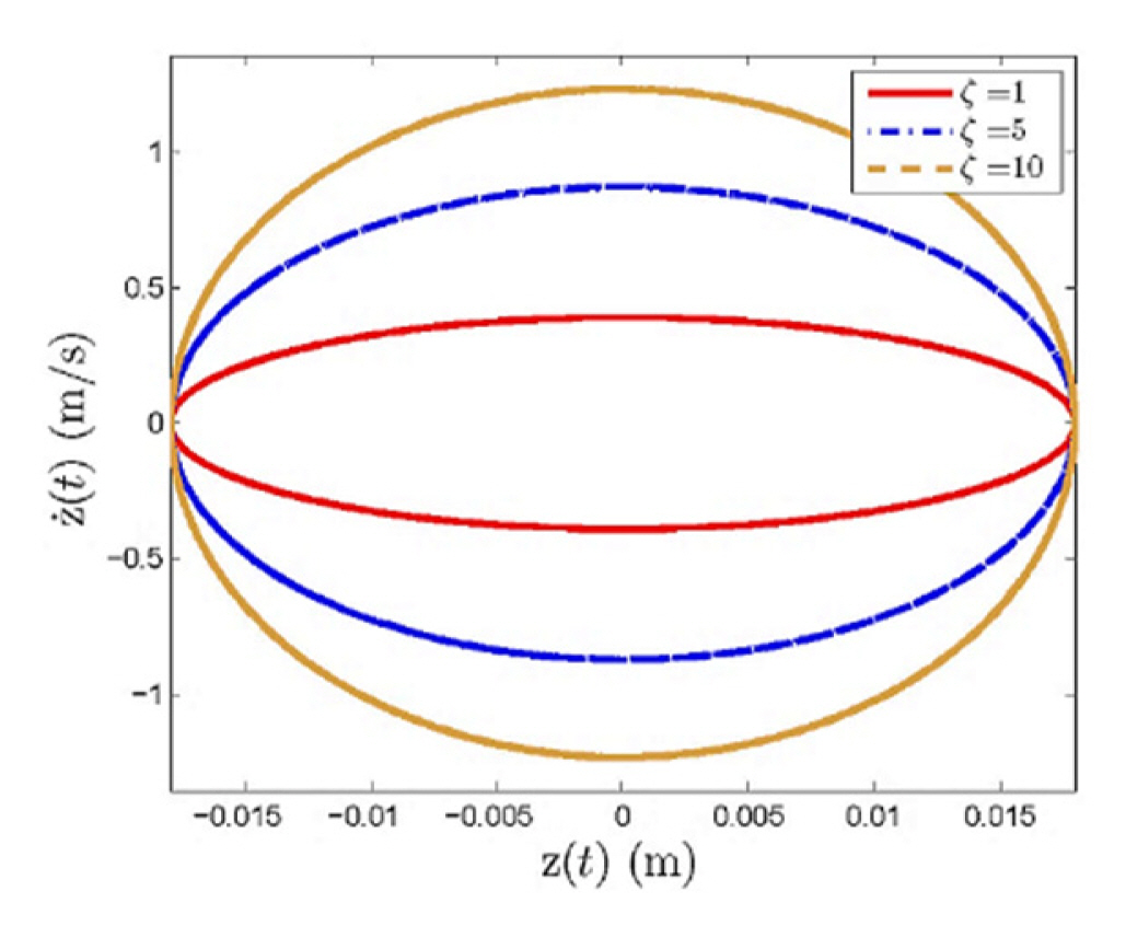
In the first part, we have attempted to verify that a trapped ion in a non-uniform electrostatic field generated by two ionic rings with a common centerline, as illustrated in Fig. 3 is able to exhibit the harmonic motion calculated using Eq. (16). Thus, to conduct numerical studies in this part, all parameters have been set up per the information provided in Table 2, and the numerical results are illustrated in Fig. 4. According to the simulation results shown in Fig. 4(a), we notice that a trapped ion can exhibit oscillatory motion in a non-uniform electrostatic field generated by two ionic rings, as expected, because the motion of a trapped ion is apparently able to demonstrate periodic motion patterns between two rings for every testing parameter condition, where ζ = 1, 5, and 10. To verify the stability of these periodic motions, we establish the phase trajectory plots, as illustrated in Fig. 5, where all setting parameters are provided in Table 2, to ascertain whether the system has stable periodic motions. Based on the phase portrait, we discover that all phase trajectories, ζ = 1, 5, and 10, exhibit an elliptical motion around the equilibrium position at the point of origin without asymptotically stable and unstable evidence, indicating that all trajectories respond in a neutrally stable manner. These simulation results confirm the prospect of confining an ion particle in a non-uniform electrostatic field generated by two ionic rings, based on a one-dimensional speculation.
We also observe that the time interval of oscillation, T, highly depends on the magnitude of the electrical charge, represented by ζ parameter. In Fig. 4(a), it is noticeable that the time interval of oscillation of an ion particle tends to decrease when the ζ parameter value increases, indicating that the system will oscillate at a higher frequency rate if the electrical charge in each ring has greater concentration. We investigate this observation in detail to determine how significantly the electrical charge concentration in an ionic ring influences the time interval of oscillation, per Fig. 4(b), where ζ parameter ranges from 1 to 10. As a result, we observe that the time interval of oscillation, T, is remarkably influenced by ζ parameter, the magnitude of electrical charge in each ring. Specifically, the time interval of oscillation decreases when ζ parameter tends to increase, as expected, which confirms our belief that a trapped ion will respond at a higher frequency at an elevated electrical charge concentration. Lastly, we also find that the time interval of oscillation is considerably dependent on the ring size, represented by ring radius a—that is, an ion particle oscillates at a higher frequency and a shorter time interval when the ring size becomes smaller, as shown in Fig. 4(b).
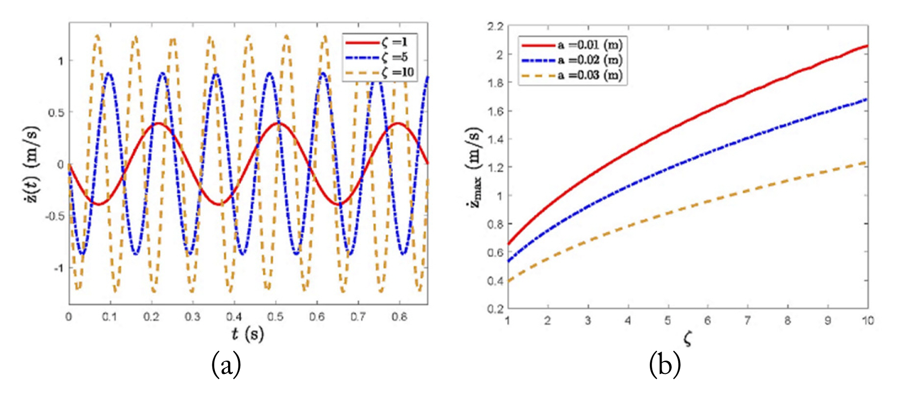
2. Velocity Responses based on Changes in Charge Ratio
In this part, we investigate how the velocity responses of an ion particle in a non-uniform electrostatic field generated by two ionic rings (Fig. 3) differ if ζ parameter, the magnitude of the electrical charge of each ionic ring, has been altered, per the data provided in Table 2. The simulation results discussed in this part are shown in Fig. 6. In Fig. 6(a), we observe that the velocity responses of a trapped ion highly depend on ζ parameter, where ζ = 1, 5, and 10 are used in our study, per the information in Table 2. Regarding the simulation results, it is quite clear that not only does ζ parameter affect the time interval of oscillation of a trapped ion, as discussed earlier, but also has a considerable effect on the amplitude of velocity responses—that is, the amplitude will significantly rise if the magnitude of the electrical charge in each ring becomes higher. To validate the observation in detail, it can be confirmed through another numerical experiment, as shown in Fig. 6(b), where the velocity amplitude of ion oscillation noticeably increases when ζ parameter rises, based on the latter value ranging from 1 to 10. This indicates that an ion particle in a non-uniform electrostatic field is likely to oscillate at a higher velocity when the magnitude of the electrical charge in each ring becomes more concentrated. Another interesting observation is the effect of the ring size, represented by ring radius a, on the velocity amplitude of oscillation, which tends to increase if ring radius a becomes smaller, as illustrated in Fig. 6(b).
VI. Conclusion
In this work, we investigate and analyze the possibility to trap an ion particle in a non-uniform electrostatic field produced by two ionic rings with a common centerline. In our study, a trapped ion is limited to moving in a one-dimensional direction by introducing the hypothetical tube (imaginary tube) to assume that the motion of an ion particle within the tube moves in a one-dimensional direction. To develop the equation of motion of an ion particle, we first derive the electrostatic field generated by two ionic rings by employing the multipole expansion technique under the azimuthally symmetrical charge distribution assumption, where the higher-order expansion terms of Legendre polynomials after order n = 3 are negligible due to the small amplitude oscillation speculation. Then, the equation of motion of an ion particle is developed by means of the Lagrangian formulation. According to the numerical study, the displacement responses of an ionic particle can exhibit a stable periodic motion, verified by displacement responses and phase trajectory plots, which cements the prospect to trap an ion by a proposed electrostatic field within a stability parametric setting, l > 2a. Additionally, we find that the magnitude of the electrical charge of each ring and the ring radius, representing the ring size, significantly influence the frequency and velocity amplitude of the ion oscillation, where an ion particle tends to oscillate at a higher frequency if the charge concentration is greater, but the ring size becomes smaller. We also notice that the velocity amplitude of ion particle oscillation tends to rise when the charge concentration increases, while the ring radius decreases. In future work, we will extend our study to a three-dimensional case to gain more insights and discover the realistic behavior of a trapped ion in a non-uniform electrostatic field, which might lead to the development of the experimental prototyping.