I. Introduction
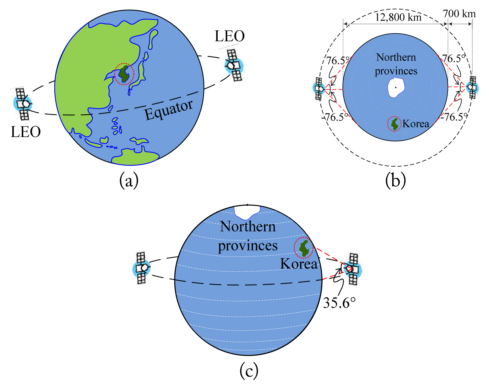
In general, an antenna for communication with a ground station is used in a telemetry, command, and ranging (TC&R) operating system mounted on a low-orbit satellite. As shown in Fig. 1(a), the Korean low-orbit satellite TC&R intends to operate with the concept of two satellites rotating in orbit over the equator. Fig. 1(b) shows that for the radio waves from two satellites to alternately cover the sky over Korea in the low orbit of 700 km, the beamwidth of the satellite-mounted antenna must be ±76.5° or more. In addition, the satellite must stably cover the sky over Korea alternately while orbiting the Earth when the beam of each satellite-mounted antenna maintains a symmetrical beam pattern. As shown in Fig. 1(c), the location of Seoul in Korea is 37.6° north latitude, and the angle from the vertical sky above the equator at 700 km to Seoul is 35.6°. Even if the position of the satellite-mounted antenna changes slightly, a symmetric beamwidth of ±76.5° can cover Korea sufficiently. The cross-polarization level increases as the main beam of a circularly polarized antenna deviates from the central angle when a satellite orbits over the equator. Therefore, low radiation is required to suppress cross-polarization receipt, and back radiation must be minimized to prevent receipt of thermal energy from the sun [1–6].
On the other hand, in the case of a commercialized TC&R antenna, the design frequencies of dual-band right-hand circular polarization (RHCP) are 7.2 GHz and 8.45 GHz, and the beamwidth is 75°. Each bandwidth is 100 MHz, the level of cross-polarization is −15 dBic at ±76.5°, and the size of the antenna is 125 mm × 125 mm × 200 mm [7]. The Korean low-orbit satellite TC&R antenna must have an axial ratio of 3 dB or less in the 0° direction of all frequencies within the bandwidth in the dual bands of 7.1–7.3 GHz and 8.0–8.4 GHz. It should be smaller than the existing antenna for stability during satellite launch. It is also necessary to keep the gain above −5 dBic for co-polarization and below −15 dBic for cross-polarization, on average, at ±76.5° for the link budget [8].
In this study, we propose a dual-band, wide axial ratio bandwidth, circularly polarized antenna with a stepped septum structure in a square waveguide for a Korean low-orbit satellite TC&R. The mode was synthesized by connecting the square and circular waveguides to meet the symmetrical beam pattern and the required co-polarization and cross-polarization levels at ±76.5°. Finally, the corrugate structure was offset in multiple steps on the extended circular waveguide aperture to suppress the back lobe of the cross-polarization We describe these results as follows.
II. Frequency-Modulated Continuous-Wave Radar for Hand Gesture Recognition
Table 1 shows the characteristics required for the Korean low-orbit TC&R antenna. It covers the required frequency bands of 7.1–7.3 GHz and 8.0–8.4 GHz, and the axial ratio at 0° must be less than 3 dB. An axial ratio of 10 dB or less is also required at ±76.5° of the xz-plane and yz-plane [8].
1. Circularly Polarized Rectangular Waveguide
As shown in Fig. 2(a), the height of the basic waveguide was doubled, and circular polarization was formed as polarization rotated within the waveguide along the stepped plane of the septum. In addition, a septum with a stepped structure was inserted into the waveguide [9]. The length of the variables shown in Fig. 2(a) was finely adjusted. From these results, it was found that the variables “a” to “d” in the x-axis direction in the septum determined the axial ratio bandwidth, and the variables “e” to “h” in the z-axis direction determined the axial ratio value. In addition, the variable “e” was able to adjust the axial ratio in the low-frequency band and the variable “h” in the high-frequency band. As a result, we optimized a = 5.5 mm, b = 5.5 mm, c = 9.5 mm, d = 5 mm, e = 15 mm, f = 10.5 mm, g = 4 mm, and h = 12.5 mm. The stepped septum must improve and maintain the circular polarization axial ratio bandwidth in the required band after mode synthesis. It was finally set to three steps by optimizing the length and depth, and the height of each step was finely adjusted. CST Microwave Studio (https://www.3ds.com) was used for the simulation. As shown in Fig. 2(b), the S11 characteristics in the low-frequency band improved, and the bandwidth increased as the diameter of the feeding probe increased from 0.5 mm to 2 mm. This change is attributed to an increase in the surface current path of the feed probe conductor. As shown in Fig. 2(c), the axial ratio was maintained below 3 dB within the required band without a significant change. When the radius of the probe was 2 mm, the average value of the axial ratio was 1.18 dB in the main bands of 7.1–7.3 GHz and 8.0–8.4 GHz. Therefore, the probe diameter has a large influence on input impedance matching, and the stepped septum structure is advantageous for the broadband circularly polarized characteristic. A strong electric field is formed in the part where the distance between the septum section and the inner wall of the waveguide is small because of the electric field formed by feeding vertically, and horizontal polarization is created by the boundary condition. As the electric field moves to the aperture, a difference in the blocking wavelength within the tube occurs because of a gradual difference in spacing between the septum and the inner wall of the waveguide. Therefore, the impedance in the waveguide is changed so that the septum obtains a phase difference of 90° at an appropriate length. As a result, the fed electric field is fed vertically, but a horizontal electric field is generated by the septum. We added data and explanations related to this in Fig. 2(d) and 2(e). That is, the magnitudes of the vertical and horizontal electric fields were equal and orthogonal, and a mutual phase difference of 90° was obtained, resulting in circular polarization. In this study, the RHCP antenna is shown.
2. Mode Synthesis
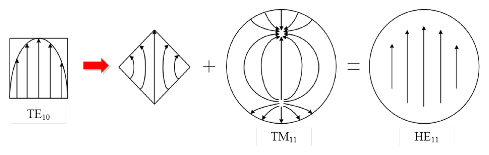
As mentioned in the introduction, we will describe the mode synthesis method adopted to obtain a stable symmetrical radiation pattern. Fig. 3 shows the electric field distribution in the cross-section of the waveguide to explain the mode synthesis principle. The first figure presents the TE10 mode, which is the basic mode of a rectangular waveguide. When circular polarization was generated, not only the perpendicular polarization of the waveguide but also its diagonal polarization was generated by the septum. The electric field formed at an instant relative to the diagonal polarization is shown in the second image of Fig. 3, which is the same as the TE11 mode of the circular waveguide. Next, the horizontally distributed electric field components were cancelled out, leaving only the vertical electric field components when combined with the TM11 mode of the circular waveguide. Therefore, the HE11 mode was formed, as shown in the last figure. Through this, obtaining a wide beamwidth characteristic and a symmetrical beam pattern in the vertical and horizontal planes is possible.
Fig. 4(a) shows a structure in which a square waveguide with a stepped septum is combined with a circular waveguide, and then the latter is extended to 82 mm. Fig. 4(b) and 4(c) presents S11 and the axial ratio at each center frequency of the two bands of 7.2 GHz and 8.2 GHz. S11 was −18.37 dB and −30.82 dB, and the axial ratio was 0.32 dB and 0.99 dB, respectively. Thus, all good characteristics were obtained within the design frequency band. In Fig. 4(d) and 4(e), the antenna radiation patterns at 7.2 GHz were compared to determine the effect of extending the length of the circular waveguide. The co-polarization radiation patterns were confirmed to be symmetric with respect to 0° when the circular waveguide length was 82 mm [10]. In addition, the gain at 0° improved by 4.75 dB, from 4.41 dBic to 9.16 dBic, despite the increase in the co-polarization −5 dBic beamwidth from 145° to 156°. This was due to the electric field being parallelized to the aperture surface by the extended circular waveguide. In the case of the cross-polarization shown in Fig. 4(e), the gain at 0° increased by 8.36 dB from −23.72 dBic to −15.36 dBic, but the back lobe at 180° decreased by 2.67 dB from −4.3 dBic to −6.97 dBic. Similar characteristics were observed at 8.2 GHz.
3. Cross-Polarized Back Lobe Suppression
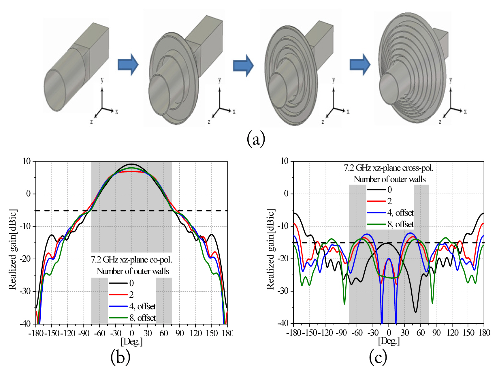
Fig. 5 shows the antenna structure with the outer walls and the simulated results for the purpose of suppressing the cross-polarization level and the back lobe, with the circular waveguide length fixed at 82 mm. A clipping current was formed at the aperture of the circular waveguide into the waveguide sheath, which created the back lobe. To curb this, we installed outer walls, λ/4 or 3λ/4 deep, that served as short-circuit stubs. Because covering with one layer was not possible, a multi-step offset was provided to maximize back lobe suppression. As shown in Fig. 5(a), forward beam focusing characteristics were obtained by setting the outer wall depth to λ/4 and sequentially increasing the number of circular waveguide outer walls [11–13]. As the number of outer walls increased, the back radiation decreased, the main beam gain at 0° increased, and the -3 dB beamwidth became narrower. The outer walls were also modified with an offset structure to widen the width of the main beam and suppress the back lobe of the cross-polarization. Fig. 5(b) and 5(c) shows the co-polarization and cross-polarization radiation patterns according to the number of outer walls and the offset structure. The back lobe gain of the co-polarization was confirmed to be −30 dBic or less; the cross-polarization decreased by 9.89 dB from −5.97 dB to −15.86 dB as the number of outer walls increased. The total number of outer walls was set to 8 and offset. Meanwhile, the gap between the outer wall structures was adjusted by 3 mm, from 1 to 13 mm. The change in S11 and axial ratio was small, but the back lobe level decreased as the spacing between the outer wall structures increased. To meet the target value, it was also optimized to 4 mm, considering the size of the antenna.
III. Antenna Fabrication and Measurement
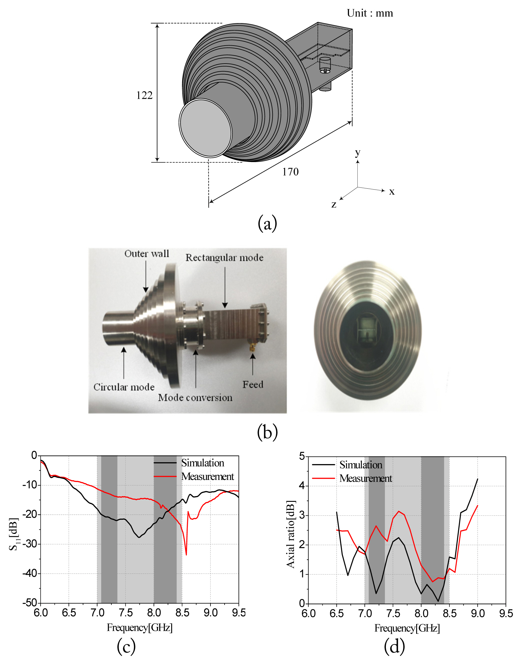
Fig. 6(a) and 6(b) shows the structure of the designed and fabricated antenna. Its length is 170 mm, and its diameter is 122 mm, which is 30 mm shorter than the length of the previously developed antenna of RUAG Holding Ltd. A horn antenna with linear polarization, the FMI-14094-SF40 model of Flann Microwave, Inc. was used as the transmission antenna to measure the axial ratio of the proposed antenna. As a result of the measurement, S11 obtained less than −10 dB in the 7.0–8.5 GHz band, as shown in Fig. 6(c). The axial ratio shown in Fig. 6(d) obtained an average of 2.42 dB and 1.17 dB in the main frequency bands of 7.1–7.3 GHz and 8.0–8.4 GHz, respectively.
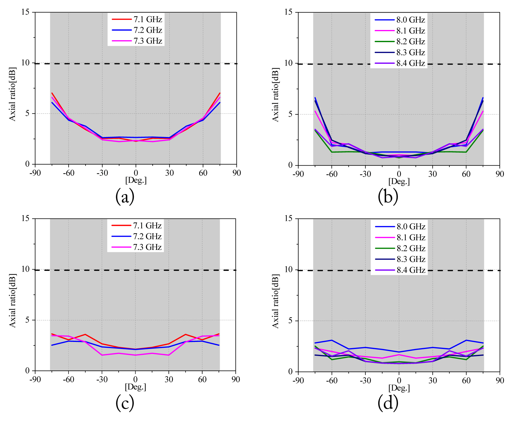
Furthermore, as shown in Fig. 7, the average axial ratio at 0° of each plane obtained 1.8 dB, and the average axial ratio at ±76.5° obtained 4.1 dB. This result meets the requirements indicated in Table 1.
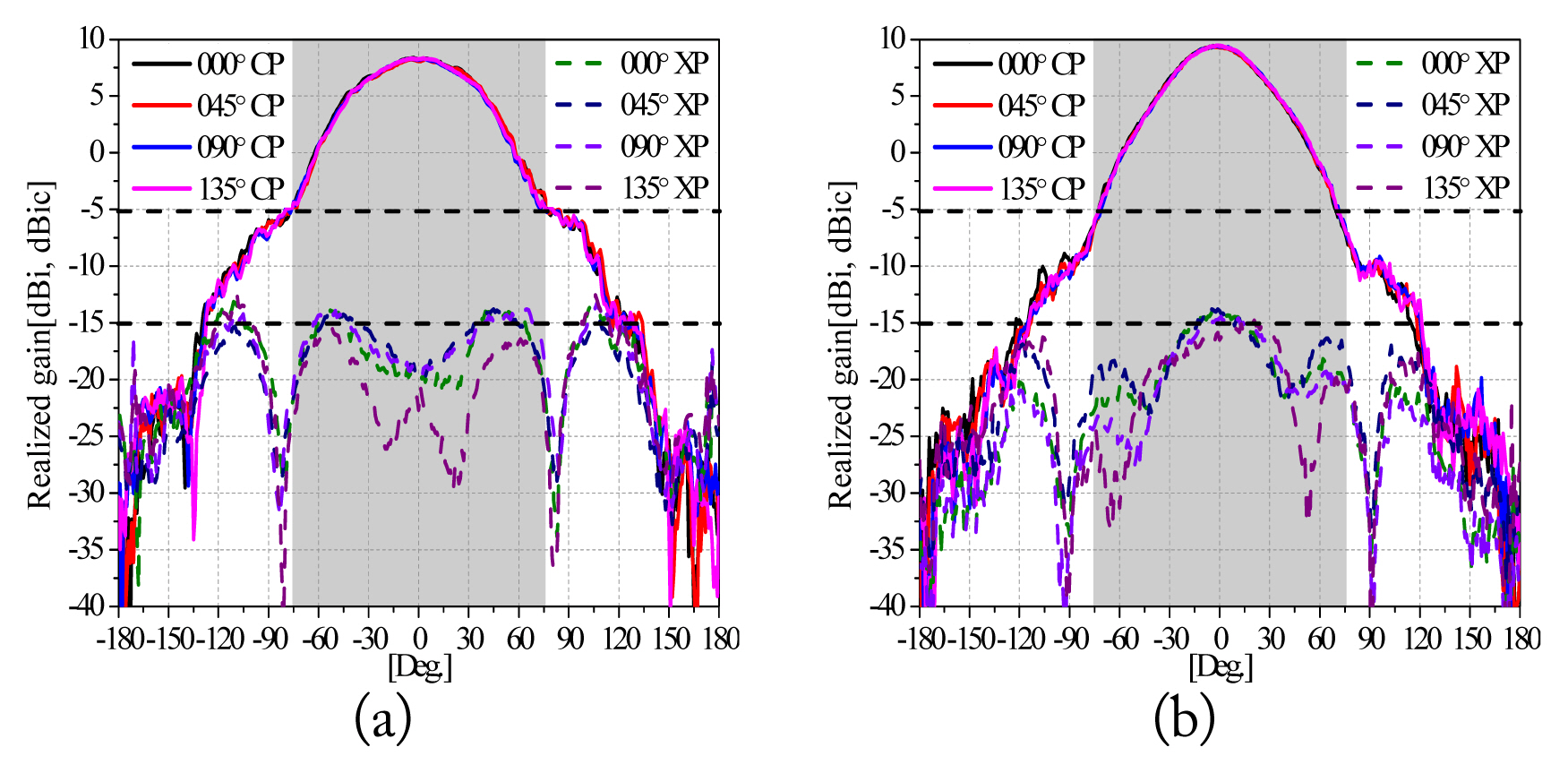
Fig. 8 shows the measured radiation patterns of the proposed antenna. Co-polarization and cross-polarization were measured by fabricating RHCP and left-hand circular polarization (LHCP) microstrip patch antennas at center frequencies of 7.2 GHz and 8.2 GHz for the RHCP antenna proposed in this study. The results in Fig. 8 show that co-polarization was measured using an RHCP microstrip patch antenna, and cross-polarization was measured using an LHCP microstrip patch antenna. This time, the S11 was −27.85 dB, and the axial ratio was 0.96 dB of the RHCP microstrip patch antenna operating at a center frequency of 7.2 GHz. The maximum gain was 8.27 dBic, and the −3 dB beamwidth was 39° at 7.2 GHz. Then, the maximum gain at 8.2 GHz was 9.36 dBic, and a symmetrical pattern of −3 dB beamwidth of 30° was obtained. The average gain at ±76.5° was −4.52 dBic at 7.2 GHz and −5.31 dBic at 8.2 GHz. The 0.31 dB difference from the requirements in Table 1 is considered to be included in the error because of the 1.98 dB axial ratio of the microstrip patch antenna used in the measurement. In the case of cross-polarization, LHCP microstrip patch antennas were fabricated and used for measurement. This time, the S11 was −16.64 dB, and the axial ratio was 2.81 dB of the LHCP microstrip patch antenna operating at a center frequency of 7.2 GHz. As a result, at ±76.5°, the average gain at 7.2 GHz was −19.9 dBic, and at 8.2 GHz, it was −23.6 dBic. The requirement of −15 dBic or less in Table 1 is met.
Table 2 compares and summarizes the important performance targets and measurement results of the proposed antenna.
IV. Conclusion
In this study, an antenna required for TC&R was proposed for satellite–ground station communication. It was a dual-mode waveguide circularly polarized antenna with a bandwidth and symmetric beam of 7.1–7.3 GHz and 8.0–8.4 GHz, which are the main frequency bands within the 7.0–8.5 GHz band. The septum structure was arranged in a stepped shape inside the waveguide to obtain circular polarization characteristics and to increase the axial bandwidth. As a result, the axial ratio of 3 dB or less was met within the required band, and symmetric patterns of −3 dB beamwidths of 39° and 30° were obtained in the 7.2 GHz band and 8.2 GHz band, respectively, using mode synthesis. The cross-polarization back lobe level was also suppressed by 9.89 dB at 7.2 GHz, and an average characteristic of −19.9 dBic or less was obtained at ±76.5° by adding an offset corrugate structure to the outer wall of the waveguide. The proposed antenna was shown to have wide coverage and to secure beam symmetry using a dual mode. It was effective as an antenna for TC&R for satellite–ground station communication, as it met axial ratio and co-polarization and cross-polarization level requirements.