Broadband All-Metal Vivaldi Array Antenna with Pyramidal-Shaped Wings for LEO Satellite Applications
Article information
Abstract
In this paper, we propose an all-metal Vivaldi antenna with pyramidal-shaped conductive wings for use in satellite signal intelligence applications. The inner metal Vivaldi antenna consists of radiating flares and a transition part between the feeder and the flares. The curvature of the inner flares is optimized, while the outer edges of the radiating flares are connected to the pyramidal-shaped wings to obtain a higher antenna gain over the entire operating frequency band. To verify the antenna’s feasibility, performance aspects such as the reflection coefficient, the radiation patterns, and the boresight gain are measured in a full anechoic chamber. The fractional bandwidth of the proposed antenna is 54%, while the boresight gain is greater than 7.3 dBi in the frequency range from 8 GHz to 12 GHz. To examine array performance aspects such as the total gain and beam steering, the proposed Vivaldi antenna is extended to a 4 × 1 linear array configuration. When the main beam is steered from 0° to 15°, the maximum gain is varied from 14.5 dBi to 13.7 dBi, while the side lobe level is decreased from 11.2 dB to 6.3 dB.
I. Introduction
Signal intelligence (SIGINT) applications of low Earth orbit (LEO) or geostationary Earth orbit (GEO) satellites typically require the acquisition of various signals, such as communication signals, radar signals, or instrumentation signals, to perform critical information analyses of wide areas of the Earth [1–5]. Such systems generally rely on broadband array antennas to collect unknown signals over a wide frequency range and to steer the radiation beam to achieve more precise signal detection. To obtain the broadband characteristics required for satellite antennas, previous studies have focused on different types of antennas, including horn antennas, spiral antennas, and log-periodic antennas [6–8]. However, these types of antennas are sometimes difficult to mount on small satellite platforms, which require lightweight and compact antennas. To reduce the antenna weight and size, printed antenna techniques involving various radiator shapes, such as a printed Vivaldi [9–12], an E-shaped patch [13], a U-slot shaped patch [14], and a printed monopole [15, 16], have been reported. Although these antennas can have small geometries and broadband impedance-matching characteristics, it remains challenging to employ the related techniques in satellite systems due to their low durability when taking into account the multifactorial effects of high-temperature and vacuum environments [17–19]. To overcome this durability problem, all-metal antennas, for example, metal Vivaldi antennas [20], slot antennas [21], and biconical antennas [22], have all been investigated. However, these antennas frequently fail to achieve a uniformly high gain over wide operating frequency bands.
In the present paper, we propose an all-metal Vivaldi antenna with pyramidal-shaped wings for use in LEO satellite SIGINT applications. The inner metal Vivaldi antenna consists of radiating flares and a transition part between the feeder and the flares. The lengths of the flares and the transition part are optimized to achieve a uniformly high gain when connected to the pyramidal-shaped wings. In addition, the angle of inclination of the outer flare is adjusted to allow for connection with the wings. The curvature of the inner flares is also adjusted to obtain a uniformly high gain without any pattern distortion in the boresight direction. Moreover, in the transition part, a rectangular cavity is inserted to improve the impedance-matching characteristics [20]. The bottom of the transition part is connected to the ground plate, while the outer edges of the radiating flares are attached to the pyramidal-shaped wings to obtain a higher antenna gain over the entire operating frequency band. To verify the feasibility of the proposed design, the antenna is fabricated, with all the metal components being manufactured by means of the metal mold method to ensure sufficient durability. Antenna performance aspects such as the reflection coefficients, radiation patterns, and boresight gains are then measured in a full anechoic chamber. Furthermore, the beam-steering characteristics of the proposed antenna when in a 4×1 linear array configuration are also investigated. Taken together, the results demonstrate that the proposed array antenna is suitable for use in satellite SIGINT applications.
II. Design of the Proposed Antenna
Fig. 1 illustrates the geometry of the proposed Vivaldi antenna for use in LEO satellite SIGINT applications. The inner metal Vivaldi antenna consists of radiating flares and the transition part between the feeder and the flares. In the depicted configuration, the lengths of the flares (h1) and the transition part (h2) are all optimized to achieve a uniformly high gain when connected to the pyramidal-shaped wings. In addition, the angle of inclination of the outer flare (θi) is also adjusted to allow for connection with the pyramidal-shaped wings. The inner flares of the Vivaldi antenna have an exponential curvature that can be expressed using a function of f(z) as follows [20]:
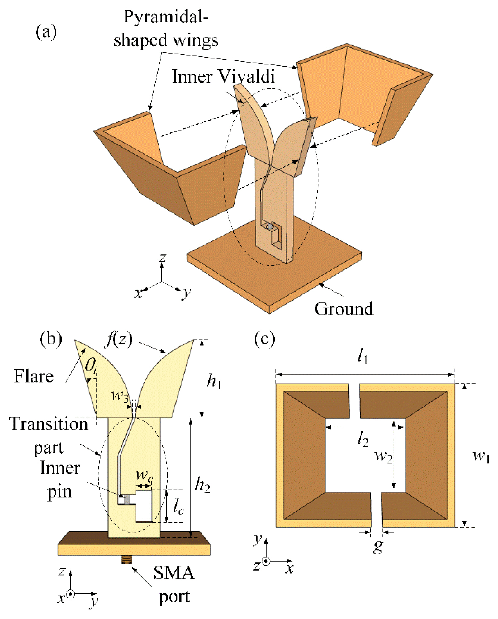
Geometry of the proposed antenna: (a) isometric view, (b) side view, and (c) top view.
The curved flares are designed to obtain a uniformly high gain without any pattern distortion in the boresight direction. The outer edges of the radiating flares are attached to the pyramidal-shaped wings, which also help achieve a higher antenna gain over the entire operating frequency band without the need for a bulky waveguide structure. Here, the width and length of the aperture of the pyramidal-shaped wings are denoted as w1 and l1, respectively. Simultaneously, the width and length of the bottom of the pyramidal-shaped wings are denoted as w2 and l2, respectively. The two wings are located slightly apart from each other, with a gap of g. In the transition part, a rectangular cavity is inserted, which has a width of wc and length of lc, to improve the impedance-matching characteristics. The bottom of the transition part is connected to the ground plate, and all the components of the proposed antenna are manufactured using metal materials to ensure it has sufficient durability. The detailed geometric parameters of the proposed antenna, as listed in Table 1, are derived using a FEKO electromagnetic simulator [23].

Geometric parameters of the proposed antenna
Fig. 2 shows the reflection coefficients and boresight gains according to the type of pyramidal-shaped wings used. Case 1 is a basic Vivaldi antenna without extended wings, while Case 2 is constructed by attaching small conductor wings to the outer edges of the radiating flares. The boresight gains in the two cases exhibit no clear difference, as shown in Fig. 2(b). Yet, when the conductor wings are further extended, as in Case 3, the antenna gain in the boresight direction is significantly improved. In particular, in the low operating frequency band below 9 GHz, the average gain is improved by more than 4 dB. By contrast, when the Vivaldi antenna has a closed aperture shape, which is achieved by further extending the conductor wings, as in Case 4, the gain clearly degrades in the high operating frequency band above 10 GHz. To achieve a uniformly high gain over the entire operating frequency band, the conductor wings should be separated by small gaps. These small gaps create a uniform E-field distribution within the antenna aperture, resulting in a stable and high antenna gain. Case 5 (i.e., the proposed antenna type) shows the optimized boresight gain in the operating frequency band, as demonstrated in Fig. 2(b). The shape of the conductor wings has little effect on the reflection coefficient, as shown in Fig. 2(c). These results indicate that the gain characteristics of the proposed all-metal Vivaldi antenna can be improved while maintaining the impedance-matching characteristics through the use of the pyramidal-shaped wings.
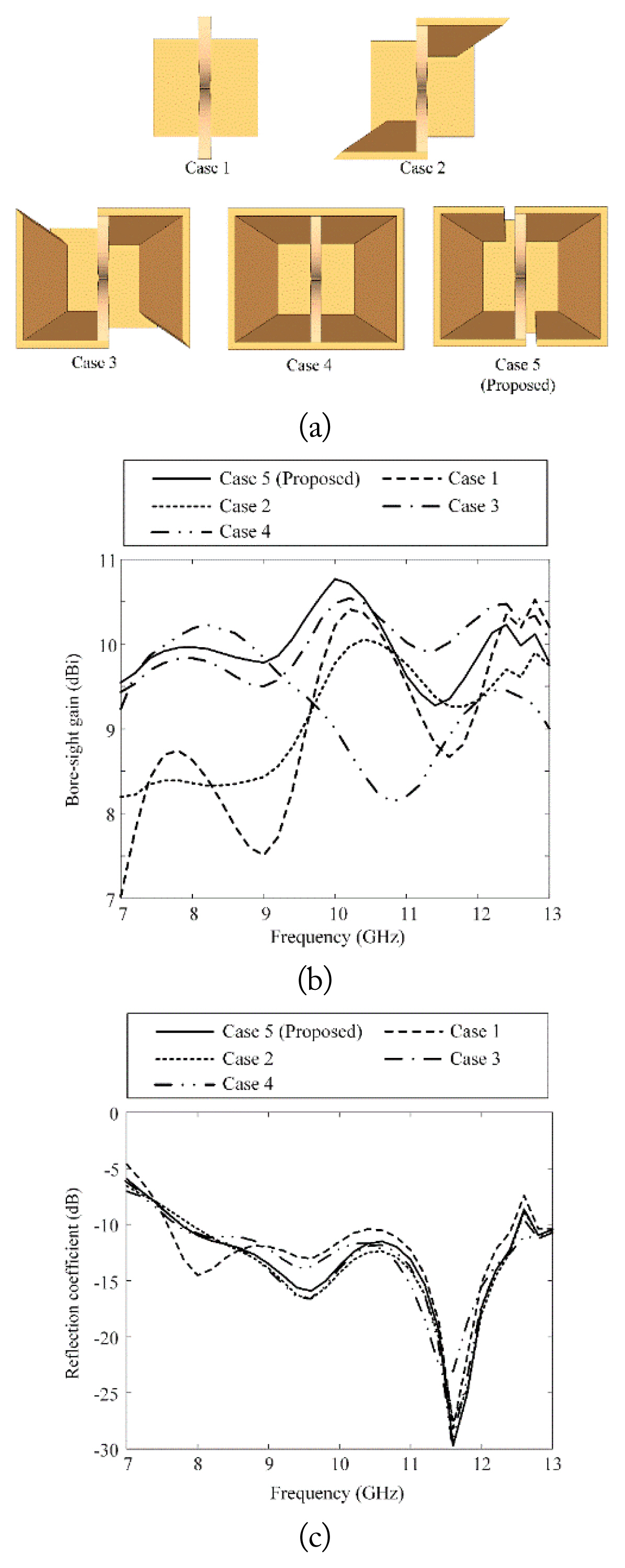
Comparisons according to the extended wing structures: (a) geometries according to the cases, (b) boresight gains, and (c) reflection coefficients.
Fig. 3 presents the bandwidth characteristics of the proposed antenna according to the cavity size. The size of the cavity and the bandwidth of the antenna are proportional to each other. However, if the size of the cavity increases, the thickness of the antenna’s conductor decreases and the durability of the antenna deteriorates. Therefore, we determine the optimal cavity size to be 4.5 mm × 10 mm.
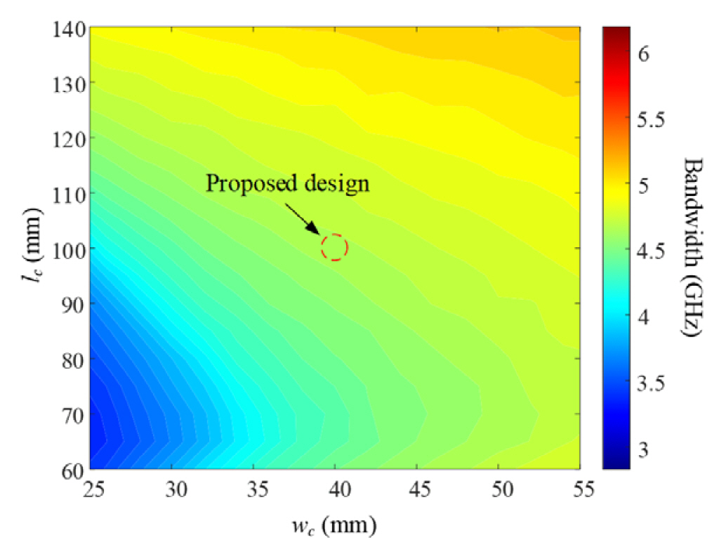
Bandwidth characteristics of the proposed antenna according to the cavity size.
Fig. 4 illustrates photographs of the fabricated antenna. All the metal components of the proposed antenna are manufactured using the metal mold method to ensure it has sufficient durability. The pyramidal-shaped wings are attached to the outer edges of the radiating flares using metal screws, as shown in Fig. 4(a) and 4(b). A subminiature version A (SMA)-type connector is located on the ground plate, while the inner pin of the SMA is connected to the upper conductor of the transmission line via the port hole, as shown in Fig. 4(b) and 4(c). A metal screw is used to fix the SMA connector, as shown in Fig. 4(c). To verify the antenna’s feasibility, its performance in terms of the reflection coefficients, radiation patterns, and boresight gains is measured in a full anechoic chamber, as shown in Fig. 4(d).

Photographs of the fabricated Vivaldi antenna: (a) top view, (b) side view, (c) bottom view, and (d) measurement setup.
Fig. 5 shows the reflection coefficients of the proposed antenna, where the solid and dashed lines indicate the measured and simulated reflection coefficients, respectively. The measured fractional bandwidth is 54% (|Г|dB < −10 dB, 7.3–12.7 GHz), which is in good agreement with the simulation result of 52% (7.8–13 GHz).
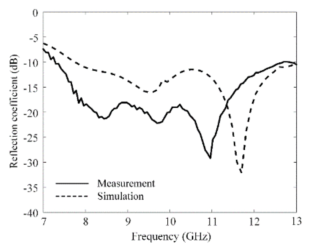
Reflection coefficients of the proposed antenna.
Fig. 6 presents the boresight gains of the proposed antenna. The measured boresight gains are compared with the simulation results. The measured boresight gains are all over 7.3 dBi, with an average of 8.9 dBi, while the average boresight gain determined via simulation is 9.8 dBi. Thus, the boresight gains exhibit uniformly high gain characteristics over the entire operating frequency band. To achieve a uniformly high gain over the entire operating frequency band, the conductor wings should be separated by small gaps, which create a uniform E-field distribution within the antenna aperture, resulting in a stable and high antenna gain. To verify the proposed antenna’s feasibility, its characteristics, such as the bandwidth, average gain, and antenna size, are compared with those from other studies, as listed in Table 2.
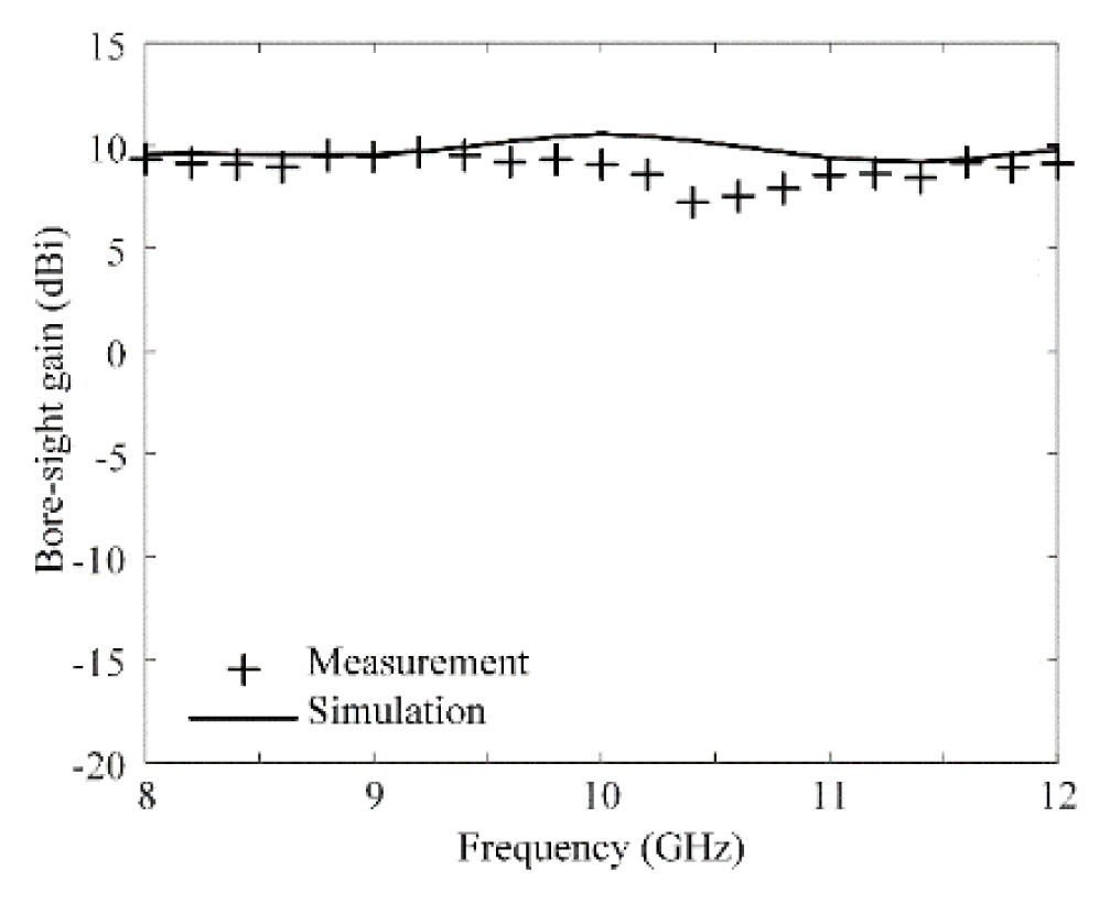
Boresight gains of the proposed antenna.
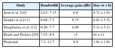
Comparisons of the antenna characteristics
Fig. 7 illustrates the two-dimensional radiation patterns of the proposed antenna in the E-plane (zx-plane) and the H-plane (zy-plane). At 8 GHz, the measured half-power beamwidths (HPBWs) in the E-plane and H-plane are 48° and 55°, respectively, which are in good agreement with the simulated HPBWs of 56° and 52°, respectively, as shown in Fig. 7(a) and 7(b). Moreover, at 10 GHz, the HPBWs in the E-plane and H-plane are 41° and 53°, respectively, according to the measurements, whereas the simulated results under the same conditions are 48° and 36°, respectively, as shown in Fig. 7(c) and 7(d).
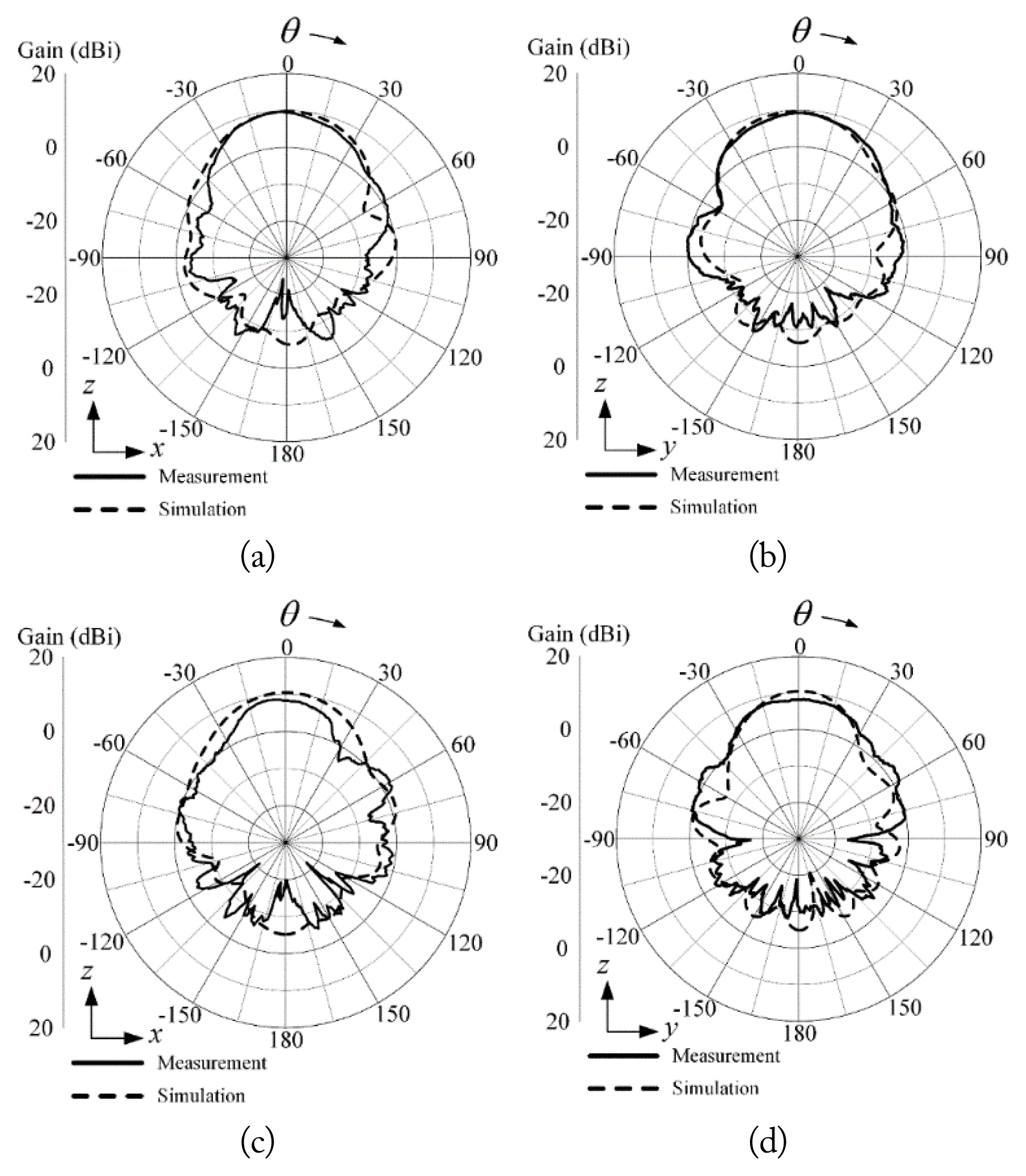
Two-dimensional radiation patterns of the proposed antenna: (a) E-plane at 8 GHz, (b) H-plane at 8 GHz, (c) E-plane at 10 GHz, and (d) H-plane at 10 GHz.
III. Extension to an Array and Measurement
Fig. 8(a) shows an array fabricated using the proposed Vivaldi unit cell structure, including the measurement setup. The proposed Vivaldi array has a 4 × 1 linear array configuration, and the array spacing is 38 mm (1.3λ). In this configuration, the proposed array exhibits an isolation of more than 27 dB between each element. A plastic zig is manufactured using three-dimensional printing technology with an acrylonitrile–butadiene–styrene copolymer (ABS) ink to hold each Vivaldi element, as shown in Fig. 8(a). To examine the antenna’s array gain, the active element patterns (AEPs) of the proposed Vivaldi array at all the ports are measured in a full anechoic chamber. Subsequently, the total array gain is calculated using the AEPs of all the ports based on the following equation [24, 25]:

Photographs of the proposed Vivaldi array: (a) 4 × 1 linear array and (b) measurement setup.
where gi is a complex AEP vector of the ith port and wi is a complex weighting vector of the ith port.
Fig. 9 presents the array gains when steering the beam at 8 GHz. Based on the measurement and simulation, the array gains in the boresight direction are 14.5 dBi and 15.5 dBi, respectively. When the main beam-steering angle is increased from 0° to 15°, the maximum gain decreases from 14.5 dBi to 13.7 dBi, and the side lobe level also decreases from 11.2 dB to 6.3 dB. These results demonstrate that the proposed all-metal Vivaldi antenna can be extended to an array that can be used for LEO satellite SIGINT applications.
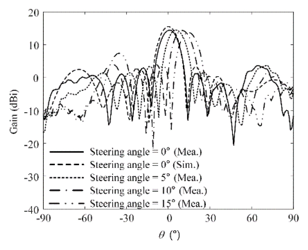
Radiation patterns of the array according to the beam-steering angles at 8 GHz.
IV. Conclusion
We investigated the feasibility of an all-metal Vivaldi antenna with pyramidal-shaped conductive wings for use in satellite SIGINT applications. The inner metal Vivaldi antenna consisted of radiating flares and the transition part between the feeder and the flares. The outer edges of the radiating flares were connected to the pyramidal-shaped wings to obtain a higher antenna gain over the entire operating frequency band without the need for a bulky waveguide structure. The fractional bandwidth of the proposed antenna was 54%, and the boresight gain were greater than 7.3 dBi in the frequency range from 8 GHz to 12 GHz. In addition, at 8 GHz and 10 GHz, the HPBW were 48° and 41° in the E-plane, respectively. The beam-steering characteristics of the proposed antenna with the 4×1 linear array configuration were also investigated. When the main beam was steered from 0° to 15°, the maximum gain varied from 14.5 dBi to 13.7 dBi, and the side lobe level decreased from 11.2 dB to 6.3 dB. Taken together, these results demonstrate that the proposed array antenna is suitable for use in satellite SIGINT applications.
Acknowledgments
This work was supported by a grant in aid from Hanwha Systems.
References
Biography

Doyoung Jang received his B.S. degree in information and telecommunication engineering from Dongyang Mirae University, Seoul, Republic of Korea, in 2018. He worked as a research engineer in MOASOFT, Seoul, Republic of Korea, from 2015 to 2018. He received his M.S. and Ph. D. degrees in electronic and electrical engineering from Hongik University, Seoul, Republic of Korea, in 2020 and 2023, respectively. He is currently working as a research professor at the Metamaterial Electronic Component Research Center at Hongik University, Republic of Korea. His research interests include array antennas, radars, and electromagnetic wave propagation.

Tae Heung Lim received his B.S., M.S., and Ph.D. degrees in electronic and electrical engineering from Hongik University, Seoul, Republic of Korea, in 2016, 2018, and 2022, respectively. He is currently working as a senior researcher at the Agency for Defense Development (ADD), Republic of Korea. His research interests include Global Positioning System antennas, time-modulated arrays, antenna arrays, position optimization of the array elements for adaptive beamforming, and wave propagations for radar applications.

Seulgi Park received his B.S. and M.S. degrees in electrical engineering from Hongik University in 2006 and 2008. respectively. He worked at the Electronic Warfare Research Center of LIG Nex1 corporation from 2008 to 2013, and then from 2013 to 2016, he worked at the DMC Research Center of Samsung Electronics Corporation. Since January 2017, he has worked as a chief engineer in the tactical communication system team of Hanwha Systems. His major research fields include electronic warfare transmission/reception antennas, electronic warfare systems, and tactical communication systems.

Hosung Choo received his B.S. degree in radio science and engineering from Hanyang University in Seoul in 1998, and he recvied his M.S. and Ph.D. degrees in electrical and computer engineering from the University of Texas at Austin in 2000 and 2003, respectively. In September 2003, he joined the School of Electronic and Electrical Engineering, Hongik University, Seoul, Republic of Korea, where he is currently a full professor. His principal areas of research entail the use of the optimization algorithm in developing antennas and microwave absorbers. His studies also include the design of small antennas for wireless communications, reader and tag antennas for radio frequency identification, and on-glass and conformal antennas for vehicles and aircraft.