I. Introduction
Recently, in mobile communication, a wideband antenna has been required because multimedia, such as video, must be transmitted. In contrast, some applications require multiband antennas with a narrow bandwidth. Partial discharge (PD) is a prebreakdown phenomenon in high-voltage equipment. In this case, the PD phenomenon occurs sporadically in several narrow bands over a wide range of bands [
1]. In the terahertz band, even if the bandwidth is 1%, it corresponds to several gigahertz or more. Also, it is not preferred to use power over a wideband because it is more difficult than obtaining the same level of power in a low-frequency band [
2].
Single-feed multiband antennas are also investigated, as summarized in
Table 1. A single-feed antenna can be designed without considering isolation characteristics. However, to obtain multiple resonances, the current path must be diversified, which complicates the resonator. Such a structure has too many design parameters [
3] or is bulky [
4].
In [
5], by changing the number of loaded resonators, the operating frequencies of a slot antenna were easily controlled. In [
6], by loading U-shaped strips outside the radiating aperture of a half-mode substrate-integrated waveguide (HMSIW) cavity, additional resonances can be produced, thus leading to the realization of multiband capability. In [
7], five resonant frequencies were formed by applying a parasitic metal strip to a dielectric resonator (DR). In [
8], a triple-band antenna was designed using an optimization algorithm. Here, one or two additional resonances can be formed.
In this letter, a multi-band antenna was designed. Each time a slot is added, the resonant frequency increases by one, and a decaband antenna is designed. At this time, no other parameters changed. It also shows good matching characteristics, even without a tuning process. To the best of our knowledge, this is the first time a deca-band antenna has been proposed.
II. Deca-Band Antenna
Fig. 1 shows an extension of the quad-band antenna to an
m-band antenna. Here,
m is the number of resonant frequencies of the antenna (
m Ōēź 5). Since the resonant frequency increases in proportion to the number of slots,
m slots are required to implement
m resonance. The slots are added while maintaining the following conditions: first, the distance between slot #1 and the upper side of the patch is 1.1 mm. Second, the distance
dm from the last slot, slot #
m, to the feed point is 19.1 mm. Third, the distance between the two slots was maintained uniformly at 2.8 mm. Accordingly, when each slot is added, the length
L of the patch increases by 2.8 mm, but the other parameters do not change.
Fig. 2 shows the simulated and measured reflection coefficients of antennas with 4, 6, 8, and 10 slots. It was confirmed from the simulation that the resonant frequency of the antenna increases by one as the number of slots is added one by one. The length of each slot varies slightly for the quad-band antenna, but the purpose of the
m-band antenna (
m Ōēź 5) is to verify that the antennaŌĆÖs resonant frequency is generated as slots are added. Therefore, it did not proceed through the optimization process. For this reason, for convenience, the
m-th (
m Ōēź 5) slot is set equal to 28.7 mm ├Ś 0.2 mm.
Fig. 3 shows the simulated and measured gain at
╬Ė = 0┬░. The proposed antenna has a broadside radiation pattern at all 10 resonant frequencies and nine radiation nulls. The measured gain is 1.6ŌĆō3.9 dBi at the resonant frequencies.
III. Design Analysis
Table 2 summarizes the lengths and widths of the slots. As the simulation results show, the impedance-matching characteristics of the antenna are not poor, even without tuning for slot-related parameters.
Fig. 4 shows the resonant frequency from the quad-band antenna to the deca-band antenna according to the distance
df between the feed point and the slot (starting from 14 mm and increasing by 2.8 mm). The following were from the simulation results:
ŌĆó When the location of the slot is close to the feed point (df = 14 mm, 16.8 mm, and 19.6 mm), the resonant frequencies of all antennas do not change significantly. However, when df is greater than 19.6 mm, the resonance frequency is different, even if the distance from the feed point is the same.
ŌĆó When one slot is added to the (mŌĆō1)-band antenna to form an m-band antenna, a new resonant frequency is formed by the added slot. This resonant frequency corresponds to f1 of the m-band antenna. In other words, f1 of the (mŌĆō1)-band antenna becomes f2 in the m-band antenna. At this time, since the distance between the slots is very close at 2.8 mm, f1 and f2 of the m-band antenna are located at a very close distance. Thus, f1 pushes f2 upward.
This phenomenon occurs in a chain, which can be explained as follows. The resonant frequency formed by the slot in which df is located at 30.8 mm is f1 = 3.31 GHz in the hepta-band, f2 = 3.635 GHz in the octa-band, f3 = 3.791 GHz in the nona-band, and f4 = 3.83 GHz in the deca-band. Because f2 of the octa-band is pushed by f1, but f3 of the nona-band is pushed by f1 and f2, and f4 of the deca-band is pushed by f1, f2, and f3, it rises further.
This rise does not occur indefinitely, but it does not increase further when it reaches 4.033 GHz. Although the spacing by the slot is constant, the spacing between the resonant frequencies is the widest between
f1 and
f2. The difference between the two frequencies decreases as the frequency increases. This is because, as mentioned earlier, the resonant frequency is decreased by a new slot added between the slot and the feed point. Because slot forming
f1 exists at the top of the patch, many slots exist between the slot and the feed point in such a way that the length of the current path increases. Accordingly, the lower the frequency, the greater this effect, and the difference between the frequencies increases.
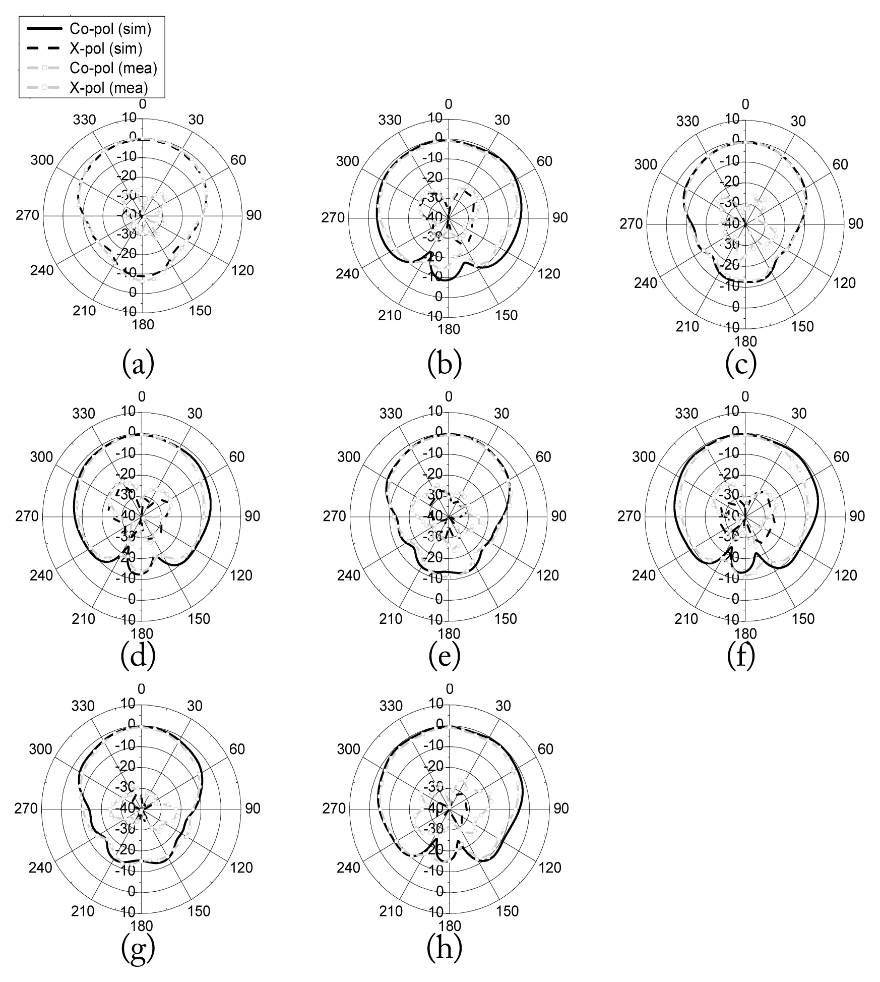
Fig. 5 shows the measured and simulated radiation patterns at the four resonant frequencies.
IV. Conclusion
In this study, a deca-band antenna with a filtering function is implemented by applying six slots to a quad-band antenna. In this case, other parameters do not change except that the length of the patch increases for the additional slot. It also shows good matching characteristics, even without a tuning process.
Acknowledgments
This work was supported by a Kyonggi University Research Grant (2022).
Fig.┬Ā1
Proposed multiband antenna with more than five resonances: (a) top and side view and (b) fabricated antenna.
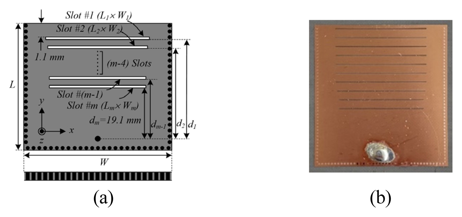
Fig.┬Ā2
Simulated and measured reflection coefficients of the m-band antenna.
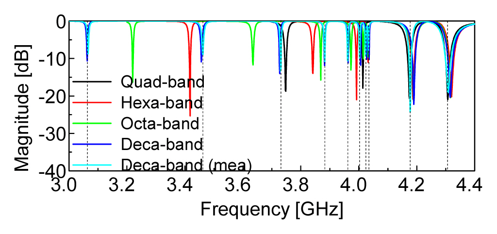
Fig.┬Ā3
Simulated and measured gains of the deca-band antenna.

Fig.┬Ā4
Resonant frequency according to slot position in the m-band antenna.
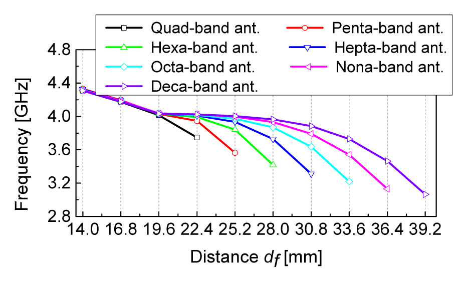
Fig.┬Ā5
Radiation patterns at four resonance frequencies: (a) yz-plane and (b) xz-plane at f2; (c) yz-plane and (d) xz-plane at f4; (e) yz-plane and (f) xz-plane at f6; (g) yz-plane and (h) xz-plane at f8.
Table┬Ā1
Comparison with previous multiband antennas
|
Study |
Freq. (GHz) |
Size |
Gain (dBi) |
Filtering function |
Multi-band extension |
|
Gong et al. [3] |
2.5 / 3.6 / 4.6 / 5.7 |
0.73╬╗0 ├Ś 0.3╬╗0
|
4.9 / 5.9 / 5.5 / 4.9 |
Ō£ś |
Ō£ś |
|
Yang et al. [4] |
1.87 / 2.5 / 3.5 / 6 / 7 |
0.4╬╗0 ├Ś 0.13╬╗0 ├Ś 0.16╬╗0
|
2.5ŌĆō6.8 |
Ō£ś |
Ō£ś |
|
Xie et al. [5] |
2.5 / 3.5 / 5 |
0.96╬╗0 ├Ś 0.69╬╗0 ├Ś 0.01╬╗0
|
4.1 / 3.7 / 4.1 |
Ō£ō |
Ō£ś |
|
Yang et al. [6] |
4.5 / 5 / 5.5 |
0.75╬╗0 ├Ś 0.51╬╗0
|
5.6 / 5.9 / 5 |
Ō£ś |
Δ |
|
Afifi et al. [7] |
2.45 / 3.5 / 4.1 / 4.8 / 5.2 |
NA |
2.6 / 3.7 / 3.3 / 2.7 / 4.6 |
Ō£ś |
Ō£ō |
|
Koziel and Pietrenko-Dabrowska [8] |
2.4 / 3.8 / 5.6 |
NA |
N/A |
Ō£ś |
Δ |
|
This work |
Deca-band |
0.78╬╗0 ├Ś 0.61╬╗0
|
1.6ŌĆō3.9 |
Ō£ō |
Ō£ō |
Table┬Ā2
The length and width of the slots of the m-band antennas
|
Quad-band antenna |
Hexa-band antenna |
Octa-band antenna |
Deca-band antenna |
|
Slot 1 |
28.7 ├Ś 0.2 |
28.7 ├Ś 0.2 |
28.7 ├Ś 0.2 |
28.7 ├Ś 0.2 |
|
Slot 2 |
27.7 ├Ś 0.2 |
28.7 ├Ś 0.2 |
28.7 ├Ś 0.2 |
28.7 ├Ś 0.2 |
|
Slot 3 |
26.7 ├Ś 0.2 |
28.7 ├Ś 0.2 |
28.7 ├Ś 0.2 |
28.7 ├Ś 0.2 |
|
Slot 4 |
26.7 ├Ś 0.2 |
27.7 ├Ś 0.2 |
28.7 ├Ś 0.2 |
28.7 ├Ś 0.2 |
|
Slot 5 |
NA |
26.7 ├Ś 0.2 |
28.7 ├Ś 0.2 |
28.7 ├Ś 0.2 |
|
Slot 6 |
NA |
26.7 ├Ś 0.2 |
27.7 ├Ś 0.2 |
28.7 ├Ś 0.2 |
|
Slot 7 |
NA |
NA |
26.7 ├Ś 0.2 |
28.7 ├Ś 0.2 |
|
Slot 8 |
NA |
NA |
26.7 ├Ś 0.2 |
27.7 ├Ś 0.2 |
|
Slot 9 |
NA |
NA |
NA |
26.7 ├Ś 0.2 |
|
Slot 10 |
NA |
NA |
NA |
26.7 ├Ś 0.2 |
References
1. T. Bandi and S. Ohtsuka, "A multiple narrow band antenna for detection of discharge-emitted electromagnetic waves for insulation diagnostic,"
IEEJ Transactions on Electrical and Electronic Engineering, vol. 15, no. 12, pp. 1751ŌĆō1757, 2020.
https://doi.org/10.1002/tee.23249

2. Y. Liu, S. G. Park, and A. M. Weiner, "Enhancement of narrow-band terahertz radiation from photoconducting antennas by optical pulse shaping,"
Optics Letters, vol. 21, no. 21, pp. 1762ŌĆō1764, 1996.
https://doi.org/10.1364/OL.21.001762

3. Y. Gong, S. Yang, B. Li, Y. Chen, F. Tong, and C. Yu, "Multi-band and high gain antenna using AMC ground characterized with four zero-phases of reflection coefficient,"
IEEE Access, vol. 8, pp. 171457ŌĆō171468, 2020.
https://doi.org/10.1109/ACCESS.2020.3024982
4. G. Yang, S. Zhang, J. Li, Y. Zhang, and G. F. Pedersen, "A multi-band magneto-electric dipole antenna with wide beam-width,"
IEEE Access, vol. 8, pp. 68820ŌĆō68827, 2020.
https://doi.org/10.1109/ACCESS.2020.2986292
6. X. Yang, L. Ge, Y. Ji, X. Zeng, and K. M. Luk, "Design of low-profile multi-band half-mode substrate-integrated waveguide antennas,"
IEEE Transactions on Antennas and Propagation, vol. 67, no. 10, pp. 6639ŌĆō6644, 2019.
https://doi.org/10.1109/TAP.2019.2924991
7. A. I. Afifi, A. B. Abdel-Rahman, A. S. Abd El-Hameed, A. Allam, and S. M. Ahmed, "Small frequency ratio multi-band dielectric resonator antenna utilizing vertical metallic strip pairs feeding structure,"
IEEE Access, vol. 8, pp. 112840ŌĆō112845, 2020.
https://doi.org/10.1109/ACCESS.2020.3002789
8. S. Koziel and A. Pietrenko-Dabrowska, "Expedited feature-based quasi-global optimization of multi-band antenna input characteristics with Jacobian variability tracking,"
IEEE Access, vol. 8, pp. 83907ŌĆō83915, 2020.
https://doi.org/10.1109/ACCESS.2020.2992134


