I. Introduction
In airborne radar, clutter signals with Doppler frequencies that correspond to the radar platform speed are received. Such clutter signals can degrade the detection range performance of the radar by reducing the signal-to-clutter-and-noise ratio. Thus, a high pulse repetition frequency (HPRF) waveform is often used to improve the detection range of the radar due to its clutter-free characteristic in the target velocity (or the Doppler frequency) range of interest [1].
However, since HPRF is ambiguous in range, it is required to resolve the range ambiguity for measuring the targetŌĆÖs slant range. One method for resolving the range ambiguity in HPRF is frequency modulation (FM) ranging [2ŌĆō5]. In FM ranging, the carrier frequency of each transmit pulse is linearly increased (or decreased) based on its chirp rateŌĆöalso called frequency modulated interrupted continuous wave (FMICW)ŌĆöand the range is measured from the difference between the carrier frequency of the transmitted pulse and that of the received pulse.
Unlike pulses with a fixed carrier frequency, the Doppler frequency of a target echo or a clutter signal changes linearly with the range due to changes of the carrier frequency in FM ranging. More specifically, the clutter signal spreads in Doppler frequency domain depending on the chirp rate of FM. Thus, conventional clutter rejection in the Doppler frequency band of a pulse Doppler radar is not suitable for FM ranging radar (as described in Section II).
In [4ŌĆō7], HPRF waveform with FM ranging has been designed considering the spread of clutter Doppler frequency, but no guideline for an optimum clutter rejection frequency design is provided. In this paper, clutter rejection method for FM ranging airborne radar considering the Doppler frequency spread to improve the detection performance of airborne radar. Specifically, the optimum clutter rejection frequency is derived in a closed form by calculating the maximum Doppler frequency of the spread clutter signal caused by FM ranging.
This paper is organized as follows: in Section II, the Doppler frequency spread phenomenon in FM ranging is reviewed. Then, in Section III, the optimum clutter rejection frequency for a given radar environment is derived, and the detection performance improvement is analyzed through simulation examples. In Section IV, the flight test result is provided, and the paper is summarized in Section V.
II. Doppler Frequency Spread in FM Ranging
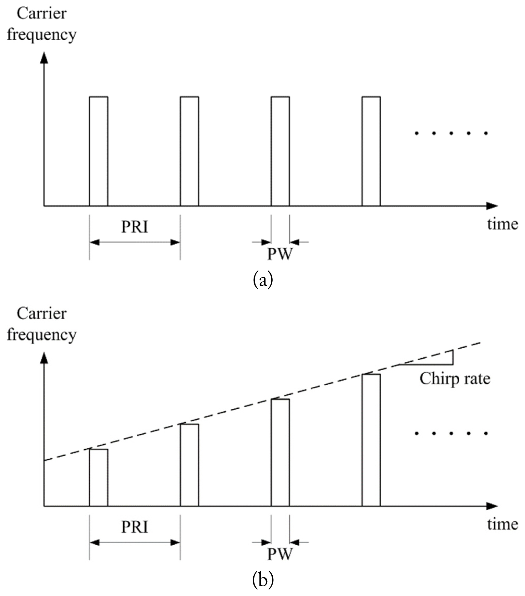
For conventional pulse Doppler radar, the carrier frequency of each transmit pulse is constant, as shown in Fig. 1(a). On the other hand, the carrier frequency changes linearly in FM ranging, as shown in Fig. 1(b). The chirp rate (the rate of carrier frequency change) k can be positive or negative depending on the radar system design. Usually, a positive value of k is preferred since the spread of the clutter Doppler frequency does not intrude into the Doppler frequency band of interest [5]. The following example provides a simple illustration for how Doppler frequencies of clutter and target signal change depending on k. Fig. 2 shows a situation where the radar platform is moving with velocity vr and the radar is illuminating its main beam (or mainlobe) toward a target moving with velocity vtgt at range rtgt. The main beam steering angle with respect to the platform velocity vector is Žłs. If the projection angle of the target velocity vector toward the radar is ╬Ė, then the Doppler frequency of the target echo ftgt is given as
where ╬╗ is the wavelength of the radar waveform.
To satisfy clutter-free condition for detecting the target, it is required to perform signal processing for only the signal with frequency that is higher than the maximum Doppler frequency of clutter, fslc,max (i.e., reject the signal with a frequency lower than fslc,max). Without FM ranging (k = 0), fslc,max is given as follows after compensating the radar platform velocity.
Therefore, the optimum clutter rejection frequency frej = fslc,max, and the clutter-free condition is satisfied as long as ftgt > fslc,max regardless of the target range. Suppose that the range of the target varies from r2 to r1 with the constant Doppler frequency (fi = ftgt where i = 1, 2) as shown in Fig. 3(a) where both mainlobe clutter (MLC) and sidelobe clutter (SLC) are presented with the target. The target echo is kept in the clutter-free region independent of the range change. However, when k > 0, the Doppler frequencies of both the clutter and target signals are linearly reduced with range. Thus, fi is no more independent of ri, but is given as
where c0 is the speed of light. As shown in Fig. 3(b), when the target is at r2, the target cannot be detected if frej is kept as fslc,max since f2 > fslc,max. After the target approaches close enough so that its Doppler frequency is higher than fslc,max, the clutter-free condition is satisfied. For instance, the target can be detected when it is at r1 since f1 > fslc,max. To detect the target at r2 when k > 0, it is required to find the new rejection frequency to avoid clutter.
III. Optimum Clutter Rejection Frequency for FM Ranging Airborne Radar
To satisfy clutter-free condition when k > 0, the optimum rejection frequency can be found as follows. The Doppler frequency of clutter fc at angle Žłc with respect to the platform velocity vector and range rc when k > 0 is given as (without compensating the radar platform velocity).
When the radar platform height is hr, rc can be expressed as
where ╬Ėd is a depression angle (with respect to the platform velocity vector) toward clutter. The maximum Doppler frequency in the same clutter range is given when azimuth angle is zero, i.e., Žłc = ╬Ėd. Thus, by letting ╬Ėd = Žłc and substituting sinŽłc to Žü, from (4) and (5), fc is given as a function of Žü as follows:
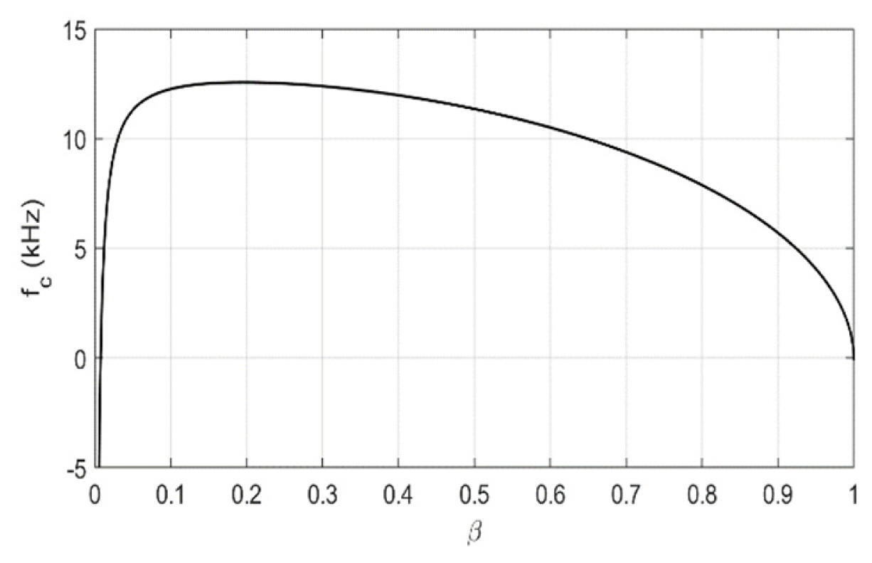
Fig. 4 shows fc as a function of Žü when k = 5 MHz, hr = 10,000 ft, velocity vr = 200 m/s, and ╬╗ = 0.03 m. The value of Žü at maximum fc can be found as a root of the derivative of fc(Žü) as follows.
where
╬▒ = ( k ╬╗ h r c 0 v r ) 2
Finally, Žłc for the maximum Doppler frequency of clutter, Žłc,max is given as
and from (6) and (10), the optimum clutter rejection frequency for k > 0 is given as follows after compensating the radar platform velocity.
The following simulation examples show how frej calculated from (11) can improve the detection performance when k > 0.
Assuming that the radar platform altitude hr = 10,000 ft, velocity vr = 200 m/s, and the radar beam steering angles in azimuth and elevation (╬Ėaz, ╬Ėel) = (30┬░, ŌłÆ15┬░), the clutter signals in range-velocity domain with backscattering coefficient shown in Fig. 5 have been generated as in Fig. 6, for k = 0, 5 MHz/s, and 10 MHz/s, respectively. The clutter signal has been calculated for 50 m ├Ś 50 m range cell, and the detailed process for the clutter signal generation is in [8] and is not provided in this paper for brevity. Note that noise has not been considered for the simulation. Also, to provide more intuitive information, the signals have been provided not in range-Doppler domain but in range-velocity domain.
In Fig. 6, the red dashed lines indicate the velocity corresponding to fslc,max from (2 ). As described in the previous section, it is shown in Fig. 6(a) that frej = fslc,max when k = 0. In this case, frej = 2.181 kHz which corresponds to the rejection velocity vrej = 32.69 m/s when the carrier frequency is 10 GHz. Thus, the echo signal from any target with a velocity higher than vrej can satisfy the clutter-free condition regardless of its range.
However, as k increases, the range of the target that satisfies the clutter-free condition is reduced. In Fig. 6(b) and 6(c), the green-dotted lines indicate the range of the target echo signal with velocity vt = 60 m/s. If the rejection frequency is kept as fslc,max for k = 5 MHz/s, then the maximum range at which the echo signal can be processed is rt,max = 54.61 km, which is indicated as the point (a) in Fig. 6(b). In other words, if the target is located farther than rt,max, it cannot be detected. By setting frej as the frequency that can be calculated by (11), rt,max can be increased. In Fig. 6(b), frej is calculated as 1.098 kHz which corresponds to vrej = 16.46 m/s (vrej is indicated as the yellow-dashed line) and as a result, rt,max is increased to 87.08 km, which is indicated as the point (b) in Fig. 6(b).
A similar situation is observed for the case when k = 10 MHz, as shown in Fig. 6(c). For the same target with velocity vt = 60 m/s, rt,max = 32.69 km (point (a)), when frej = fslc,max, but rt,max is increased to 53.16 km (point (b)) when frej = 0.456 kHz which corresponds to vrej = 6.84 m/s.
IV. Flight Test Results
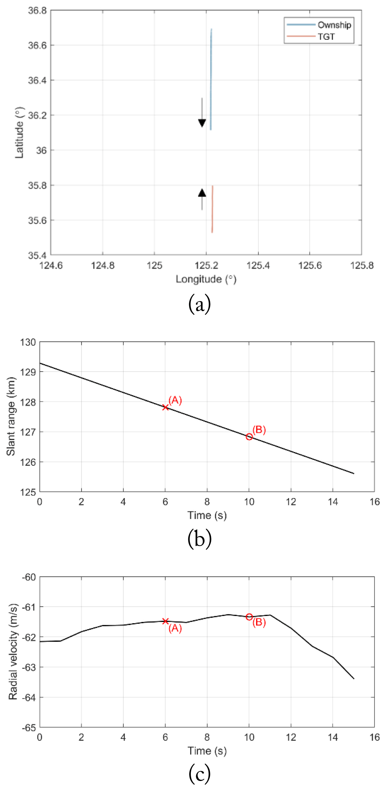
In this section, the flight test results to verify the proposed clutter rejection frequency are provided. The test scenario is shown in Fig. 7(a). An ownship (radar platform) flies from north to south (heading 180┬░) at altitude aown = 12 kft with ground velocity vown = 184 m/s, while a target, starting from approximately 130 km away from the ownship, flies from south to north (heading 0┬░) at altitude atgt = 12.4 kft with ground velocity vtgt approximately ŌłÆ61.5 m/s.
The slant range of the target from the radar and its radial velocity are shown in Fig. 7(b) and 7(c), respectively. During the test, the radar attempts to detect the target with HPRF waveform using FM ranging. In this paper, the detailed waveform parameters such as pulse repetition frequency (PRF), carrier frequency, and chirp rate are not disclosed for security reasons.
At first, the radar attempted to detect the target (i.e., direct the beam toward the target) when the target slant range rtgt = 127.8 km and vtgt = ŌłÆ61.5 m/s, as marked with red ŌĆ£xŌĆØ symbols in Fig. 7(b) and 7(c) (point (A)). Then, the radar attempted to detect the target again when the target slant range rtgt = 126.8 km and vtgt = ŌłÆ61.3 m/s, as marked with red ŌĆ£oŌĆØ symbols in Fig. 7(b) and 7(c) (point (B)). For each point, the received echo signals in range-Doppler domain after matched filtering and Doppler processing are shown in Figs. 8 and 9. The frequencies correspond to fslc,max and frej are shown with dashed red and yellow lines, respectively. It is observed that, while the red lines are displaced from the maximum Doppler frequency of the clutter signals, the yellow lines are located at the maximum Doppler frequency of the clutter signals, proving that frej is the optimum clutter rejection frequency.
At the point (A), the clutter rejection frequencies calculated from Eqs. (2) and (11) are fslc,max = 8.547 Hz and frej = ŌłÆ929.851 Hz, respectively. The received echo signal in range-Doppler domain after matched filtering and Doppler processing is shown in Fig. 8(a) and 8(b). Fig. 8(a) shows the entire range-Doppler domain (with range from 0 to unambiguous range, and Doppler frequency from ŌłÆ0.5PRF to 0.5PRF), while Fig. 8(b) is a close-up of Fig. 8(a) for Doppler frequency around the clutter rejection frequencies. Since the target echo is within clutter region, it is not visible and cannot be detected even if the radar rejects the signals with Doppler frequencies lower than frej.
At the point (B), the target has the similar velocity but is closer to the radar compared to the point (A). The clutter rejection frequencies calculated from Eqs. (2) and (11) are fslc,max = 7.333 Hz and frej = ŌłÆ930.111 Hz, respectively. The received echo signal in range-Doppler domain after matched filtering and Doppler processing is shown in Fig. 9(a) and 9(b). Unlike the case of the point (A), the target echo is now visible since it is in clutter-free region. If the clutter rejection frequency is set as fslc,max (shown with the red dashed line), the target cannot be detected even when it is in the clutter-free region. On the other hand, by setting the clutter rejection frequency as frej, the target can be detected while rejecting the undesired clutter signals sufficiently.
V. Conclusion
In this paper, the optimum clutter rejection frequency selection for FM ranging airborne radar considering the Doppler frequency spread to improve the detection performance of the radar has been proposed. The optimum clutter rejection frequency is derived with a closed form by calculating the maximum Doppler frequency of the spread clutter signal due to FM ranging. By simulation and flight test, it has been verified that the proposed clutter rejection frequency matches with the maximum Doppler frequency of the clutter signals, and that the target which cannot be detected when the clutter rejection frequency is set as fslc,max can be detected by replacing the frequency as frej.