Attenuation Effects of Plasma on Ka-Band Wave Propagation in Various Gas and Pressure Environments
Article information
Abstract
This work demonstrates attenuation effects of plasma on waves propagating in the 26.5–40 GHz range. The effect is investigated via experiments measuring the transmission between two Ka-band horn antennas set 30 cm apart. A dielectric-barrier-discharge (DBD) plasma generator with a size of 200 mm × 100 mm × 70 mm and consisting of 20 layers of electrodes is placed between the two antennas. The DBD generator is placed in a 400 mm × 300 mm × 400 mm acrylic chamber so that the experiments can be performed for plasma generated under various conditions of gas and pressure, for instance, in air, Ar, and He environments at 0.001, 0.05, and 1 atm of pressure. Attenuation is calculated by the difference in the transmission level, with and without plasma, which is generated with a bias voltage of 20 kV in the 0.1–1.4 kHz range. Results show that the attenuation varies from 0.05 dB/m to 9.0 dB/m depending on the environment. Noble gas environments show higher levels of attenuation than air, and He is lossier than Ar. In all gas environments, attenuation increases as pressure increases. Finally, electromagnetic models of plasmas generated in various conditions are provided.
I. Introduction
Plasma is a state of matter consisting of ionized gas. A typical example of the application of plasma is utilizing its response to electromagnetic fields to etch dielectrics in the process of fabricating semiconductors. It is well known that the propagation of electromagnetic waves is attenuated when plasma is introduced in their path. The attenuation characteristics of plasma are affected by the collision frequency and the electron density, which has been deeply investigated both theoretically [1–5] and experimentally [6–13].
Research on the attenuation effects of plasma on electromagnetic waves resulted in an important application of plasma: reducing the radar cross section (RCS) of a target to improve its low observability to radars [11–13]. In [11], measurement of a 12 cm × 12 cm metallic plate plasma showed no significant effect on the RCS, which the authors speculate is due to the very limited life time of the free electrons and the small extent of the plasma sheath. However in [12], RCS reduction of as much as 3 dB was demonstrated experimentally at 7.4 GHz for a 20 cm × 20 cm rectangular metallic plate with a circular dielectric-barrier-discharge (DBD) plasma generator. Finally, [13] reports that the frequency of maximum RCS reduction for a 20 cm × 20 cm rectangular metallic plate can be tuned by varying the number of electrodes that generate plasma, that is, by the area and location of the generated plasma.
In this work, the attenuation effects of plasma on propagating Ka-band waves is investigated experimentally. A DBD generator consisting of 20 layers of electrodes is fabricated. Then the generator is centered between two Ka-band antennas that are set 30 cm apart. The DBD generator is placed in an acrylic chamber to investigate the difference in the attenuation effects of plasmas generated under various gas and pressure environments. Then the transmission is measured in the Ka-band with and without plasma; the difference is the electromagnetic attenuation caused by the generated plasma. Experimental results are presented along with an electromagnetic model of the plasma obtained based on the experimental results.
II. Experimental Setup
The reduction of monostatic RCS of metallic plates due to plasma as described in [12, 13] is largely due to its reflection characteristics. However, the purpose of this work is to investigate the effect of plasma on the transmission of electromagnetic waves in the Ka-band. Therefore, the plasma must be more than a large fraction of the wavelength in the direction of propagation of the plasma.
Fig. 1 shows the proposed parallel electrode DBD generator for investigation of the attenuation effects of plasma on electromagnetic waves in the Ka-band. The electrodes of the DBD generators are placed laterally in [12, 13] to generate a planar plasma, thus transforming the shape of the DBD generator electromagnetically. In contrast, we stack the electrodes vertically, as shown in in Fig. 1. When plasma is generated between the two electrodes by applying a bias, the propagating wave must pass through the plasma layer, whose extent is between the depth of the electrode and the substrate, 60 mm and 100 mm, respectively. This corresponds to 5.2–8.7 free space wavelengths at 26 GHz, the lowest frequency in the Ka-band. This is sufficient to observe the absorbing effect of plasma.
Parallel electrode DBD structure. (a) (b)
There are a total of 20 electrodes, each 120 mm wide, with a gap of 2.4 mm between each electrode, which is maintained using 2.4-mm-thick dielectric pieces. Thus, the total size of the electrode is 200 mm × 100 mm × 70 mm. Although it is not shown in Fig. 1, acrylic poles are used for vertical alignment of the electrodes. Alumina substrates are used to minimize structural deformation such as bending in order to prevent plasma arcs even at low bias levels.
The DBD structure is placed in a 400 mm × 300 mm × 400 mm acrylic chamber (48 L in volume). The chamber is hermetic with 3-cm-thick walls such that the pressure inside the chamber can be reduced to 1 Torr, or approximately 0.001 atm.
A diagram of the complete setup is shown in Fig. 2(a). The chamber is placed between two MTG SGH-40 Ka-band standard horn antennas. The longer the distance between the two antennas, the more vulnerable the measurement is to any misalignment between the antennas. The shorter the distance, the more difficult it becomes to remove multipath signals by gating the time-domain response. In this work, the two antennas are separated by 30 cm, which is an optimal distance.
Experimental setup. (a) Complete experimental setup and (b) Photograph of experimental setup.
Bias voltage is applied using a Keysight 33500B waveform function generator and amplified via a Trek Model 10/40A high-voltage power amplifier. The transmission is measured in the Ka-band using an Anritsu 37247D Vector Network Analyzer. The time-gating function and an in-house algorithm are utilized to find the exact location and width of the time window, which is critical in obtaining accurate responses. Fig. 2(b) shows a photograph of the setup.
III. Plasma Generation in Various Environment
The purpose of this work is to investigate the attenuating effects of plasma on Ka-band electromagnetic wave propagation. Another important purpose is exploring the difference in the effect for plasmas generated under different conditions. In this work, transmission is measured with and without plasma generated in three different gas environments: air, Ar, and He. For each gas, the effect is measured at three different pressure levels: 1, 0.05, and 0.001 atm.
First, the pressure inside the chamber is reduced to 0.001 atm. Then gas is introduced to the chamber until the chamber is completely filled or when the pressure recovers to 1 atm. This is repeated three times to ensure that the chamber is filled with the gas being tested. After the first measurement at 1 atm, the pressure is lowered to 0.05 atm. After the second measurement at 0.05 atm, pressure is further reduced to 0.001 atm and a final measurement is taken.
For each set of conditions, the transmission between the antennas is measured with and without the plasma.
Accurate investigation requires maintaining a stable discharge. This is possible when the applied bias voltage is sufficiently higher than the breakdown voltage, the minimum voltage at which the plasma is generated.
Table 1 summarizes the breakdown voltages for the parallel electrode DBD generator in Fig. 1 for every gas and pressure condition tested in this work. At 1 atm, the minimum bias voltage required to generate plasma is highest in air and lowest in the He environment. This is because noble gases such as Ar and He are much less reactive than air. At lower pressures, the minimum bias voltage decreases dramatically, which reaches saturation at some point.
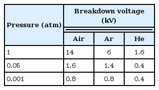
Measured breakdown voltage (frequency: 1 kHz)
For instance, at 1 atm, the minimum voltage for air is more than twice than that for Ar. However, at 0.05 atm, the difference is within 15% and vanishes at 0.001 atm. Saturation in the bias voltage occurs at a higher pressure for He, so the minimum bias levels at 0.05 atm and 0.001 atm are the same. When the pressure decreases, the bias voltages decreases, because there are fewer collisions between electrons and gas in the lower pressure. In other words, when the pressure is low, the distance between the electrons and gas molecules is high. To generate same amount of plasma at different pressures, low bias voltage is required at low pressures.
Fig. 3 shows photographs of the plasmas generated at 0.05 atm for all three gases. As can be seen, the three plasmas have different colors; the air plasma is dark blue, the Ar plasma is purple, and the He plasma is orange.

Plasmas generated at various gas environments at 0.05 atm. (a) Air, (b) argon, and (c) helium plasma.
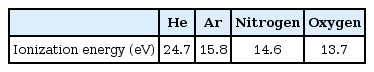
These different colors are due to the different energy levels of the plasma ions. The ionization energies of various gas ions are summarized in Table 2. Helium ions have the highest ionization energy level, while Ar, nitrogen, and oxygen ions have similar energy levels. Because air is mostly nitrogen and oxygen, the air and Ar plasmas are similar in color while He contains more red due to its substantially higher ionization energy.
IV. Experimental Results
Using the experimental setup shown in Fig. 2, the transmission is measured in the entire Ka-band between the two antennas with and without plasma generated under various gas and pressure conditions. The difference between the two transmissions corresponds to the attenuation due to the plasma.
Fig. 4 shows the measured attenuation. For all gas conditions, the attenuation effects of plasma become larger at higher pressure levels. This is due to the increased number of ions present at higher pressures.

Measured (thick lines) and simulated (thin lines) results of attenuation in plasma. (a) Air, (b) argon, and (c) helium plasma.
When the pressure is the same, the air plasma shows the smallest attenuation effect compared to the Ar and He plasmas. This is because air is mostly nitrogen and oxygen, which are much more reactive than the noble gases, and it is therefore easier to produce other mixtures such as ozone rather than plasmas.
In the majority of cases, the attenuation remains nearly constant with respect to the frequency. However, at 1 atm, the attenuation of the Ar plasma increases with frequency, while that of the He plasma gradually decreases with frequency. Although further investigation into this difference in attenuation behavior remains as future work, it is presumed to be caused in part due to inevitable experimental errors associated with indoor experiments of unbounded waves based on time-gating of the responses, which is more noticeable because of the relatively high attenuation levels at high pressures (1 atm).
The following electromagnetic model of the plasmas is based on the measured results. The wave number of a plasma layer is given as [3]
where ω is the wave frequency, ɛp is the plasma permittivity, ɛ0 is the vacuum permittivity, and σp is the plasma conductivity. In this work, the generator frequency ranges from 0.1 to 1.4 kHz. Such DC plasmas, that is, those generated by bias voltages with frequency below 100 kHz, have permittivity of one [3]. The ANSYS High Frequency Structure Simulator (HFSS) is used to obtain the electromagnetic model of the plasmas, by changing the conductivity. Fig. 4 also shows the fitted attenuation under various conditions, which is in good agreement with the measured results.
The calculated conductivity of the various gas plasmas is shown in Fig. 5. As the pressure increases, the number of ions contributing to the plasma increases, which in turn increases the conductivity. In all cases, He plasma shows the highest conductivity, which corresponds well with the highest atenuation in Fig. 4. Also, the attenuation levels remain virtually constant with respect to the frequency, which is the case in the majority of the experimental results.
Comparison of plasma conductivity according to gas composition and pressure.
Table 3 compares the conductivities obtained for the He plasma in this work and those in [9]. The conductivity in this work is substantially lower than in [9]. Although both plasmas are generated at similar pressures, the conductivities have substantially different frequencies. The former is from the attenuation effects on Ka-band waves, while the latter is from those in the 2.7 GHz range. Most importantly, the plasma in this work is generated using a DBD generator, while that in [9] is from a jet plasma. The method of plasma discharge can result in great differences in the plasma density [3], which is presumed to be the cause of the difference in the conductivities between the two studies. Further investigation remains as future work.
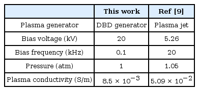
Comparison of modeled He plasma conductivity
V. Conclusion
In this work, the attenuation of plasma is investigated in the Ka-band. The attenuation due to plasma is measured under various gas and pressure conditions. Attenuation as high as 9.0 dB/m is obtained in the measured range. Helium plasma shows the highest attenuation effect, while air, which is composed mostly of reactive gases such as nitrogen and oxygen, is the least effective. All three tested gas environments (He, Ar, and air) showed higher attenuation at higher pressures. Based on the measured results, the plasma is electromagnetically modeled with conductivity. Results show that the He plasma has higher conductivity compared to other gases and that the difference in conductivities is maximized at 1 atm. Utilization of various gas plasmas to control RCS remains as future work.
Acknowledgments
This work has been supported by the Low Observable Technology Research Center program of the Defense Acquisition Program Administration and Agency for Defense Development.
References
Biography

Joo Hwan Lee was born in Seoul, Korea, in 1991. He received a B.S. degree in information and communication engineering from Sejong University, Seoul, Korea, in 2016, and is currently working toward an M.S. degree in electrical and electronic engineering at Yonsei University. His current research interests include low-observable applications based on plasma.

Sangin Kim received a B.S. degree in electrical and electronic engineering from Yonsei Universtiy, Seoul, Korea, in 2015 and is currently working toward a Ph.D. degree in electrical and electronic engineering at Yonsei University. His current research interests are plasma analysis, HEMP, EM shielding analysis, vital sign sensors, and RF systems. Recent research focuses on electric problems caused by HEMP.

Joonsuk Kim was born in Seoul, Korea. He received B.S. and Ph.D. degrees from Yonsei University, Seoul, in 2009 and 2017, respectively. His current research interest is passive circuitry for microwave applications.

Doo-Soo Kim was born in Kwangju, Korea. He received a B.S. degree from Sogang University, Seoul, Korea, in 2001, and an M.S. degree in electrical and electronic engineering from POSTECH, Pohang, Korea in 2006. Currently he works for Agency for Defense Development (ADD), Daejeon, Korea, as a senior researcher. His current research interests include active phased array antenna systems and optimization algorithms.

Yuna Kim received her B.S. degree in electrical and electronic engineering from Yonsei University, Seoul, Korea, in 2012. She is currently working toward her Ph.D. degree in electrical and electronic engineering at Yonsei University. Her current research interests are plasma analysis, HEMP coupling, and numerical analysis based on multi-physics including thermodynamics and electromagnetics. Her recent research focuses on electric problems caused by high temperatures in a circuit.

Yongshik Lee was born in Seoul, Korea. He received a B.S. degree from Yonsei University, Seoul, Korea, in 1998, and M.S. and Ph.D. degrees in electrical engineering from The University of Michigan, Ann Arbor, MI, in 2001 and 2004, respectively. In 2004, he was a postdoctoral research associate at Purdue University, West Lafayette, IN. From 2004 until 2005, he was with EMAG Technologies Inc., Ann Arbor, MI, as a Research Engineer. In September 2005, he joined Yonsei University, Seoul, Korea, where he is currently a professor. His current research interests include wireless power transfer, plasma-based electromagnetic cloak, electromagnetic metamaterials, and microwave and millimeter-wave engineering for communications applications.

Jong-Gwan Yook was born in Seoul, South Korea. He received B.S. and M.S. degrees in electronics engineering from Yonsei University, Seoul, Korea, in 1987 and 1989, respectively, and a Ph.D. degree from the University of Michigan, Ann Arbor, in 1996. Currently, he is a professor with the School of Electrical and Electronic Engineering, Yonsei University, Seoul, Korea. His main research interests are in the areas of theoretical/numerical electromagnetic modeling and characterization of microwave/millimeter-wave circuits and components, design of radio frequency integrated circuits and monolithic microwave integrated circuits, and analysis and optimization of high-frequency high-speed interconnects, including signal/power integrity, based on frequency as well as time-domain full-wave methods. Recently, his research team has developed various biosensors, such as carbon nanotube RF biosensors for nanometer sized antigen-antibody detection as well as remote wireless vital signal monitoring sensors.