A Wide Dual-Band Metamaterial-Loaded Antenna for Wireless Applications
Article information
Abstract
A compact, wide dual-band antenna designed to resonate at 2.25 GHz and 5.4 GHz is proposed in this paper. The proposed antenna is a monopole rectangular patch designed to operate at 5 GHz. This basic structure is modified by introducing a metamaterial-based interdigital capacitor reactive loading that exhibits dual-band characteristics at 2.25 GHz and 5.4 GHz. A bandwidth greater than 1.4 GHz at the two resonant frequencies is obtained. The compact size of the proposed antenna is 0.0989λ0 × 0.0498λ0, where λ0 is calculated at the first resonance. The antenna is etched on a FR4 substrate with dielectric constant ɛr = 4.4 and thickness of 1.6 mm. The simulated results exhibit considerable gain and wide impedance bandwidth at the resonant frequencies. Monopole-like radiation patterns are obtained at both the operating frequencies. The designed antenna can be applied in wireless local area networks and Wi-MAX wireless communications.
I. Introduction
As the demand for the antennas in several wireless applications, such as Wi-Fi, Wi-MAX, and wireless local area network (WLAN), is increasing rapidly, there is an urgent need for multi-band-operated antennas that are manufactured at low-cost and smaller in size. This multi-band performance can be achieved using several techniques such as slots [1], fractals [2], various feeding techniques [3–6], and reactively loading the monopole antennas [7]. The use of metamaterial (MTM) loading in antennas has emerged because of its unique characteristics. MTMs possess a simultaneously negative electric permittivity (ɛ) and magnetic permeability (μ), and thus, a negative refractive index (NRI), which gives them some superior characteristics compared with conventional antennas. Mu-negative MTMs have negative magnetic permeability and are called left-handed materials [8] according to Veselago [9]. Although these materials are not found in nature, their properties can be obtained from their structures rather than their composition.
One of the methods of obtaining NRI, as discussed by Eleftheriades et al. [10], is based on reactively loaded transmission lines. The advantages of using MTM structures are as follows: (1) beam squint at a particular frequency can be reduced by using MTM loading [11], and (2) NRI provides excitation in the phase for all the monopoles, in a four-element array [12, 13].
A design approach for MTM loading called the mesh-grid approach, which is built on a ceramic substrate, is proposed in [14], and a unidirectional loop antenna loaded with μ-negative MMT unit-cells and arc-shaped directors is presented in [15]. The introduction of a gap between transmission conductors and vias to obtain inductive and capacitive loading is presented in [16]. In this paper, an L-shaped slot antenna with MTM reactive loading is introduced for WLAN and Wi-MAX applications. It is based on a single MTM unit cell integrated into the monopole. In this monopole mode, the ground plane does not act as a radiator and thus the effective radiating area decreases to a large extent.
In this letter, a micro-strip fed monopole antenna for 2.5 GHz Wi-MAX, 5 GHz and 5.9 GHz WLAN applications are proposed. With the aid of MTM-inspired reactive loading and interdigital capacitance (IDC), the antenna effectively covers the required frequency bands for WLAN and Wi-MAX applications. Section II describes the geometrical structure of the proposed antenna, and Section III presents the results and discussions. Section IV that concludes the paper with the inclusion of possible wireless applications.
II. Antenna Design
The design of the proposed antenna is illustrated in Fig. 1. The antenna has a monopole with an inverted L-slot and an IDC above the inverted L-slot. It is designed on an FR4 substrate with a relative permittivity ɛr = 4.4, loss tangent of 0.02, and thickness of 1.6 mm. The High Frequency Structure simulator (HFSS ver. 17.0) is used to simulate and optimize the designed antenna.
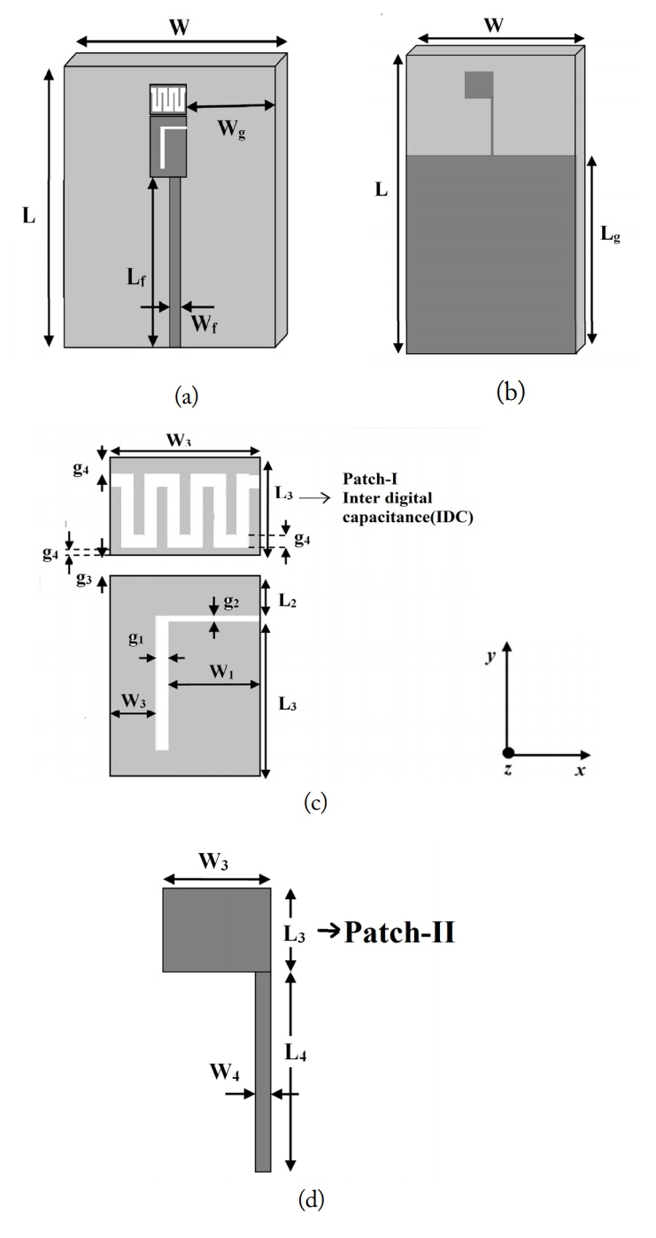
Geometrical configuration of the proposed MTM antenna (Ant 4): (a) top view, (b) bottom view, (c) dimensions of the top view in detail, and (d) dimensions of the bottom view in detail.
The evolution of the designed antenna is presented in Fig. 2. Ant 1 has a basic monopole structure, Ant 2 has a monopole with an inverted an L-slot, Ant 3 has a rectangular patch on top of the monopole, and, the proposed antenna, Ant 4, is modified by introduction of a meander structure on top of the monopole. The basic monopole is designed to resonate at 5.0 GHz. The insertion of the L-slot produces a second resonance at 3.2 GHz in addition to 5.1 GHz. By adding the rectangular patch above the monopole, Ant 3 introduces an additional frequency of 2.4 GHz. A wide-band characteristic is observed in the third resonant band. Ant 4 resonates at 2.3 GHz and 5.26 GHz as shown in Fig. 1(c), producing an additional resonant frequency at 6.0 GHz in the same wide bandwidth as Ant 3.
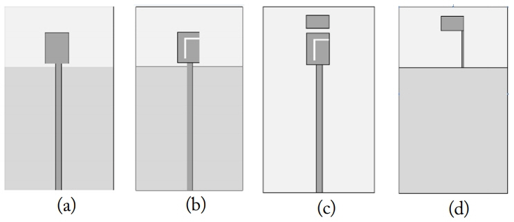
Design evolution of the proposed antenna: (a) monopole antenna (Ant 1), (b) monopole with inverted L-slot (Ant 2), (c) a rectangular patch introduced to (b) (Ant 3), and (d) ground plate of (a), (b), and (c).
The proposed antenna consists of a 6.5 mm × 8.5 mm rectangular patch with an inverted L-shaped slot inserted into it as shown in Fig. 2. A top rectangular patch (Patch I) with a size of 6.5 mm × 4 mm placed above the basic rectangular patch at a gap distance of 0.4 mm and a bottom rectangular patch (Patch II) with the same size placed on the ground plane along with a thin strip are added to the basic structure to produce a resonance at 2.3 GHz and 5.2 GHz.
Series capacitance is formed between Patch I and Patch II. Shunt inductance is formed by the thin short-circuited strip constituting the single-cell, MTM-inspired reactive load, the produced resonance of which is 2.3 GHz and 5.2 GHz.
A meander line-shaped slot is etched on Patch I similar to the IDC, to produce the final proposed antenna structure (Ant 4) as shown in Fig. 1. The original frequencies centered at 2.4 GHz and 5.6 GHz are maintained by covering the 2.3/2.4 GHz Wi-Fi and 5.2/5.8 GHz WLAN bands. The resonance produced by the inverted-L slot at around 3.1 GHz merges with the 2.3 GHz band, resulting in a wide bandwidth from 2.1 GHz to 3.6 GHz. An additional resonance at around 6 GHz occurs, again resulting in a wide bandwidth from 4.96 GHz to 6.4 GHz.
The geometry of the proposed antenna is illustrated in Fig. 1. The antenna is a single MTM cell with reactive loading. Its overall area covering the ground plane is 40 mm × 45 mm, and the radiation element area is 12.9 mm × 6.5 mm. A 50-Ω transmission line, a monopole with an inverted-L slot, and a rectangular patch (Patch I) as an IDC are placed on the top of the substrate, and a second rectangular patch (Patch II) and a short-circuited inductive strip are located on the bottom side of the substrate, producing the inductive reactive loading. Patch I and Patch II collectively produce a capacitor-like effect.
A capacitive reactive loading is created by an equivalent meander-shaped IDC. This capacitor effect is observed between rectangular Patch I on the ground plane and rectangular Patch II on the top side of the substrate. The optimized dimensions of the antenna are as follows (in mm): W = 40, L = 45, Lf = Lg = 30, Wf = 1.9, Wg = 18, W1 = 4, W2 = 2, W3 = 6.5, W4 = 0.3, L1 = 7, L2 = 1.3, L3 = 4, L4 = 8.9, g1 = g4 = 0.5, g2 = 0.2, g3 = 0.4, and d = 1.5.
III. Simulated Results and Discussions
To analyze the performance of the antenna, the results are obtained by simulating the design in HFSS ver.17.0. The results are as follows.
1. Frequency Characteristics
To understand the frequency characteristics of the proposed antenna, the return loss and current distributions are observed and presented below.
Return Loss: Fig. 3 shows the reflection coefficients of the proposed antenna in comparison with other antennas shown in Fig. 2. Fig. 4 presents the simulated return loss of the proposed antenna. The simulated return loss is presented in Fig. 4. The simulated antenna presents a −10 dB impedance bandwidth of 1.41 GHz from 2.1 GHz to 3.6 GHz (60.63%) and 1.46 GHz from 4.96 to 6.0 GHz (27.18%) covering the WLAN and Wi-MAX applications.
Current Distribution: To obtain a deep insight into the working principle of the proposed antenna, the current distributions of the antenna at 2.4, 3.06, 5.2, and 6.0 GHz are presented in Fig. 5. The figure shows that the currents at 6 GHz mainly concentrate on the Patch I, those at 3.06 GHz, radiate from a longer branch of the monopole to the center of the monopole, and those at 5.26 GHz shift to the shorter monopole. At 2.33 GHz, the waves reach the MTM loading through the EM coupling, thus forming an energy loop and enabling effective radiation.
Radiation Pattern: The simulated radiation patterns in the elevation (xz- and yz-planes) and azimuth (xy-plane) planes are shown in Fig. 6. Fig. 7 illustrates the simulated 3D radiation pattern plots of the proposed antenna. An omnidirectional radiation pattern is obtained in the xy-plane at the dominant resonant frequency band. As the resonant frequencies increase, the radiation patterns change because of the effects of high-order modes.

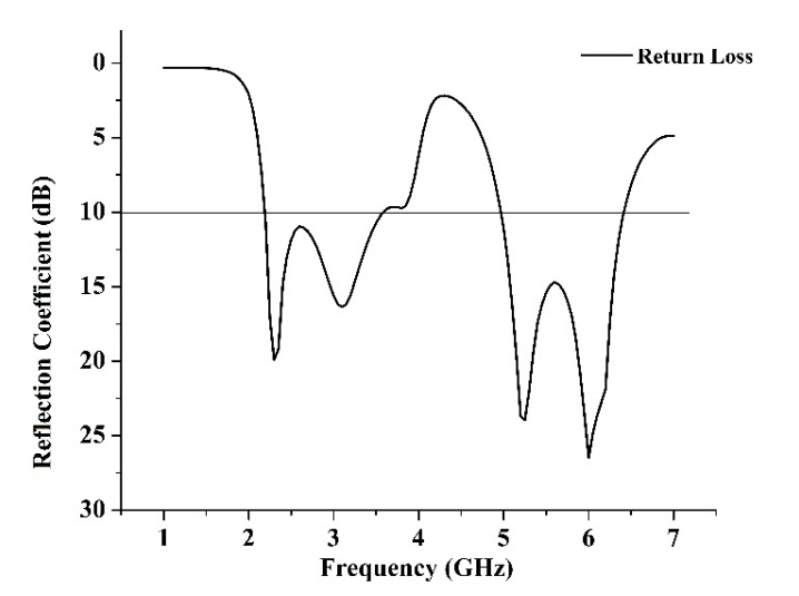
Reflection coefficient of the proposed antenna.

Surface current distributions at (a) 2.33 GHz (top view), (b) 2.33 GHz (bottom view), (c) 3.06 GHz (top view), (d) 3.06 GHz (bottom view), (e) 5.26 GHz (top view), (f) 5.26 GHz (bottom view), (g) 6 GHz (top view), and (h) 6 GHz (bottom view).
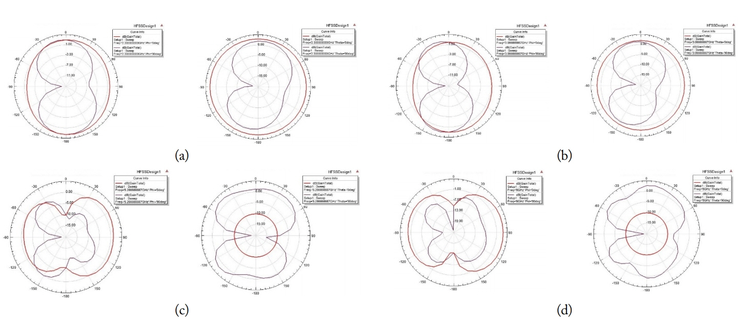
Simulated radiation patterns in the elevation plane (left side) and azimuth plane (right side) at 2.33 GHz (a), 3.06 GHz (b), 5.26 GHz (c), and 6.0 GHz (d).
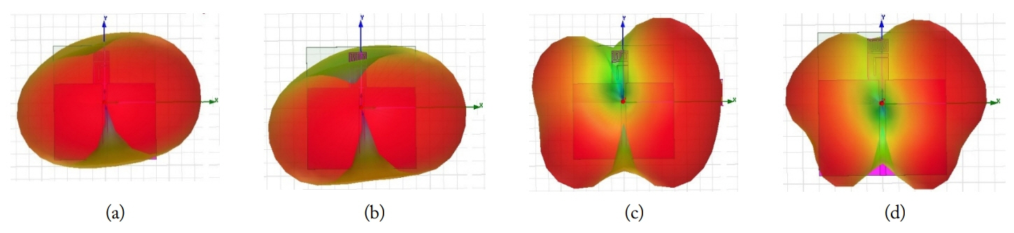
Simulated 3D radiation patterns at 2.33 GHz (a), 3.06 GHz (b), 5.26 GHz (c), and 6.0 GHz (d).
2. Measured Results
To measure the performance of the proposed antenna, the prototype is fabricated, and the results are obtained. Fig. 8 shows a photograph of the prototype.
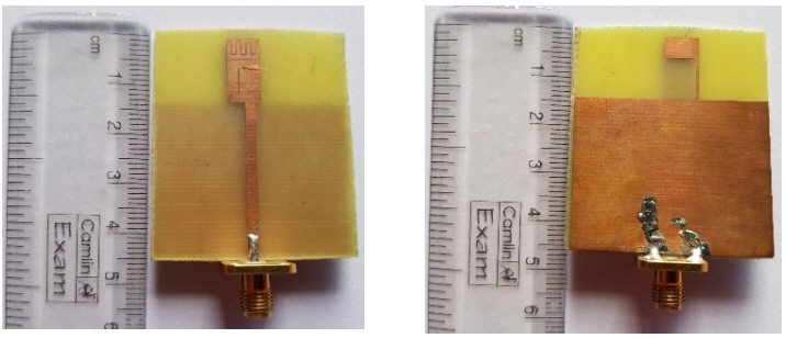
Photograph of the fabricated MTM-loaded antenna.
2.1 Return loss
The measured return loss is depicted in Fig. 9. A −10 dB impedance band of 1.8 GHz (2.1–3.9 GHz, 80.3%) and 1.4 GHz (5.01–6.4 GHz, 26.4%) is observed. The variations between the simulated and measured return losses are presented in Figs. 4 and 7. These variations may have due to fabrication imperfections, substrate losses, and measurement circumstances. The measurements are performed using the Agilent N5230A Network Analyzer.
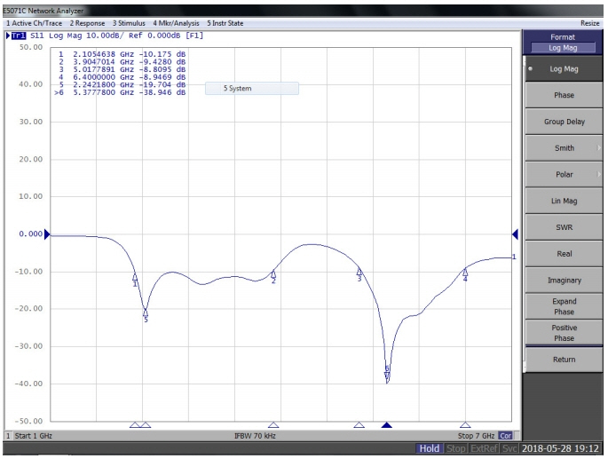
Measured return loss of the proposed MTM-loaded antenna.
2.2 Radiation characteristics
To understand the measured radiation characteristics of the proposed antenna, the radiation patterns and gain plots are plotted and shown in Figs. 10 and 11.
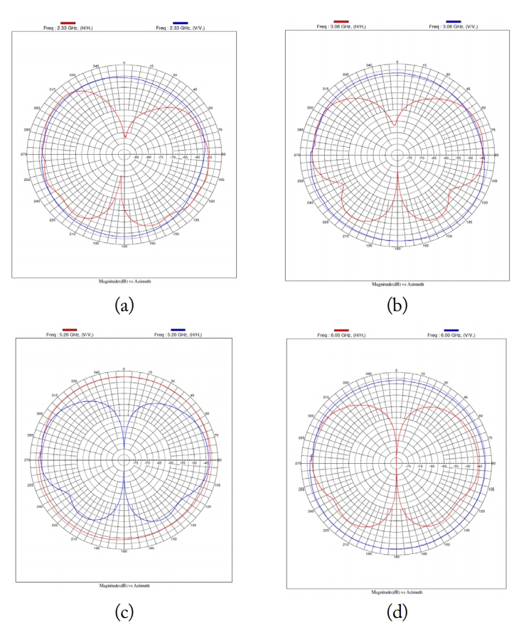
Measured radiation pattern of the proposed antenna. Azimuthal radiation pattern (in the xy-plane) at 2.33 GHz (a), 3.06 GHz (b), 5.26 GHz (c), and 6.0 GHz (d).

Simulated gain compared with the measured gain.
Radiation pattern: Fig. 10(a)–(d) show the measured azimuthal plots in the horizontal and vertical planes of the designed antenna at 2.33, 3.06, 5.26, and 6.0 GHz.
Gain: Fig. 11 presents the gain versus frequency graph of the proposed MTM-loaded antenna. The simulated gain is above 2 dB over the entire −10 dB impedance bandwidth, satisfying the minimum gain condition for using the antenna for commercial applications such as WLAN and Wi-MAX.
This study is compared with some of the dual band works in the literature, and the comparison is presented in Table 1. As shown in Table 1, a wide impedance bandwidth is achieved with a small radiating element occupying a lesser area compared with the existing multiband antennas.
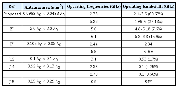
Comparison of the proposed work
IV. Conclusion
A dual-band, MTM-loaded antenna with a wideband characteristic is designed and analyzed in this paper. The developed antenna resonates at 2.25 GHz, which includes 3.06 GHz resonance, and 5.37 GHz, which includes 6 GHz, thus forming a wide band with a −10 dB impedance bandwidth of 80.3% and 26.4% at the first and second resonant frequencies, respectively. The proposed antenna exhibits a dipole-like (figure-eight shape) radiation pattern in 2D planes with a maximum gain of 3.5 dB at 2.3 GHz, and a good gain of above 2 dB is observed at the remaining frequencies (except 6.0 GHz). The advantage of the MMT loading on the basic rectangular patch in obtaining a wide impedance bandwidth of 80.3% is clearly demonstrated in this paper. The proposed antenna fulfills the bandwidth requirements of commercial wireless applications, such as IEEE 802.11 WLAN 2.4 GHz (2.4–2.484 GHz), 5 GHz (5.15–5.35 GHz/5.725–5.825 GHz), IEEE 802.16 Wi-MAX 2.5 GHz (2.5–2.69 GHz), and 3.5/5.5 GHz Wi-MAX (3.4–3.69 GHz, 5.25–5.85 GHz) applications.
References
Biography

Sulakshana Chilukuri received her bachelor’s degree in electronics and communication engineering from the G. Narayanamma Institute of Technology and Science, Hyderabad, India, in 2007, her master’s degree in electronics and communication engineering with communication systems specialization from the National Institute of Technology, Tiruchirappalli, Tamilnadu, India, in 2010, and her Ph.D. in electronics and communication engineering from the National Institute of Technology Warangal, Telengana, India, in 2016. She worked as a post-doc research fellow at the University of West of Scotland, UK, in 2017. From 2015 to 2016, she worked as an assistant professor at the G. Narayanamma Institute of Technology and Science, Hyderabad, India. She is currently working as an associate professor in Vardhaman College of Engineering. Her field of study is reconfigurable antennas, and her other areas of interest are microwave engineering, electromagnetics and transmission lines, wireless communication systems, and MIMO antennas. She has published her works in 11 peer-reviewed international journals, and 20 international conferences.

Srividya Gundappagari graduated from the Vardhaman College of Engineering, Hyderabad, India in 2018. Her areas of interests include antennas and microwave engineering. She has presented a paper in the IEEE Indian Conference on Antenna and Propagation - 2018 held in Hyderabad, India.