Optically Transparent Patch Antennas Using Saltwater for WLAN Applications
Article information
Abstract
This paper presents the design, fabrication, and measurement of a novel transparent patch antenna using saltwater with high-optical-transparency applications for wireless local area networks (WLANs) at 2.4–2.5 GHz. The most important reason for using saltwater for transparent antenna applications is its superior average optical transparency (OTav >90%) compared to other typical transparent electrodes, such as indium tin oxide (ITO; OTav >80%) or metal-mesh film (MMF; OTav >60%). This study designs three types of antennas: an antenna with a conductive part made of copper sheet (CS) for both the radiator and ground plane (case 1) to compare the performance with two types of proposed transparent antennas that use saltwater as the conductive parts; an antenna with saltwater for the radiator and MMF for the ground plane (case 2); and an antenna with saltwater for both the radiator and ground plane (case 3). The case 1, case 2, and case 3 antennas have peak gains of 6.87, 4.4, and 1.91 dB, respectively, and have corresponding radiation efficiencies of 93.5%, 62%, and 34%. To the best of our knowledge, this is the first demonstration of a transparent patch antenna using saltwater.
I. Introduction
Currently, optically transparent antennas applications are considerably attractive not only in both theoretical researches but also in practical applications owing to their transparency [1, 2]. The existing optical transparent antennas generally have solid metallic transparent electrodes (TEs) [3–10]. The wireless local area network (WLAN) band is one of the bands that is becoming increasingly popular with transparency-related studies and practical applications. The National Aeronautics and Space Administration (NASA) created a transparent microstrip patch antenna using AgHT-8 as a conductive coating [4]. A transparent microstrip patch antenna made of fluorine-doped tin oxide showed low efficiency [5]. Additionally, many types of transparent conductive films use widely studied solid materials, such as indium tin oxide [6], graphene [7], AgHT-4 [8], or a metal mesh [9, 10]. Indium tin oxide has a crystalline structure and therefore becomes brittle. It has a high sheet resistance of 7 Ω/sq, and it is expensive due to the cost of the rare-earth indium component [6]. The sheet resistance of graphene is extremely high, leading to poor performance in transparent antenna applications [7]. In our previous work, we designed and analyzed the performance of a transparent patch antenna with a metal mesh using a metal-mesh film (MMF) [10] and a multilayer film [10]. However, in another study [10], a microchip patch antenna made of MMF (copper) and multilayer film (IZTO/Ag/IZTO) showed relatively low average optical transparency (OTav <68 %) in the visible light band from 400 to 700 nm. Therefore, antennas constructed with such TEs are inefficient, which is one of the most significant barriers preventing the widespread use of transparent antennas.
Currently, owing to its excellent average optical transparency (OTav >95%, salinity level of 40 parts-per thousand [ppt]), widespread accessibility, and low fabrication cost, saltwater (SW) has been investigated as a viable option for developing a new field of high-transparent antennas. The conductive part of a transparent antenna is SW, which carries electric charges in the form of ionic particles. Thus far, many types of SW antennas have been studied and fabricated [11–14]. In one study [12], a high-efficiency sea-water monopole with an average radiation efficiency of 60% across a frequency range of 40–200 MHz was suggested for marine wireless communications. Another sea-water monopole, in one of our studies [13], introduces a sea-water monopole antenna with high radiation efficiency for WLAN applications. In both cases [12, 13], the performance of the antenna was analyzed by dissolving salt in pure water. In another work [14], we demonstrated a dipole antenna using SW with great optical transparency. Therefore, monopole and dipole antennas with a radiated path using SW have been fabricated, and their performance capabilities have been determined experimentally [12–14]. However, the SW has much lower conductivity compared to metal; therefore, to decrease the ohmic loss and increase the radiation efficiency, most existing transparent SW antennas use a cylindrical shape [12, 13].
In this paper, we present optically transparent patch antennas with high optical transparency with SW as a transparent conductive liquid for WLAN bands between 2.4 and 2.5 GHz. A conventional patch antenna (case 1) is designed for a performance comparison with two types of proposed antennas. The proposed transparent patch antennas are fabricated as case 2 and case 3, using the same radiator component of the SW; however, they use different types of ground planes of the MMF and SW. On the other hand, given the high sheet resistance of SW, to improve the performance of the SW antenna, a thin metal strip was put onto a feed probe to increase the excitation and enhance the radiation efficiency, which does not affect the transparency of the antenna in cases 2 and 3. For a detailed comparison of the performance capabilities of the antenna, its gain, radiation efficiency, and transparency of the TEs are measured.
II. Antenna Design and Fabrication
1. Dimensions and Structure of the Patch Antenna
Fig. 1 shows the structure and dimensions of the proposed microstrip patch antennas. The antennas are configured so that the top is the conductive radiator, represented by blue color, and the bottom is the conductive ground, represented by green color. There are acryl substrates represented by the gray color between these two conductive parts. There are three types of antennas: case 1, case 2, and case 3, each using CS/CS, SW/MMF, SW/SW as conductive radiator/ground parts (Table 1). The conductive part, CS, is a copper sheet coated with 18 μm thick copper [10], and the SW is realized by containing salt water (salinity 200 ppt) in a thin transparent acrylic plate with a thickness (Wrl) of 1 mm. Another conductive part, MMF, is implemented with a square metal mesh (200 μm × 200 μm) using a 21-μm wide copper wire on a thin polyethylene terephthalate film (thickness 100 μm) [1]. In addition, the outer part of the radiator using the SW of cases 2 and 3 was made by attaching a thin metal strip (thickness, tp = 18 μm; width, hp = 5 mm) to the acrylic plate to improve antenna performance. Moreover, the signal line of the RF connector was connected to this metal strip of the radiator. The thickness of the ground (tg) varies depending on the material used in CS (tg = 18 μm), MMF (tg = 105 μm), and SW (tg = 5 mm). The detailed dimensions of the proposed antennas are shown in Table 2. The substrate used for all antennas is clear acrylic (ɛr = 2.8, tanδ = 0.008). The thickness (hs) of the acryl is 20 mm with dimensions of Ws × Ls = 50 mm × 50 mm.
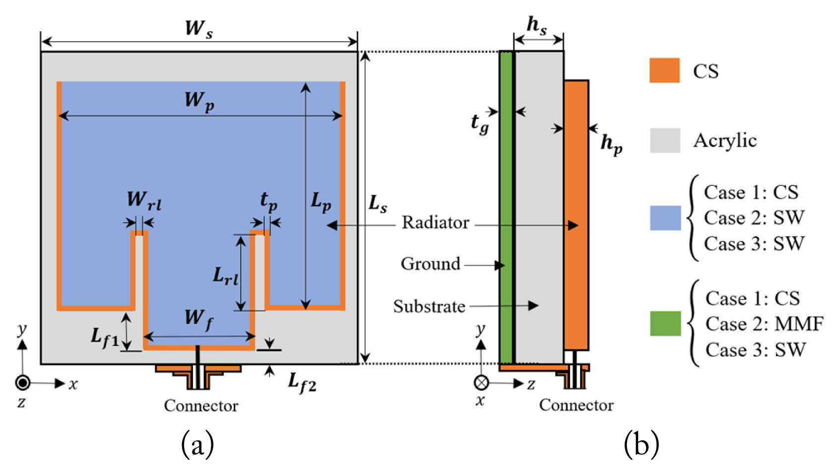
Dimensions of the patch antenna: (a) top view and (b) side view.

Composition of antennas

Dimensions of the proposed transparent patch antenna
The dimensions of the patch antenna are determined by the width (Wp) and length (Lp) with Wp × Lp = 44 mm × 33 mm to have a fundamental resonance frequency at 2.45 GHz. The impedance matching of the input feeding line is 50 Ω, the feeding line’s width and length are correspondingly Wf × Lf1 = 24 mm × 6.5 mm, and the distance from the input edge is Lf2 = 0.5 mm. In addition, the recessed lines starting from both sides of the input feeding line are used for better impedance matching. All antennas use recessed lines of the same size with Wrl × Lrl = 1 mm × 13 mm. In addition, the thickness of the radiator part (hp) for the proposed antenna varied from 18 μm (case 1) to 5 mm (case 2, case 3).
2. Electrical and Optical Analyses of Saltwater
The salt water used in this article is made from common salt dissolved with purified water at room temperature by the following two steps: (1) pour 100 mL purified water into a 300 mL glass beaker; (2) add ms gram salt to the beaker and stir until dissolved. The salinity of SW (S) is determined through the amount of salt added to the glass beaker: S = 1000ms/(100 + ms), where ms is the amount of salt in grams, and S is the salinity of the SW solution in ppt [15].
Fig. 2(a) displays the measured conductivity and optical transparency (OT) of SW with different salinities generally ranging from 35 to 200 ppt at room temperature. In fact, both the electrical conductivity and permittivity of SW depending on temperature and frequency were carefully studied. However, when salinity exceeds 50 ppt, conductivity is almost constant with frequency [16]. The conductivity of salt water is 5, 10, and 20 S/m, corresponding to salinities of 35, 80, and 200 ppt, respectively. Fig. 2(b) shows the measured OT of Acrylic/SW/Acrylic (ASA) in the visible wavelength to investigate the OT for varying conductivity. The OT is higher than 90% and increases with decreasing conductivity. The electrical conductivity of the SW was measured using a multi-range conductivity meter (HI-8633) by dissolving salt in pure water. The optical transparency of the proposed antennas was determined using a UV-visible spectro-photometer (T60 model) connected to a computer. In Fig. 2(a), the electrical conductivity of SW increases even as the salinity level increases, and the transparency of the SW decreases slightly. It is also important to note that, at room temperature, the highest salinity of SW is 263 ppt. Due to the higher ohmic loss of a liquid antenna, it typically has a lower radiation efficiency than a typical metal antenna. For the proposed antenna design with SW as a conductive substance, we selected a salinity level of 200 ppt to ensure that the antenna’s ohmic loss was reduced and its stability was maintained over time. SW has an effective conductivity of 20 S/m and an extremely high OT at 91% with 200 ppt salinity.
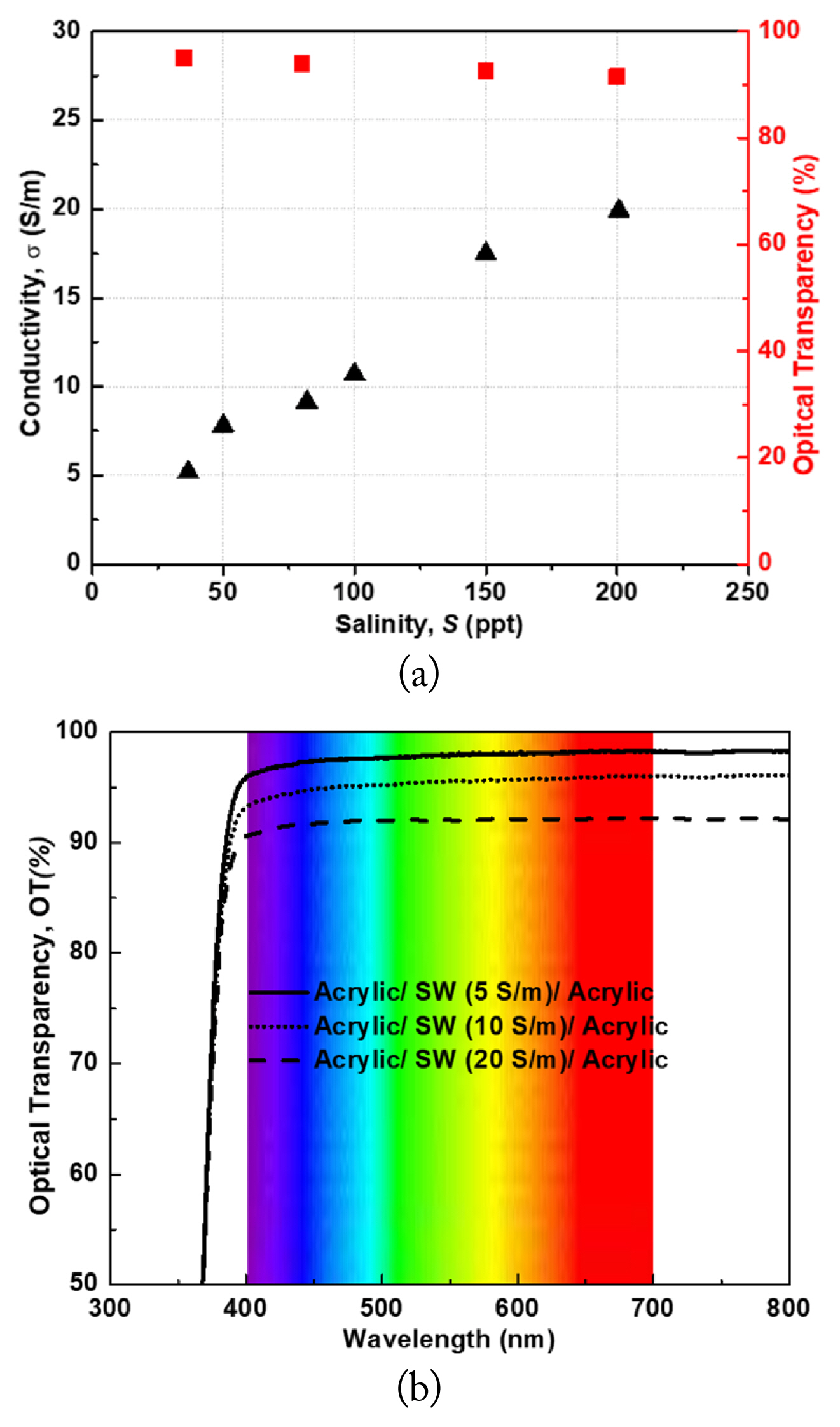
(a) Measured conductivity and OT of the saltwater. (b) Measured OT of Acrylic/SW/Acrylic (ASA) in the visible wavelength.
III. Simulation and Measurement Results of the Antenna
The simulated and measured results of the reflection coefficients (S11) of patch antennas with different conductive parts covering the center frequency for WLAN band (2.4–2.5 GHz) applications are shown in Fig. 3. The measured (S11) was evaluated using a network analyzer (E5071B), and the measured results were found to be in good agreement with the simulation results. The reflection coefficient measurement (S11) shows good agreement with the simulation; there is less change in the bandwidth when changing the conductive component. Therefore, the results (S11) of the three cases demonstrate a −6 dB bandwidth ranging from 2.25 to 2.6 GHz (of 350 MHz; 14%). Cases 1 and 2 show similar reflection coefficients and good impedance matching over the observed frequency range. However, case 3 exhibits losses in the measured frequency band, as it has a ground plane using SW, and SW has a higher sheet resistance than CS (case 1) and MMF (case 2) as a ground plane.

Simulation and measurement results of the reflection coefficients (S11): (a) case 1, (b) case 2, and (c) case 3.
Fig. 4(a) shows the measurement setup of the fabricated antenna in an anechoic chamber. The inset photo in Fig. 4(a) depicts the fabricated optical transparent patch antenna using only SW (case 3) as a conductive part. The fabricated patch antennas are depicted in Fig. 4(b), which demonstrates an actual photo of the fabricated antenna over text, displaying extremely high optical transparency for case 2 and case 3 antennas. We observed that the fabricated antennas retained a high level of transparency.

(a) Measurement setup of the transparent antenna in an anechoic chamber. (b) Fabricated patch antennas over text.
The measured optical transparency (T) of the antenna structure can be explained using the Fresnel formulas [17]:
where the refractive indexes of mediums 1 and 2 are denoted by n1 and n2, respectively; the angles of incidence and refraction are represented by γ1 and γ2 when the incident wave comes from medium 1 to 2.
When the incident wave is coming from a normal direction (the same conditions as the measurement), thus, γ1 = γ2 = 0. The refractive indexes of SW (conductivity 20 S/m) and acrylic (at wavelength 600 nm) are 1.37 and 1.5, respectively [15]. The average transmittance in the visible light band and sheet resistance of MMF is 62.1% and 0.18 Ω/sq, respectively [10]. The calculated OT of the antenna in case 3 (OTav >91%) is higher compared to that in case 2 (OTav >60%) because the case 3 antenna uses SW as the radiator and ground part. The measured result is slightly lower than the calculated result due to the imperfect measurement.
Fig. 5 depicts the simulated and measured results of the gain and total radiation efficiency of the antenna. The measurement results of the three antenna types show good agreement with the simulation results. The antennas in case 1, case 2, and case 3 have peak gains of 6.87 dBi, 4.4 dBi, and 1.91 dBi, respectively, and a corresponding total radiation efficiency of 93.5%, 62.8%, and 34% at the center frequency of the WLAN band (2.45 GHz). As expected, case 1, which consists of a CS, has the strongest gain and total radiation efficiency of the three different types of antennas. In addition, case 2 shows higher antenna performance in terms of the gain and radiation efficiency than the case 3 antenna, given that SW has high sheet resistance compared to MMF. Sheet resistance is dependent on material conductivity, which impacts antenna losses. These results demonstrate the significance of sheet resistance when using TEs for antennas.
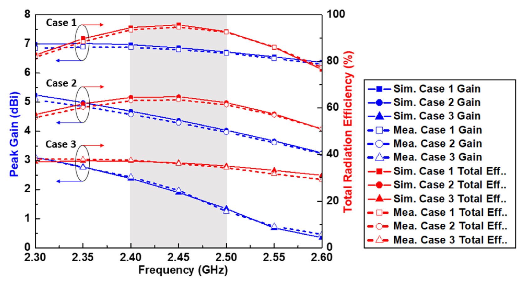
Simulation and measurement results of the gain and radiation efficiency of the proposed antennas.
The simulated and measured far-field radiation patterns of antennas with different conductive part configurations are depicted in Fig. 6. The radiation pattern is measured at a center frequency at 2.45 GHz of the WLAN service band. The radiation patterns of the proposed antennas are in good agreement with the simulated results. In Fig. 6(a), all three configurations exhibit directional radiation characteristics on the yz-planes. However, case 2 and case 3 use conductive components at the ground as MMF and SW, respectively; the conductivity of MMF and SW are lower than CS; therefore, there is a small difference between the back lobes of the proposed antenna (cases 2, 3) with case 1.
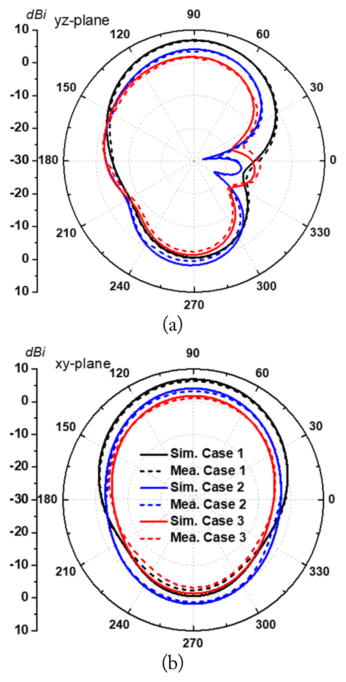
Simulation and measurement results of the radiation patterns at 2.45 GHz: (a) yz-planes and (b) xy-planes.
Table 3 compares the performance of the proposed SW patch antenna to that of the transparent patch antennas reported thus far. All the antennas listed in Table 3 are patch antennas with basic parameters listed as percentage frequency bandwidth (FB) with a −6 dB bandwidth, gain, radiated efficiency, and OT. The conductive parts used to design the transparent antennas are fluorine-doped tin oxide (FTO) [5], AgHT-4 [8], a wire metal mesh (WMM) [9], MMF (copper) [10], multilayer film (MLF; IZTO/Ag/IZTO) [10], and water [18], represented as solid TEs. As shown in Table 3, the proposed antenna shows more improvements than the antennas with solid TEs in the gain, radiated efficiency, and OT.

Performance comparison of the proposed antenna with the transparent patch antennas in previous works
IV. Conclusion
This study presented transparent patch antennas that use SW and have high OT for applications on the WLAN band. Three types of antennas were studied based on the component changes of the conductive radiator/ground parts: CS/CS (case 1), SW/MMF (case 2), and SW/SW (case 3). The measurement results reveal that the proposed antennas in case 2 and case 3 have gains of up to 4.4 dBi and 1.91 dBi, respectively, and maintain corresponding high transparency levels exceeding 91% and 60% in the visible light band. The material property of the MMF has lower sheet resistance than SW; therefore, the antenna with MMF used as a ground plane (case 2) shows higher antenna performance in terms of the gain and radiation efficiency than the antenna using SW as a ground plane (case 3). In contrast, SW has higher OT than MMF. In terms of efficiency, the case 2 antenna showed superior performance compared to the conventional transparent antennas. This study, given that research on different materials from transparent electrodes is extremely significant to improve the optical and performance capabilities of transparent antennas, will be attractive in the near future to ensure the production of high-quality transparent devices.
Acknowledgments
This study was supported by the Research Program funded by Seoul National University of Science and Technology.
References
Biography

Tien Dat Nguyen received his B.S. degree in electrical and electronics engineering from Hanoi University of Science & Technology (HUST), Hanoi, Vietnam, in 2020. He is currently pursuing the M.S. degree with Department of Graduate School of Nano IT Design Fusion at Seoul National University of Science and Technology, Seoul, South Korea. His research interests include filters and transparent antennas.

Jung Han Choi received his B.S. and M.S. degrees in Electrical Engineering from the Sogang University, Seoul, Korea, in 1999 and 2001, respectively, and a Dr.–Ing. degree from the Technische Universität München, Munich, Germany in 2004. From 2001 to 2004, he was a research scientist in the Institute for High-Frequency Engineering at the Technische Universität München, Germany. During this time, he worked on high-speed device modeling and circuit development for high-speed optical communications. From 2005 to 2011, he was with the Samsung Advanced Institute of Technology and the Samsung Digital Media & Communication Research Center, where he worked on RF bio sensors, nano device modeling, and circuit design for millimeterwave applications, including 60 GHz CMOS. In 2011, he joined the Fraunhofer Institute (Heinrich-Hertz Institute), Berlin, Germany as a senior researcher. His current research interests include active/passive device design and their modeling, high-frequency circuit design, and metamaterials.

Chang Won Jung received a B.S. degree in radio science and engineering from Kwangwoon University, Seoul, South Korea, in 1997; an M.S. degree in electrical engineering from the University of Southern California, Los Angeles, CA, USA, in 2001; and a Ph.D. in electrical engineering and computer science from the University of California at Irvine, Irvine, CA, USA, in 2005. He was a research engineer with the Wireless Communication Department, LG Information and Telecommunication, Seoul, South Korea, from 1997 to 1999. From 2005 to 2008, he was a senior research engineer with the Communication Laboratory, Samsung Advanced Institute of Technology, Suwon, South Korea. Since 2008, he has been a professor with the Graduate School of Nano-IT Design Technology, Seoul National University of Science and Technology, Seoul, Korea. His current research interests include antennas for multi-mode multi-band communication systems, multifunctional reconfigurable antennas, electromagnetic interference, millimeterwave applications, optically transparent electrodes, and wireless power transfer for energy harvesting, etc.