Free-Space Two-Tier One-Port Calibration Using a Planar Offset Short for Material Measurement
Article information
Abstract
The scattering parameters of a material under test (MUT) are prerequisites for characterizing the material parameters of the MUT. This paper describes a free-space two-tier one-port calibration method using a planar offset short as a free-space calculable reflect standard for measuring the scattering parameters of an MUT from the two successive one-port calibrations of a free-space material measurement system without a precise positioning system in free space. The two-tier one-port calibration method is validated by comparing the measurement results with those of the thru-reflect-line (TRL) calibration method for two reciprocal MUTs (glass plates of 2.780 mm and 4.775 mm thickness) in the W-band (75–110 GHz). Good agreement between the measurement results from the two calibration methods demonstrates that the free-space two-tier one-port calibration method using a planar offset short can be a feasible and effective alternative to the conventional free-space two-port calibration methods.
I. Introduction
Recently, the use and application of electromagnetic (EM) materials, devices, and systems have become more popular. Their operating frequency ranges have tended to be broader and higher in basic and applied science fields (e.g., communication, military, security, transportation, aerospace, astronomy, and medical). The electrical parameters of EM materials, such as permittivity [1–3], permeability [4, 5], and reflectivity [6], are indispensable for analyzing and designing EM materials, devices, and systems.
The resonator material measurement method [2, 4] can provide accurate material parameters at some discrete resonance frequencies from the measurement of a shift of the resonance frequency and a change of the quality (Q) factor of a resonator.
The transmission/reflection (T/R) material measurement method [7–9] based on a transmission line is widely used for characterizing material parameters from the measurement of the transmission and reflection properties of a material under test (MUT) in the transmission line. One may divide the T/R material measurement method into categories: the type of transmission line, and the number of measurement ports of a material measurement system.
The closed guided-wave T/R material measurement method using a coaxial line [10] and a waveguide [8, 9] is suitable for a low-frequency range for which the precise machining of an MUT for insertion into the guided-wave structure is available. The open guided-wave T/R material measurement method [11–14], which uses an antenna as the radiating device in free space, is typically used in a high-frequency range for which the antenna has a manageable size. This method is appropriate for non-destructively testing an MUT without precise machining and physical contact at varying temperatures. On the other hand, the T/R material measurement method, which uses a waveguide and an antenna, can provide a frequency-banded material parameter due to the limit of the operating frequency range of the waveguide and antenna. In contrast, the T/R material measurement method, which employs a coaxial line, can provide a broadband material parameter because the coaxial line can support the propagation of the transverse electromagnetic (TEM) mode.
The two-port material measurement method, which utilizes the scattering parameters (i.e., transmission and reflection coefficients) of an MUT, is adequate for simultaneously determining the permittivity and permeability of the MUT. In contrast, the one-port material measurement method, which uses the reflection property of an MUT, can determine only one of the two material parameters of the MUT [15]. To obtain both material parameters from a one-port material measurement, one would need two independent reflection measurements with, for example, two MUTs of different thickness [16] or one MUT placed at different positions [5] in a transmission line.
In general, one-/two-port T/R material measurements consist of the following steps [7–9]:
Step 1: To remove the systematic errors of a material measurement system, one calibrates the measurement system at either one reference plane corresponding to one side of an MUT for a one-port measurement or two reference planes corresponding to both sides of an MUT for a two-port measurement [17].
Step 2: One measures either the reflection coefficient of the MUT for a one-port measurement or the scattering parameters of the MUT for a two-port measurement using the calibrated material measurement system.
Step 3: One extracts the material parameters of the MUT from the measured data using EM theory.
To accurately and precisely measure the transmission and reflection properties of an MUT, a calibration method is required that uses well-characterized calibration standards traceable to the national measurement standard [17, 18]. This calibration method reduces uncertainty in the measurements of the extracted material parameters of the MUT.
Several free-space two-port calibration methods, such as the thru-reflect-line (TRL), thru-reflect-match (TRM), and gated-reflect-line (GRL) methods, are widely used for material measurement. These conventional free-space two-port calibration methods need:
A precise positioning system for varying the separation distance between an antenna and a reflect standard in the calibration and between the antenna and an MUT in the measurement in the TRL method [11, 12],
A well-matched broadband EM absorber in the calibration in the TRM method [19], and
A time-gating measurement and a planar metal plate as thick as an MUT in the calibration; a de-embedding process that compensates for the effect of differences in thickness between the metal plate used in the calibration and the MUT used in measurements with the GRL method [20].
The TRM and GRL methods can apply to cases in which an MUT and the measurement port of a material measurement system are stationary. In these cases, one can ignore the uncertainty caused by movements of the RF cable in the calibration/measurement.
Generally, the one-port calibration/measurement is preferred over the two-port calibration/measurement due to the simplicity and low-cost implementation of the measurement system and operating scheme of the former. The two-tier one-port calibration method [21], which is widely used to measure the scattering parameters of an adapter (e.g., coaxial to waveguide adapter), can be applied to a waveguide material measurement [22]. To do so, it needs at least three independent reflect standards—e.g., short, open, load for a coaxial case and short, offset short, load for a waveguide case [17, 18]—for two successive one-port calibrations in the measurement. This method can apply to a free-space material measurement provided an independent reflect standard is available. If a free-space material measurement system can precisely vary the separation distance between an antenna and a reflect standard, a free-space independent reflect standard is readily implemented by changing the separation distance. If not, then applying the two-tier one-port calibration method to a free-space material measurement will be challenging because it is not easy to realize an independent reflect standard in free space.
Recently, a planar offset short has been proposed as a free-space calculable reflect standard with a simple structure [23]. A two-tier one-port calibration method using the planar offset short has demonstrated its feasibility in measuring the scattering parameters of an MUT without a precise positioning system in free space [24]. This paper extends this previous work by adding an in-depth description of the calibration procedure and measurement results. To the best of our knowledge, our work is the first realization of a two-tier one-port calibration method for a free-space material measurement.
In this paper, Section II briefly describes a planar offset short [23] for the purpose of providing sufficient background information. Section III describes a free-space two-tier one-port calibration using the planar offset short and its advantages. In Section IV, the two-tier one-port calibration method is validated by comparing its measurement results with those of the TRL method for two reciprocal MUTs (glass plates of 2.780 mm and 4.775 mm thickness) using a quasi-optic-based free-space measurement system in the W-band (75–110 GHz). Finally, Section V summarizes this paper.
II. Free-Space Calculable Reflect Standard
Assume that a Gaussian beam, as a localized plane wave, is incident upon the central area of a planar metal plate, as shown in Fig. 1. The central area is planned by an offset (l) from the reference plane. Its diameter (D) is suggested to be at least three times larger than the waist (d) of the Gaussian beam incident upon the central area such that the edge diffraction effect caused by the metal plate in a quasi-optic-based free-space measurement can be ignored [25]. In this case, a planar metal plate with a simple structure works similarly to an infinite metal plane illuminated by the plane wave [23] whose reflection coefficient at the reference plane may be expressed as

Schematic of a planar offset short illuminated by a Gaussian beam in a free-space one-port material measurement.
where j and k denote the imaginary unit and wavenumber, respectively. Eq. (1) implies that the planar offset short of an offset (l) is suitable for utilization as a free-space calculable reflect standard due to the following reflection properties: (i) the magnitude of the reflection coefficient is unity regardless of the offset and signal frequency; (ii) its phase is linearly proportional to the offset and frequency; (iii) the reflection property is calculable and traceable to the national length standard because it is characterized by only the physical dimension (i.e., offset) of the planar offset short.
This paper uses a planar offset short of 125 × 125 mm2 square and 8 mm thickness, where the diameter (D = 125 mm) of its central area is five times larger than the waist (d = 25 mm) of the Gaussian beam incident upon the central area in the W-band [23].
III. Free-Space Two-Tier One-Port Calibration Using Planar Offset Short
1. Free-Space One-Port Calibration and Measurement
A free-space one-port material measurement may be represented as a three-term error model [22], as shown in Fig. 2. The test port of a reflectometer, such as a vector network analyzer (VNA), is connected to the front side of an MUT at reference plane #1 via an error adapter describing an antenna and an air region between the test port and the front side of the MUT. The reflection coefficient Γm of the MUT measured at the test port may be expressed as
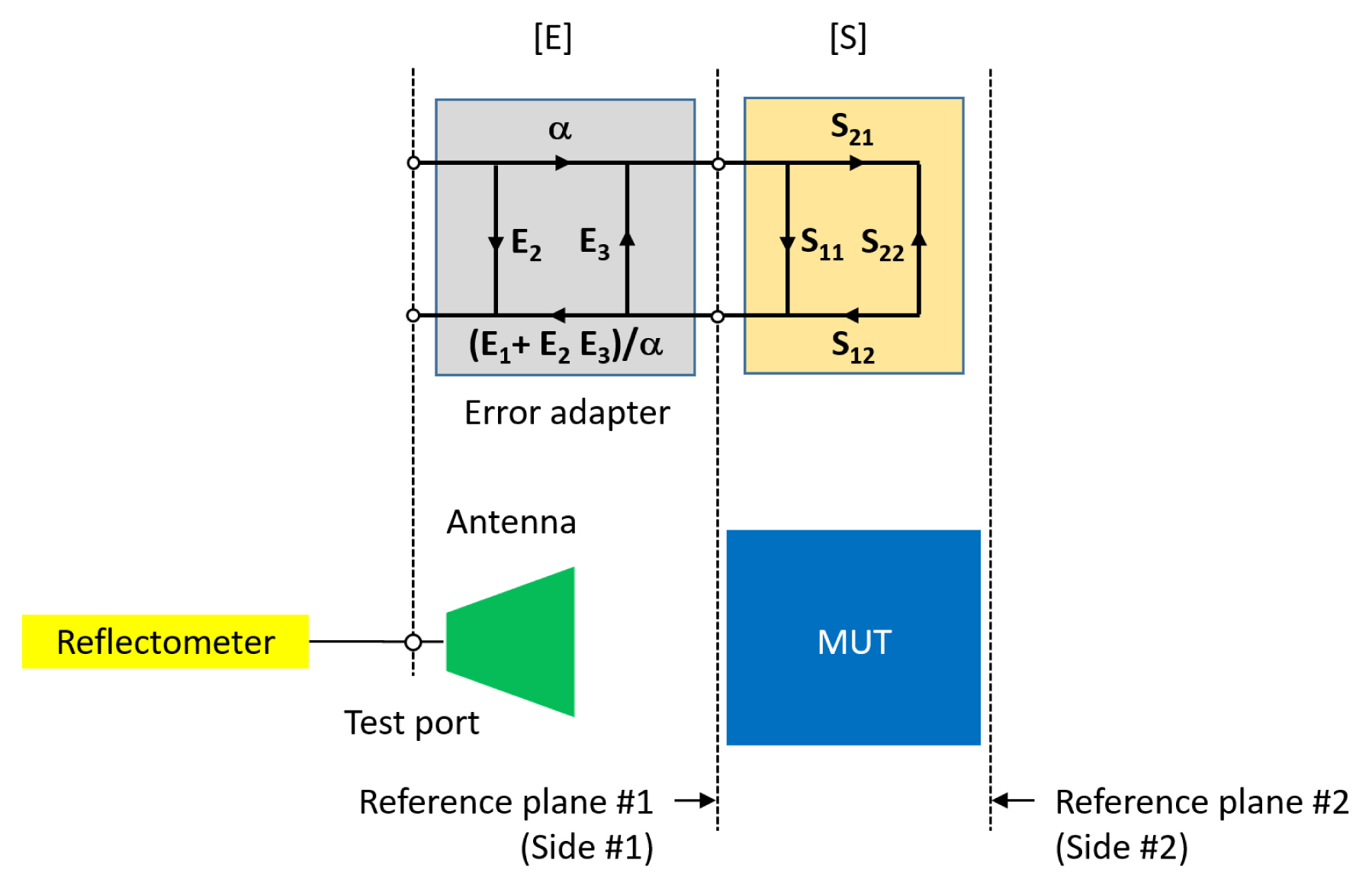
Three-term error model of a free-space one-port material measurement.
where ΓL denotes the reflection coefficient of the MUT, (E1,E2,E3) are three one-port systematic errors of the error adapter related to reflection tracking, directivity, and port match, and α denotes an arbitrary constant.
The one-port systematic errors can be determined using at least three independent reflect standards in the one-port calibration at reference plane #1. Provided that both the measured (Γm1,Γm2,Γm3) and theoretical (ΓL1,ΓL2,ΓL3) reflection coefficients of the three reflect standards are given, one may determine the systematic errors by using the following matrix equation [18]:
The systematic errors constitute the cascade matrix of the error adapter, which is given by
Once the systematic errors are determined, one can obtain the reflection coefficient of an MUT from its correction measured at the test port, which is given by
2. Free-Space Two-Tier One-Port Calibration Using Three Reflect Standards
The measurement procedure of a free-space two-tier one-port calibration using three reflect standards consists of the following steps, as shown in Fig. 3.
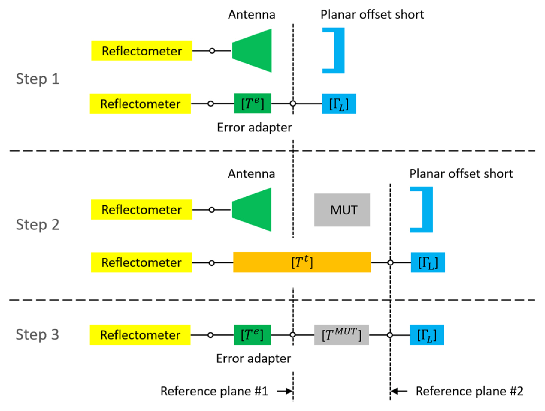
Procedure of a free-space two-tier one-port material measurement.
Step 1: One determines the cascade matrix [Te] of an error adapter from the measured (
Step 2: After placing an MUT at reference plane #1, one determines the cascade matrix [Tt] of the cascade of the error adapter and the MUT from the measured (
Step 3: One calculates the scattering matrix [SMUT] of the MUT from the cascade matrices [Te] and [Tt] obtained in Steps 1 and 2 using Eqs. (6) and (7), as shown in Step 3 in Fig. 3.
The scattering parameters of a reciprocal MUT may be explicitly expressed [22] as
The superscripts “e” and “t” denote the systematic errors obtained in Steps 1 and 2, respectively.
The free-space two-tier one-port calibration method using a planar offset short has the following advantages:
A free-space material measurement system can be easily one-port-calibrated by using a planar offset short without an expensive precision positioning system in free space.
The free-space two-tier one-port calibration can be more easily implemented than the conventional free-space two-port calibration due to the simplicity and low-cost implementation of the measurement system and operating scheme of the former.
The measured scattering parameters of an MUT are traceable to the national length standard because the property of the reflect standard used in the calibration is characterized by only the physical dimension of the planar offset short.
IV. Measurement Results
The scattering parameters of two reciprocal MUTs (glass plates of 2.780 mm and 4.775 mm thickness) are measured using a quasi-optic-based free-space material measurement system [26] calibrated by a free-space two-tier one-port method for 500 Hz IF bandwidth and 801 frequency sweep points in the W-band. The measured results are compared with those [27] of TRL calibration method.
A quasi-optic-based free-space material measurement system, as shown in Fig. 4, is composed of the following parts [26]:
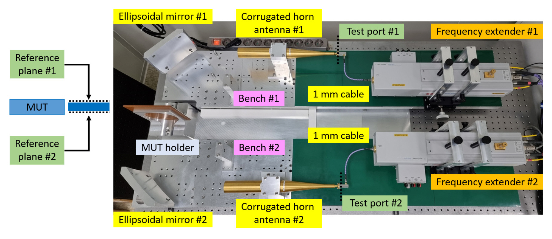
Photograph of a W-band free-space material measurement system.
A millimeter-wave scattering parameter measuring instrument consisting of a VNA as a mainframe and two frequency extenders.
A free-space quasi-optic instrument consisting of two linearly moveable benches and an MUT holder between the two benches, where each bench has a Gaussian-beamforming corrugated horn antenna and an ellipsoidal refocusing mirror on the bench and is capable of independently varying the separation distance between the bench and the MUT holder for supporting TRL calibration.
The free-space two-tier one-port and TRL calibrations are performed as follows:
The free-space two-tier one-port calibration is carried out with the two successive one-port calibrations. (i) The first one-port calibration is performed at reference plane #1, as shown in Fig. 4, by using three planar offset shorts—l = 0 mm, 0.550 mm (λ/6, 120°), 1.100 mm (2λ/6, 240°), where λ denotes the wavelength of the signal, and the angle denotes the phase difference from the phase of the reflection coefficient of the planar flush short (l = 0 mm) at the center frequency of the W-band. (ii) After placing an MUT at reference plane #1, the second one-port calibration is repeated in the same manner at reference plane #2, as shown in Fig. 4, by using the same planar offset shorts as those employed in the first one-port calibration.
The TRL calibration is carried out with measurements of (i) zero-length “Thru” by directly connecting the two reference planes, #1 and #2, of a material measurement system; (ii) “Reflect” by using a metal plate of 4.671 mm thickness inserted between the two reference planes separated by the metal plate thickness; (iii) “Line” of a quarter-wavelength delay of 0.82 mm length by separating the two reference planes by the delay, where the quarter-wavelength delay is calculated at the center frequency of the W-band. Reference plane #1 of the measurement system is stationary during the calibration.
The scattering parameters of a glass plate of 2.780 mm thickness are measured five times to compare the repeatability of the measured results obtained from the free-space two-tier one-port and TRL calibration methods. The average and standard deviation of the measured magnitude and phase data are shown in Fig. 5. Solid and empty characters of the measured data denote data obtained from the free-space two-tier one-port and TRL calibration methods, respectively. Fig. 5 shows some peaks in the measured magnitude and phase data due to external multiple reflections between the MUT and antennas and multiple reflections within the MUT inherent in a free-space material measurement.

Average and standard deviation of the magnitude and phase of the scattering parameters of a glass of 2.780 mm thickness, measured five times, obtained from free-space two-tier one-port (TO, solid character) and TRL (empty character) calibration methods without a smoothing process: (a) average and (b) standard deviation of the magnitude, and (c) average and (d) standard deviation of the phase.
Usually, one can remove the multiple reflections by taking the smoothing (i.e., moving average) and time gating of the measured results as a post-signal processing. Applying 9-point smoothing to the measured results has the following effects: (i) The multiple reflections on the magnitude and phase data are reduced, as shown in Figs. 5 and 6. (ii) The averages of the magnitude and phase obtained from the two calibration methods agree with each other, as shown in Fig. 6(a) and 6(c). These results confirm the validity of the free-space two-tier one-port calibration method using a planar offset short. (iii) For the magnitude, the standard deviation obtained from the TRL calibration method is better than that obtained from the two-tier one-port calibration method, as shown in Fig. 6(b), and vice versa for the phase, as shown in Fig. 6(d).
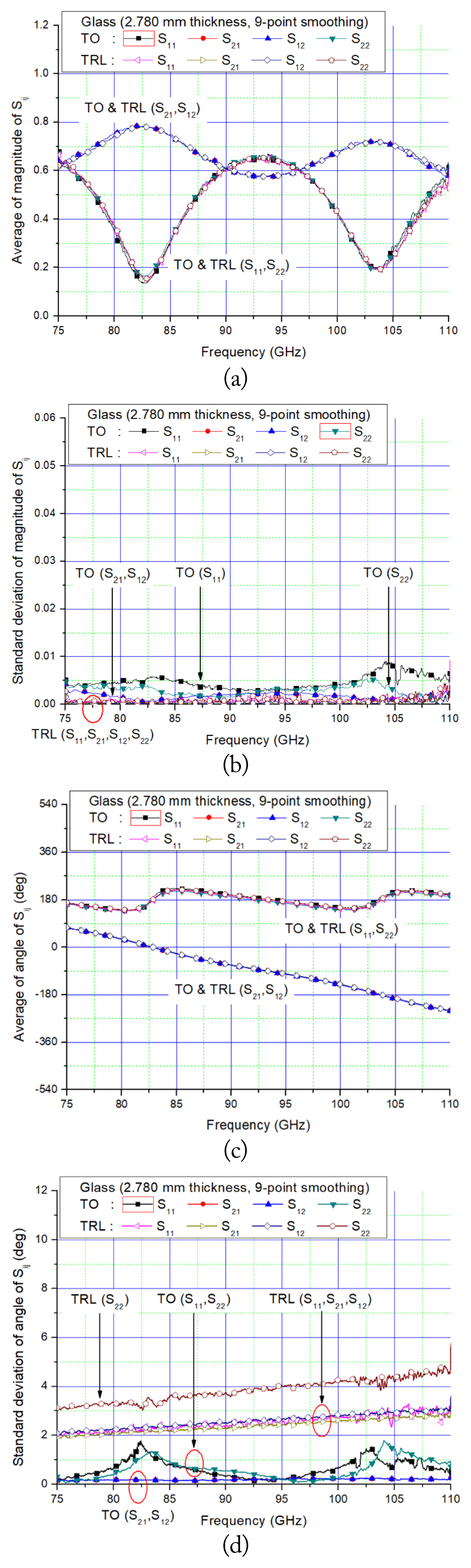
Average and standard deviation of the magnitude and phase of the scattering parameters of a glass of 2.780 mm thickness, measured five times, obtained from free-space two-tier one-port (TO, solid character) and TRL (empty character) calibration methods with a 9-point smoothing process: (a) average and (b) standard deviation of the magnitude, and (c) average and (d) standard deviation of the phase.
As the MUT becomes thicker from 2.780 mm to 4.775 mm, the measurement results show as follows: (i) The reduction of the multiple reflections on the measured magnitude and phase data is repeated, as shown in Figs. 7 and 8. (ii) The period of the magnitude of the reflection and transmission coefficients becomes shorter, as shown in Figs. 6(a) and 8(a). (iii) The magnitude of the transmission coefficients becomes smaller, as shown in Figs. 6(a) and 8(a), and the phase slope becomes steeper, as shown in Figs. 6(c) and 8(c). (iv) The standard deviation of the magnitude and phase increases with the frequency and the thickness of the MUT, as shown in Figs. 6(b), 6(d), 8(b), and 8(d).

Average and standard deviation of the magnitude and phase of the scattering parameters of a glass of 4.775 mm thickness, measured five times, obtained from free-space two-tier one-port (TO, solid character) and TRL (empty character) calibration methods without a smoothing process: (a) average and (b) standard deviation of the magnitude, and (c) average and (d) standard deviation of the phase.

Average and standard deviation of the magnitude and phase of the scattering parameters of a glass of 4.775 mm thickness, measured five times, obtained from free-space two-tier one-port (TO, solid character) and TRL (empty character) calibration methods with a 9-point smoothing process: (a) average and (b) standard deviation of the magnitude, and (c) average and (d) standard deviation of the phase.
One can enhance the standard deviation (i.e., repeatability) of the measurement results by accurately aligning the reflect standard and MUT with the propagation direction of a Gaussian beam, and accurately placing the side of the reflect standard and MUT at the reference plane of a material measurement system.
V. Conclusion
The scattering parameters of an MUT are prerequisites for characterizing the material parameters of the MUT. This paper describes a free-space two-tier one-port calibration method using a planar offset short as a free-space calculable reflect standard for measuring the scattering parameters of an MUT from two successive one-port calibrations of a free-space material measurement system without a precision positioning system in free space.
The two-tier one-port calibration method is validated by comparing the measurement results with those of the TRL calibration method for two reciprocal MUTs (glass plates of 2.780 mm and 4.775 mm thickness) in the W-band (75–110 GHz). The measurement results from the two calibration methods agree well with each other. This implies that this calibration method can be a feasible and effective alternative to the conventional free-space two-port calibration methods, such as the TRL, TRM, and GRL calibration methods, due to the simplicity and low-cost implementation of its measurement system and operating scheme.
The scattering parameters of an MUT measured from this calibration method are traceable to the national length standard because the reflection property of the planar offset short used in the calibration is determined by only its physical dimension (i.e., offset). This calibration method can be used at a high-frequency range such that the machining accuracy of the planar offset short is tolerable. The method can help characterize material parameters above a millimeter-wave frequency range.
Acknowledgments
This work was supported by the Technology Innovation Program (No. 20016225, Development and Dissemination on National Standard Reference Data) funded by the Ministry of Trade, Industry & Energy, Republic of Korea; and the Korea Research Institute of Standards and Science (No. KRISS-2021-21011008) as the project “Development of safety measurement technology for major infrastructures.”
References
Biography

Jin-Seob Kang received a B.S. degree in electronic engineering from Hanyang University, Seoul, Korea, in 1987, and M.S. and Ph.D. degrees in electrical and electronic engineering from Korea Advanced Institute of Science and Technology (KAIST), Daejeon, Korea, in 1989 and 1994, respectively. He was a postdoctoral research associate at the Department of Electrical and Computer Engineering, University of Illinois at Urbana-Champaign, in 1995, and an assistant professor at the School of Electrical and Electronic Engineering, Chungbuk National University, Korea, from 1996 to 1997. Since 1998, he has been a principal research scientist at the Korea Research Institute of Standards and Science (KRISS). He has been working on electromagnetic (EM) measurement standards, material measurements, material parameter reference standards, (sub-)mm-wave EM measurements, and non-destructive testing.