Compact 1 × 2 and 2 × 2 Dual Polarized Series-Fed Antenna Array for X-Band Airborne Synthetic Aperture Radar Applications
Article information
Abstract
In this paper, compact linear dual polarized series-fed 1 × 2 linear and 2 × 2 planar arrays antennas for airborne SAR applications are proposed. The proposed antenna design consists of a square radiating patch that is placed on top of the substrate, a quarter wave transformer and 50-Ω matched transformer. Matching between a radiating patch and the 50-Ω microstrip line is accomplished through a direct coupled-feed technique with the help of an impedance inverter (λ/4 impedance transformer) placed at both horizontal and vertical planes, in the case of the 2 × 2 planar array. The overall size for the prototype-1 and prototype-2 fabricated antennas are 1.9305 × 0.9652 × 0.05106 λ03 and 1.9305 × 1.9305 × 0.05106 λ03, respectively. The fabricated structure has been tested, and the experimental results are similar to the simulated ones. The CST MWS simulated and vector network analyzer measured reflection coefficient (S11) results were compared, and they indicate that the proposed antenna prototype-1 yields the impedance bandwidth > 140 MHz (9.56–9.72 GHz) defined by S11 < −10 dB with 1.43%, and S21 < −25 dB in the case of prototype-2 (9.58–9.74 GHz, S11 < −10 dB) > 140 MHz for all the individual ports. The surface currents and the E- and H-field distributions were studied for a better understanding of the polarization mechanism. The measured results of the proposed dual polarized antenna were in accordance with the simulated analysis and showed good performance of the S-parameters and radiation patterns (co-pol and cross-pol), gain, efficiency, front-to-back ratio, half-power beam width) at the resonant frequency. With these features and its compact size, the proposed antenna will be suitable for X-band airborne synthetic aperture radar applications.
I. Introduction
Airborne synthetic aperture radar (SAR) systems are end-to-end multimode X-band SAR systems with real-time capabilities designed for military applications like tactical surveillance and target reconnaissance. Compact and lightweight radar system designs are perfectly suited for installation on UAVs, small aircraft, helicopters, and lighter-than-air vehicles [1]. The dual polarized antenna is suitable for polarization diversity applications and to increase communication capacity. It can enhance the information content by providing two co-polarized and two cross-polarized (X-pol) back scattered data. The SIR-C shuttle imaging radar operates at L and C-bands with dual polarization at each frequency, but these two antennas do not share the common aperture. It can be used in new generation radar systems antennas can be made more compact for airborne or space-borne SAR systems for inverse SAR (ISAR) applications. Antenna technology using dual polarization is tremendously useful in communication, especially in light of the gradual increase in demand for communication channels. Such a technology should also help in reducing the cost of an antenna and its weight, as well as improving radar cross section (RCS). The efficiency of a phased array system depends on the performance of the low noise amplifier (LNA) and phase shifters, which can be achieved with the design of a high-performance phase shifter and LNA in CMOS technology presented to reduce costs [2]. Different antenna array schemes and the hand effect on the antenna array at 15 GHz were presented in [3]. An extended-resonance technique, along with a heterodyne-mixing concept, were proposed in [4]. This is capable of reducing the complexity of phased arrays by eliminating separate power dividers and phase shifters. A single-phase shifter and a separate gain controller for each antenna were presented in [5] to enable a low-cost and less complex phased array system. A new electronic beam forming in a limited scan range approach that requires only a single-phase shifter and a single gain controller, independent of the number of antenna elements, was introduced in [6]. Corporate feed and series feed networks are two possible arrangements for feeding these types of arrays, as presented by James and Hall [7]. Compared with corporate arrangements, series feed networks have the benefits of simplicity and compactness, which can translate into low-loss feeding structures as proposed by Pozar and Schaubert [8]. In the case of a corporate feeding network, numerous power dividers containing many discontinuities and long transmission lines causes spurious radiation and significant dielectric loss. Conversely, the series-fed structure (design) uses short transmission lines and enhances (improves) antenna efficiency, as presented in [9]. Improved impedance matching and radiation pattern characteristics of the series-fed arrays were presented in [10] and [11] by using a matching-in-step taper, or stepped impedance linear, configuration and adopting the method of the modified transmission line model in a 2-D array, respectively. James and Hall [7] demonstrated coupling mechanisms for series-fed arrays that include direct (microstrip line and co-axial probe feed), proximity coupled, and aperture couplings. Arrays based on direct coupling include, for example, cascaded patch arrays that were provided in [12] and comb-line antennas that were provided in [13]. In contrast to aperture coupling [14], direct coupling (microstrip line) usually requires a simpler coplanar structure rather than a multilayer design. Carter and Cashen [15] and Owens and Thraves [16] proposed series-fed arrays based on a coplanar proximity coupling mechanism. Recently, authors reported an X-band 1 × 2 linear array design with direct coupling at 9.3 GHz center frequency with a series feeding method in both xz-and yz-planes [17]. Many authors have reported X-band antenna designs [18–20] with analysis and design of a rectangular microstrip antenna in the X-band, an S-shaped patch antenna, a dielectric resonator antenna, a wideband patch antenna, and an X-band Woodpile EBG.
In this paper, a 1 × 2 series-fed linear array and a 2 × 2 series-fed planar array antenna for airborne SAR applications are presented. The antennas are designed for X-band frequency of operation. The basic antenna design consists of square patch and series feed, 50 Ω line, and quarter wave transformer etched off on top of the substrate. Matching between a radiation square patch and a 50-Ω microstrip line yields through a quarter wave transformer. The designed and simulated prototype-1 and prototype-2 were fabricated and successfully measured, and the results indicate that the proposed antenna prototype-1 (1 × 2 series-fed linear array) yields a bandwidth of 1.4% defined by S11 < −10 dB that covers 9.56–9.72 GHz. The antenna prototype-2 is a four-port series-fed planar array for dual polarization with S11 < −10 dB that covers 9.58–9.74 GHz (V1, V2 for vertical polarization, and H1, H2 for horizontal polarization) for all polarization ports. The measured result shows that the designed antenna has dual polarization capability for 2 × 2 planar arrays. The low-cost, low-profile 1 × 2 and 2 × 2 arrays have a measured gain of up to 10.91 dBi for prototype-1 and 11.04, 10.23, 10.91, and 10.71 dBi for prototype-2, with estimated radiation efficiencies around 90.71% and 85%, respectively. The simulations were performed using industry standard software CST MWS 2016 to operate in the 9.65 GHz X-band frequency range. The substrate thickness of 0.787 mm with 1 oz. copper cladding makes the prototypes flexible. The photo film of the exported DXF file was used for fabrication. The antenna was fabricated using UV exposure machine HHT-12 (a common exposure machine) according to the dimensions. The prototypes were measured using a Keysight Technologies N9918A Field-Fox microwave vector network analyzer, and the radiation patterns and gain measurements were measured in an anechoic chamber (Haining Ocean Import and Export Co. Ltd., Haining, China) of 6 m × 4 m × 3 m (L × W × H) with an Agilent PNA Series Network Analyzer N5230C (10 MHz to 40 GHz). Section II discusses the antenna requirements, Section III discusses the 1 × 2 linear array, Section IV discusses the 2 × 2 planar array, and finally, conclusions are made.
II. Antenna Structure and Design
First, the proposed 1 × 2 antenna configuration, with one excitation port as a unit cell of the arrays, is designed at 9.65 GHz. Next, the proposed cell is employed to design the 2 × 2 series-fed planar array. Prototypes of two evolution stages are presented. These 9.65 GHz 1 × 2 linear array and four-port 2 × 2 planar array consist of a microstrip line feeding or direct coupling to match the antenna impedance and series feeding for the array and four square patch elements (in the case of the 2 × 2 planar array) at the top layer and a ground plane at the bottom layer. The square array geometry with patch elements and series feed line can minimize antenna losses. In this work, an RT/duroid 5880 (Rogers Corporation, Rogers, CT, USA) copper cladding substrate, with 31 mil (0.787 mm) height, 1 oz. (i.e., 0.035 mm) thick copper, relative permittivity of ɛr = 2.2 and loss tangent of tan δ = 0.0009 was chosen as the antenna material [21]. All the metal components in the reported antenna design were taken to be copper with its known material parameters of ɛr = 1, μr = 1, and bulk conductivity of σ = 5.8 × 10⁷ s/m. The feed line and patches were patterned or etched on the top cladding layer with a laser milling machine, whereas the bottom cladding layer acts as the ground plane. After fabrication of the antenna, we used gold plating on the top and bottom of the copper layer of 1 mμ thickness for better conductivity. Later, an antenna mounting plate with a brass material of 0.8 mm thickness was fabricated and used to mount the PCB antenna using M2 (m-metric standard) stainless steel screws. A gold-plated Amphenol RF SMA male extended leg (Part No. 132134) connector was used to solder the microstrip line feed. All simulations were performed using CST Microwave Studio 2016 [22], an industry standard software simulator that is based on the finite integration technique (FIT), which is equivalent to the finite difference time domain (FDTD).
III. Proposed Antenna Design Prototype-1
1. Proposed Design of 1 × 2 Linear Array with Single Polarization
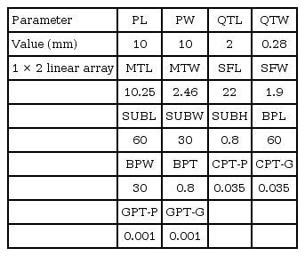
Fig. 1 shows the geometric configuration of the 1 × 2 series-fed linear array with a single RF antenna port. The S11 shows the best case of QTW = 0.28; QTL = 2 (λg = 24.57; λg/4 = 6.14) with optimization for a resonant frequency of 9.65 GHz. The value of a quarter wave transformer is 2 mm (approximately λg/10) and QTW = 0.2 mm (≈146 Ω). This impedance variation is because of the array environment. The effect of series feeding leads to an impedance change in the quarter wave transformer (λg/4). The patches are connected to each other by series feeding, using lines with dimensions of SFW and SFL that are 1.9 mm and 20 mm from the patch feed point to patch feed point toward the y-direction. To design a 0.7λ array, the value of SFL was selected to be 20 mm, which provides a scan angle of ±25° in the elevation plane from the zenith angle of the upper hemisphere, based on Eq. (1). To improve the impedance matching between the elements, the value of SFW was selected and optimized to 1.9 mm (≈59 Ω).

Geometry of the proposed antenna prototype-1 with overall dimension of 60 × 30 × 1.587 mm3. (a) Top and bottom view of CST model with dimensions, (b) fabricated prototype top and bottom view, and (c) X-band measurement setup (S-parameters with VNA and radiation pattern measurement).
The optimization was done so that the array will have the maximum gain and good matching at phi = 0 and theta = 0. The S-parameters of the optimized array are presented in Fig. 2 and show good matching around 9.56–9.7 GHz (140 MHz, 1.4%). By using the simulation software CST MWS, simulated surface current distribution, magnitude of E-fields, and a magnitude of H-fields in the microstrip line feed, as well as radiating patch for the cases with QTL, QTW, MTL, and MTW, were obtained at a resonant frequency of 9.65 GHz, as shown in Fig. 3. The designed antenna prototype-1 Smith chart and impedance parameters (Z-parameters) (real and imaginary) and phase angle of S11 were calculated using CST MWS 2016 and are shown in Fig. 4. The better impedance matching was observed in the targeted 9.65 GHz resonant frequency by achieving the real part 48.38 Ω, while the imaginary part was closer to 0 Ω as a result of better impedance matching over the operating band. The optimized dimensions of prototype-1 are given in Table 1.

Simulated surface current distribution (a), magnitude of E-field (b), and magnitude of H-field (c) in the direct coupled feed line and radiating patch of antenna prototype-1.

(a) Simulated Smith chart (48.38 Ω), (b) Z-parameters real and imaginary parts, and (c) phase angle of S11.
dy = inter-element spacing between the elements in the y-direction.
λ = free space wavelength at 9.65 GHz.
λV = free space wavelength in V-port.
θ = maximum scan angle.
2. Simulated and Measured Results
Fig. 2 shows the comparison between the simulated and measured S-parameters of the proposed single port 1 × 2 linear array antenna. For port, the simulated reflection coefficient bandwidth S11 < −10 dB achieved 9.55–9.7 GHz, while the measured bandwidth results are in the range of 9.56–9.72 GHz, or 1.4% at the center frequency of 9.65 GHz. The measured and simulated radiation patterns in terms of the E-plane and H-plane 2D polar plots are shown in Fig. 5. When exciting the RF antenna port, it is observed that the E-plane with co-pol and X-pol components has a main lobe magnitude of 11.33 dBi, side lobe level (SLL) of −25.1 dB, a front-to-back ratio (FTBR) of 30.09 dB, and an angular half-power beam width (HPBW) of 71°, respectively. In contrast, the H-plane, with its co-pol and X-pol components, has a main lobe magnitude of 10.91 dBi, a SLL of −12.9 dB, an FTBR of 30 dB, and an HPBW of 33.4°, respectively. The measured gain and efficiency of the proposed antenna is shown in Fig. 6(a). At the center frequency, the RF antenna port achieves a gain of 10.91 dBi. The simulated antenna efficiency is above 90% over the impedance bandwidth. Fig. 6(b) shows the FTBR and HPBW over frequency, which shows that there is good agreement over impedance bandwidth. Fig. 7 shows the 3D radiation patterns of the proposed antenna. When the RF antenna port is excited, the antenna achieves a gain of 11.43 dBi. The antenna performance characteristics such as SLL, FTBR, gain, 3 dB HPBW, efficiency, and X-pol levels are calculated and summarized in Table 2. The measured results mostly agree and reflect the results produced via simulations. The measured results mostly agree and reflect the results produced via simulations.

Simulated and measured E-plane (xz-plane; co-pol and X-pol) and H-plane (yz-plane; co-pol and X-pol) radiation patterns at resonant frequency 9.65 GHz. (a) V-port and (b) H-port for antenna prototype-1.
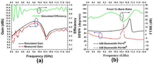
(a) Simulated and measured gain and simulated efficiency against the frequency of antenna prototype-2, (b) HPBW and FTBR over the frequency.
IV. Proposed Antenna Design Prototype-2
1. Proposed Design of 2× 2 Planar Array with Dual Polarization
Fig. 8 shows the configuration of the 2 × 2 series-fed antenna array with four ports (V1, V2, H1, and H2). The four square patches are connected to each other by series feeding in a 2D manner using the lines with dimensions of SFW and SFL, which are 1.9 mm and 20 mm, respectively, from the patch feed point to patch feed point. To design a 0.7λ array, the value of SFL was selected to be 20 mm, which provides a scan angle of ±25° in the elevation plane from zenith angle of the upper hemisphere at both the xz- and yz-planes based on the Eqs. (2) and (3) [17]. To improve the impedance matching between the elements, the value of SFW was selected and optimized to 1.9 mm (≈59 Ω). The impedance bandwidth is from 9.58 GHz to 9.74 GHz for reflection coefficient S11 < −10 dB. Also, across the impedance bandwidth, the isolation S21 is below −20 dB, with the isolation at the resonant frequency about −26 dB. By using the simulation software CST MWS, simulated surface current distribution, a magnitude of E-fields and magnitude of H-fields in the microstrip line feed along with radiating patch for the cases with QTL, QTW, MTL, and MTW were obtained at a resonant frequency of 9.65 GHz, shown in Fig. 9. The designed antenna prototype-2 Smith chart, impedance parameters (Z-parameters) (real and imaginary), and phase angle of S11 (V1-port) and S44 (H1-port) were calculated using CST MWS 2016 and are shown in Fig. 10. The better impedance matching was observed in the targeted 9.65 GHz resonant frequency by achieving the real part 48.38 Ω, while the imaginary part gets closer to 0 Ω as a result of better impedance matching over the operating band. The optimized dimensions of prototype-2 are given in Table 3.

Geometry of the proposed antenna prototype-4 with overall dimensions of 60 × 60 × 1.587 mm3. (a) Top and bottom view of CST model with dimensions, (b) fabricated prototype top and bottom view, and (c) X-band measurement setup (S-parameters with VNA and radiation pattern measurement for both V1-port and H1-port).
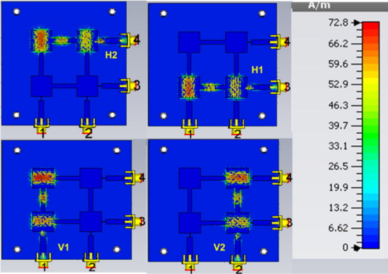
Simulated surface current in the direct coupled feed line and radiating patch of antenna prototype-2.

Simulated (a) Smith chart (S11 V1-port = 48.85 Ω and S44 H1-port = 48.85 Ω), (b) Z-parameters, real and imaginary part (S11 V1-port and S44 H1-port), and (c) phase angles of S11 V1-port and S44 H1-port.
dx = Inter-element spacing between the elements in x-direction.
dy = Inter-element spacing between the elements in the y-direction.
Θ = Maximum scan angle.
λ = Free space wavelength at 9.65 GHz.
λV = Free space wavelength in V-port.
λH = Free space wavelength in H-port.
2. Simulated and Measured Results
Fig. 11(a)–(d) shows the comparison between the simulated and measured results of S-parameters of the proposed 2 × 2 planar array antenna. For the V1-port, the simulated reflection coefficient bandwidth S11 < −10 dB achieved 9.58–9.72 GHz, while the measured bandwidth results are in the range of 9.58–9.74 GHz, or 1.4% at the center frequency of 9.65 GHz, as shown in Fig. 11(a).

Simulated and measured S-parameters for prototype-2. (a) V1-port, (b) V2-port, (c) H1-port, and (d) H2-port.
Similarly, for the V2-port, the simulated reflection coefficient bandwidth S11 < −10 dB achieved 9.56–9.7 GHz, while the measured bandwidth results are in the range of 9.56–9.71 GHz, or 1.4% at the center frequency of 9.65 GHz, as shown in Fig. 11(b). For the H1-port, the simulation predicted an impedance bandwidth from 9.56–9.7 GHz, while the measured bandwidth resulted in a range of 9.58–9.74 GHz, or 1.4% at a center frequency of 9.65 GHz, as shown in Fig. 11(c). Finally, for the H2-port, the simulation predicted an impedance bandwidth of 9.56–9.7 GHz, while the measured bandwidth resulted in a range of rom 9.58–9.74 GHz, or 1.4% at the center frequency of 9.65 GHz, as shown in Fig. 11(d). Fig. 11 shows the port isolation reaching values higher than 25 dB (S21 refers to V2–V1, S31 refers to V3–V1, and S41 refers to H1–V1). This is achieved with the selection of appropriate dimensions of quarter wave and matching transformer feeding positions.
Fig. 12 shows the measured and simulated radiation patterns produced by the proposed antenna at 9.65 GHz. When exciting the antenna’s V1-port, on the horizontal plane (xz-plane), shown in Fig. 12(a) are the measured antenna gain, HPBW, SLL, FTBR, with efficiencies of 11.04 dBi, 76.6°, −27 dB, 17.87 dB, and 86.39%, respectively. In contrast, on the vertical plane (yz-plane), the measured antenna gain, HPBW, SLL, and FTBR had efficiencies of 10.71 dBi, 32.2°, −12.3 dB, 17.87 dB, and 86.39%, respectively. For exciting of the antenna V2-port, on the horizontal plane (xz-plane), shown in Fig. 12(b) are the measured antenna gain, HPBW, SLL, FTBR, and efficiencies of 10.23 dBi, 66.4°, −25.3 dB, 17.87 dB, and 86.17%, respectively. In contrast, on the vertical plane (yz-plane), the measured antenna gain, HPBW, SLL, FTBR, and efficiency were 11.04 dBi, 76.6°, −13.3 dB, 17.87 dB, and 86.17 %, respectively. For exciting of the antenna H1-port, on the horizontal plane (yz-plane), shown in Fig. 12(c) are the measured antenna gain, HPBW, SLL, FTBR, and efficiencies of 10.91 dBi, 35.7°, −13.3 dB, 17.87 dB, and 90%, respectively. In contrast, on the vertical plane (xz-plane), the measured antenna gain, HPBW, SLL, FTBR, and efficiencies were 10.23 dBi, 66.4°, −25.3 dB, 17.87 dB, and 86.17%, respectively. For exciting of the antenna H2-port, on the horizontal plane (yz-plane), shown in Fig. 12(d) are the measured antenna gain, HPBW, SLL, FTBR, and efficiencies of 10.71 dBi, 32.2°, −27 dB, 17.87 dB, and 86.39%, respectively.

Simulated and measured E-plane (xz-plane; co-pol and X-pol) and H-plane (yz-plane; co-pol and X-pol) radiation patterns at resonant frequency 9.65 GHz. (a) V1-port, (b) V2-port, (c) H1-port, and (d) H2-port for antenna prototype-2.
In contrast, on the vertical plane (xz-plane), the measured antenna gain, HPBW, SLL, FTBR, and efficiencies were 11.04 dBi, 76.6°, −27 dB, 17.87 dB, and 86.39%, respectively. When the RF antenna port is excited, the antenna achieves a gain of 11.43 dBi. The measured gain of the proposed antenna for both the ports are shown in Fig. 13(a). At the center frequency, both the vertical port and the horizontal port achieve a gain of 11 dBi. The FTBR over the X-band is presented in Fig. 13(b). The FTBR values are from 25–32 dB at the X-band (9.65 GHz). The 3-dB HPBWs over the X-band are depicted in Fig. 13(b). Fig. 14 shows the 3D radiation patterns of the proposed antenna. The antenna performance characteristics, such as SLL, FTBR, gain, 3-dB HPBW, efficiency, and X-pol levels are calculated and summarized in Table 4. The measured results mostly agree and reflect the results produced via simulations.

(a) Simulated and measured gain and simulated efficiency against the frequency of antenna prototype-2 and (b) HPBW and FTBR over the frequency.
3. Proposed Design of 2× 2 Planar Array with 2-Way Power Divider with Enhanced Gain
Fig. 15 shows a photograph of the fabricated prototype. Fig. 16 shows a comparison of the simulated and measured results of S-parameters for the proposed 2 × 2 planar array antenna integrated with a 2-way power divider. For the V-port, the reflection coefficient bandwidth S11 < −10 dB achieved 9.5–9.7 GHz, or 1.5%. Similarly, for the H-port, the reflection coefficient bandwidth S11 < −10 dB achieved 9.56–9.7 GHz bandwidth.
Fig. 17 shows the measured and simulated radiation patterns produced by the proposed antenna at 9.65 GHz. For exciting of the antenna V-port, on the horizontal plane (xz-plane), Fig. 17(a) shows the measured antenna gain, HPBW, SLL, FTBR, and efficiencies of 15.2 dBi, 35, −23 dB, 25 dB, and 86.39%, respectively. In contrast, on the vertical plane (yz-plane), the measured antenna gain, HPBW, SLL, FTBR, and efficiencies were 10.71 dBi, 32.2°, −12.3 dB, 17.87 dB, and 86.39%, respectively.
For exciting of the antenna H-port, on the horizontal plane (yz-plane), shown in Fig. 17(b) are the measured antenna gain, HPBW, SLL, FTBR, and efficiencies of 15 dBi, 35.7°, −18 dB, 22 dB, and 90%, respectively. In contrast, on the vertical plane (xz-plane), the measured antenna gain, HPBW, SLL, FTBR, and efficiencies of 10.23 dBi, 36°, −25.3 dB, 17.87 dB, and 86.17%, respectively.
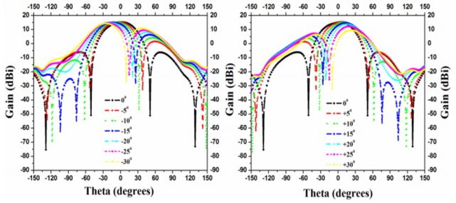
The beam scanning is achieved by applying the different excitation phase values to the 2-input ports for vertical polarization. To study the beam scanning capability of the 2 × 2 array antenna, and because of the symmetry, first, all the ports are excited with zero degree phase and equal amplitude, which results in a maximum gain equal to 15.3 dBi in the broadside direction (θ = 0°). Here, the SLL is −25 dB at both the XZ-plane and the YZ-plane. Next, the phases of the vertical ports are adjusted to 22.5° and 45°, (tilt angle θ = 5°), 45° and 90° (tilt angle θ = 10°), 67.5° and 135° (tilt angle θ = 15°), 90° and 180° (tilt angle θ = 20°), and 112.5° and 202.5° (tilt angle θ = 25°), respectively, shown in Fig. 18. As an example, the plot (xz-plane) shown represents the gain maximization output at all of the respective tilting angles. A gain variation of less than 1.2 dBi (14–15.2 dBi) was observed over the tilt angle ±25°. The spacing between the elements that was chosen was 0.7λ to reduce the grating lobes free scanning up to 25°. Increasing the tilt angle beyond the selected scan angle leads to performance degradation, which was found to be 30°.
4. Proposed Design of 2× 2 Planar Array with Hybrid Coupler for Circular Polarization
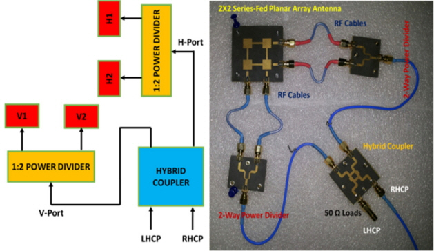
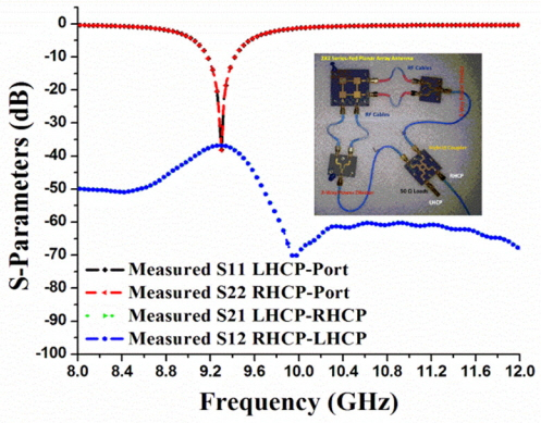
An antenna prototype of the proposed 2 × 2 planar array integrated with a hybrid coupler for circular polarization characteristics was fabricated and experimentally characterized to validate the design, as shown in Fig. 19. As illustrated in Fig. 20, the measured S-parameters for the antenna were shown to be in good agreement. The antenna operational bandwidth is defined as the band where the measured reflection coefficients (S11, S22) are −10 dB and the isolation S21–S12 are −20 dB below. For the left-hand circular polarization (LHCP) port, the reflection coefficient bandwidth S11 < −10 dB achieved 9.5–9.7 GHz, or 1.5%. Similarly, for the right-hand circular polarization (RHCP) port, the reflection coefficient bandwidth S11 < −10 dB achieved 9.56–9.7 GHz bandwidth. The simulated and measured LHCP and RHCP radiation patterns in the xz- and yz-planes at 9.65 GHz are shown in Fig. 21. Each of the LHCP and RHCP arrays are accomplished with a gain up to 15.2 dBi. Table 5 shows the comparison with previous work at the X-band.
V. Conclusion
Dual polarized series-fed 1 × 2 linear and 2 × 2 planar array antennas for airborne SAR applications have been presented. By using the series-fed network, there are fewer losses associated with feed line. The 2 × 2 planar array antenna can be employed as a dual polarized antenna to selectively generate vertical and horizontal polarized waves. Its radiation characteristics can be improved by using a series-fed structure as a feeding network. The overall size of the antennas, prototype-1 and prototype-2, have dimensions of 60 × 30 × 1.587 mm3, (1.9305 × 0.9652 ×0.05106 λ03) and 60 × 60 × 1.587 mm3 (1.9305 × 1.9305 ×05106 λ03), respectively, which operate at a 9.65-GHz center frequency (λ0 is free space wavelength). A detailed comparison of the performances of the proposed 1 × 2 linear array and 2 × 2 planar array were also presented with integration of a 2-way power divider (for gain enhancement) and hybrid coupler (for circular polarization). Additionally, beam scanning mechanism also implemented for tilting angle of ±30°. The antenna prototypes were fabricated and experimentally characterized. The good agreement between the simulations and the experimental results validated the designs. In addition, the antenna provides stable radiation patterns, 3-dB beam width, SLL, and good FTBR for SAR applications. Moreover, the proposed prototype antennas also feature simple and compact structures.
References
Biography
Venkata Kishore Kothapudi (S’14–M’18) was born in Tenali, India, in 1987. He received a degree in electronics and communication engineering from TPIST, JNTU, Hyderabad, India, in 2008 and a M.Tech. degree in communication and radar systems from the Koneru Lakshmaiah Education Foundation, India, in 2012. He is currently pursuing a Ph.D. degree with the Microwave Division, School of Electronics Engineering (SENSE), Vellore Institute of Technology (VIT), Vellore, India. He has over seven years of research and industry experience in RF and microwave engineering, in ECIL as a GEA, NARL-ISRO as a project student, and Astra Microwave Products as an engineer. He has rich experience in radar systems design, which includes transmit/receive modules (HF-, VHF-, L-, S-, and C-band), RF and microwave feeder network and beam forming, RF and microwave active and passive components, RF power amplifiers, and antenna systems, including the Yagi-Uda and the microstrip patch antennas as a phased array with different configurations by using analysis and synthesis techniques. He has published over 15 research papers in IEEE Access, with a 3.244 impact factor; the Progress in Electromagnetic Research (PIER) international journal, and IEEE international conferences. He travelled to Sri Lanka and Singapore for the IEEE SYWC 2015 meeting and the IEEE APSAR 2015 conference, respectively, to present his research work and as a part of his research. He has authored and co-authored many IEEE proceedings papers. His areas of research interest include shared aperture antenna technology for radar engineering, airborne and space-borne synthetic aperture radar, and radar wind profilers. He is a member of IEEE (AP-s., MTT-s., AES-s.,GRS-s., IP-s., ComSoc & EMC-s.), AIAA, and ACES.

Vijay Kumar (S’08–M’12) received a M.Sc. degree in physics (electronics) from the Magadh University, India, in 2003. He has completed an M.Tech. degree in microwave remote sensing from BIT Mesra, Ranchi, in 2005, and completed his Ph.D. in engineering at IIT Bombay, Mumbai, in 2011. He worked as a DST government of India sponsored scientist at IIT Bombay from 2009 to 2012. Presently, Kumar is working as an associate professor at VIT University, Vellore TN, India. He is author and contributing author of many peer-reviewed journal papers and more than twenty proceedings papers. Kumar’s research interests are in radiating system designs for radar applications and miniaturized antenna designing using metamaterials. He has also been concentrating on SAR processing algorithm development, InSAR techniques, and SAR image processing and pattern recognition. He is a life member of ISRS and a member of AGU, SPIE, and IEEE.


