Emulator for Generating Heterogeneous Interference Signals in the Korean RFID/USN Frequency Band
Article information
Abstract
In this study, we suggest an emulator for generating multiple heterogeneous interference signals in the Korean radio frequency identification/ ubiquitous sensor network (RFID/USN) frequency band. The proposed emulator uses only one universal software radio peripheral to generate multiple heterogeneous interference signals more economically. Moreover, the physical and media access control parameters can be adjusted in real time using the LabVIEW program, thereby making it possible to create various time-varying interference environments easily. As an example showing the capability of the proposed emulator, multiple interference signals consisting of a frequency-hopping RFID signal and two LoRa signals with different spreading factors were generated. The generated signals were confirmed in both frequency and time domains. From the experimental results, we verified that our emulator could successfully generate multiple heterogeneous interference signals with different frequency and time domain characteristics.
I. Introduction
Recently, various wireless communication devices and services that use an unlicensed frequency band, including smartphones, tablets, and Internet of Things (IoT) devices, among others, have been deployed exponentially. However, because the frequency resources of the unlicensed band are limited, wireless devices operating in it may experience various interferences with each other [1, 2].
As frequency interference between wireless devices suppresses the smooth provision of these services, examining how to allocate frequency channels to each service and to manage their coexistence efficiently is necessary. Specifically, quantitative studies on the influence of frequency interference between different wireless devices should be conducted [3].
The analysis method of frequency interference is categorized into two types, namely, software and hardware method, depending on whether real hardware devices exist or not. Various hardware methods for analyzing frequency interference problems are reported in [4–6]. In [4], real wireless hardware is used to emulate the interference environment. However, when real hardware device is used, changing the physical (PHY) and media access control (MAC) layer parameters is difficult because they are generally embedded inside the modem chip. A signal generator also can be used to emulate interfering signals [5]. Although a signal generator is highly controllable, it is expensive and makes adjusting the various physical and MAC layer parameters difficult. Therefore, we propose a method to develop a versatile frequency interference emulator using a software-defined radio (SDR) and the LabVIEW program in [6]. It can effectively adjust various space, frequency, and time domain parameters. However, because [6] uses an identical physical and MAC scheme, this emulator can implement only a single homogeneous wireless network. Therefore, developing an emulator to simulate heterogeneous interference environments remains challenging. Fortunately, Liu et al. [3] proposed a new method to emulate heterogeneous interference signals using the orthogonal frequency division multiplexing (OFDM) scheme. However, the authors only showed the emulation results of Bluetooth interference signals using a complex field programmable gate array (FPGA)-based test-bed. Moreover, implementing a MAC protocol is easy because Bluetooth uses a relatively simple frequency-hopping multiple-access scheme without carrier sensing. Various studies are still needed to make a versatile heterogeneous frequency emulator both in various frequency bands and MAC protocols. Specifically, an emulator than can easily use a commercial universal software radio peripheral (USRP) as the SDR equipment is needed.
In this study, we propose an emulator for generating multiple heterogeneous interference signals in the Korean radio frequency identification/ubiquitous sensor network (RFID/USN) frequency band (917–923.5 MHz). In this frequency band, various wireless devices, such as wireless LAN (WLAN), wireless PAN (WPAN), Z-wave, RFID, and LoRa, coexist. Therefore, reducing hardware complexity by the use of a single radio is necessary. Our emulator can effectively combine the OFDM scheme in [3] and our method in [6]; therefore, multiple heterogeneous networks can be emulated using only a single SDR board. As an example of performance verification of the proposed emulator, we generated heterogeneous interference signals consisting of a frequency-hopping RFID signal and two LoRa networks with different spreading factors in different frequency channels. To show the applicability and versatility of the proposed emulator, we used a commercial USRP as the SDR equipment provided by National Instrument and the LabVIEW program as the USRP-driving software.
II. Heterogeneous Interference Scenario
1. Korean RFID/USN Frequency Band
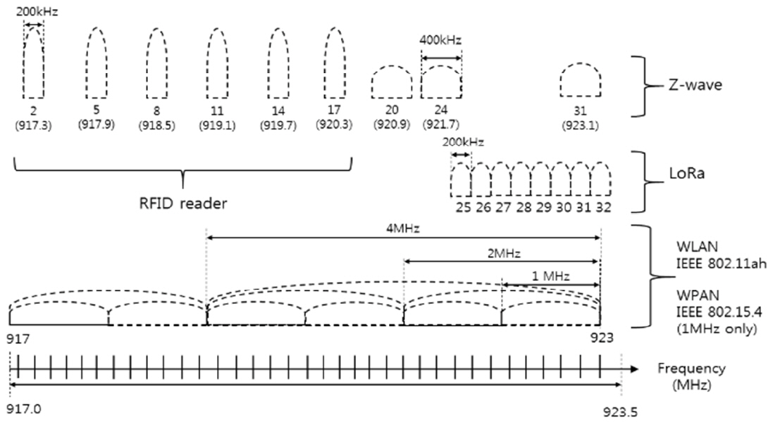
Today, various wireless devices can be found in the Korean RFID/USN frequency band. First, ultra-high frequency (UHF) passive RFID can be found. The RFID system consists of a reader and a tag. A reader sends the carrier to a tag. The reader then receives a backscattered signal from the tag, which is powered by a continuous wave from the reader. Unlike in other wireless communication systems, interference occurs when a reader transmits a command signal that interferes with the tag reception procedure of another reader. To prevent RFID interference to another wireless device, the six frequency channels of #2 (917.3 MHz), #5 (917.9 MHz), #8 (918.5 MHz), #12 (919.1 MHz), #14 (919.7 MHz), and #16 (920.3 MHz) are allocated for the dense RFID mode with a 600 kHz interval [7].
Second, LoRa network signals are available. LoRa is the proprietary standard for IoT. It uses six spreading factors (SF7 to SF12) to adapt the data rate and coverage tradeoff. A higher spreading factor enables a longer coverage at the expense of a lower data rate, and vice versa. The LoRa data rate is between 300 bps and 50 kbps depending on the spreading factor and the channel bandwidth. Korea has eight LoRa channels, from #25 (921.9 MHz) to #32 (923.3 MHz), with a 200 kHz interval [8].
Third, the Z-wave using the ITU-T Recommendation G.9959 Standard can be deployed for home network systems, such as heating, ventilation, air conditioning, lighting, and security systems. The Korean RFID/USN frequency band has three Z-wave channels, namely, #20 (920.9 MHz), #24 (921.7 MHz), and #31 (923.1 MHz), with a 400 kHz frequency bandwidth.
Finally, there are emerging WLAN (Wi-Fi) and WPAN (ZigBee) standards operating on the sub-GHz frequency band. For example, the IEEE 802.11ah WLAN signal uses up to a 4 MHz bandwidth, and the IEEE 802.15.4 WPAN signal uses a 1 MHz bandwidth. As these WLAN and WPAN signals have wideband characteristics, LoRa can be a victim. The detailed channel allocations in the Korean RFID/USN frequency band are shown in Fig. 1.
2. Interference Scenario
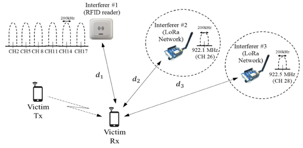
As multiple wireless devices with different standards exist in the Koran RFID/USN frequency band, various interference phenomena can occur. For example, a high-power RFID device may interfere with a sub-GHz Wi-Fi device. A LoRa device can also interfere with a Wi-Fi signal at the same time. As a worst case, a sub-GHz Wi-Fi device with a 4 MHz bandwidth may be affected by RFID, LoRa, and Z-wave simultaneously, as shown in Figs. 1 and 2.
Generally, an interference environment consists of interferers, a victim, and a channel. In a victim receiver, multiple interference signals on the channel are received with the victim’s transmitted signal. In the frequency aspect, interference between wireless devices occurs when the transmitter uses an identical frequency channel of the interferer. Moreover, interference occurs when the transmitter and interference signals transmit signal at the same time and exist in a nearby space where they can affect each other. Therefore, when modeling interference environments, adjusting the parameters freely in the frequency, time, and space domains, respectively, is necessary.
III. Configuration of the Proposed Emulator
The Korean RFID/USN band has multiple heterogeneous interferers. Generally, a high-frequency signal may be generated with a signal generator. Therefore, as shown in Fig. 3(a), n signal sources are needed, with one signal source per interferer, to generate n interferers. However, as the number of interferer increases, the system becomes more complex. Fortunately, developing a homogeneous multi-interference environment using an SDR device with a MAC signal generating capability is possible [6]. In [6], multiple nodes comprising a homogeneous network can share the time channel using an appropriate MAC protocol.
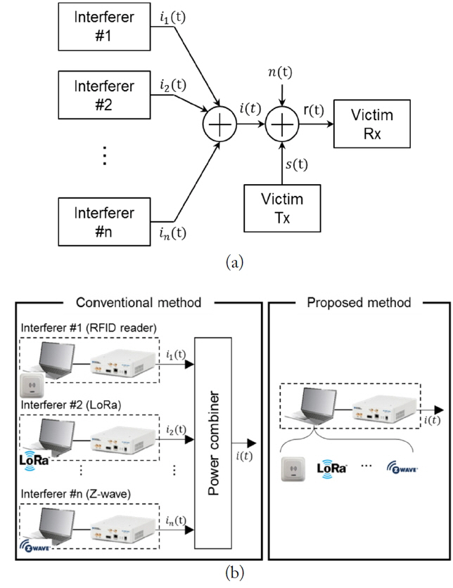
Emulation for the interference environment: (a) the interference signal generator using multiple signal generators and (b) the interference signal emulator using only one signal generator with a heterogeneous signal generation function.
However, using the method of [6] is difficult because multiple heterogeneous interferers have separate MAC protocols. In the current paper, we adapt the method of Liu et al. [3] using the OFDM modulation scheme. Owing to the OFDM technology having multiple subcarriers, the proposed emulator can emulate various narrowband signals in the Korean RFID/USN bands. As shown in Fig. 3(b), it is an economical and realistic approach.
1. Physical Layer Modeling
As shown in Fig. 4, the physical layer of the proposed emulator uses the OFDM modulator scheme.
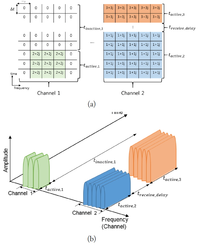
Concept of the heterogeneous interference emulator: (a) the matrix form and (b) the signal generation for the matrix form.
Interference signals are realized by a finite length of OFDM symbol and subcarrier. First, the total bandwidth of the Korean RFID/USN frequency band is divided into each sub-carriers similar to the OFDM scheme.
If a 1024-point iFFT is used, it will offer 170.7 μs Δt long and 5.8 kHz wide Δf, which are considerably smaller than the packet length and resolution bandwidth, respectively, of the RFID and LoRa waveforms. Second, multiple subcarriers can be combined to construct the operating channel bandwidth of the specific node. For example, if the operating bandwidth of node #1 is the same as the bandwidth of the three successive subcarriers, three subcarriers will be allocated to node #1. Similarly, five subcarriers are allocated to node 2 with a narrow channel bandwidth. As shown in Fig. 4(a), if the channel bandwidth of a specific signal is an integer multiple of the subcarrier, that signal can be generated by adjusting the number of subcarriers. In addition, the signal duration time can be adjusted by the multiple numbers of OFDM symbols. Finally, the received signal power can be specified by modifying the magnitude of the subcarriers given by a complex number expressed by n + jn. Therefore, the magnitude of a signal can be adjusted by controlling the n value as shown in Fig. 4(a). The actual values of n are calculated by considering the transmitting power of the interferer and path loss to a victim receiver. All of these parameters in the PHY layer are controlled through the LabVIEW program and the USRP. Fig. 4(b) shows the signal waveform designed by Fig. 4(a) in the time, frequency, and amplitude domains.
2. MAC Layer Modeling
In a wireless network, nodes send and/or receive data in a manner specified by its MAC protocol. In addition, the MAC protocols define the retransmission methods to prevent data loss that may occur during transmission.
Generally, the transmitter retransmits its previously transmitted data if it does not receive an ACK signal from the receiver within a certain time.
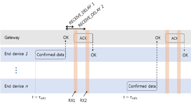
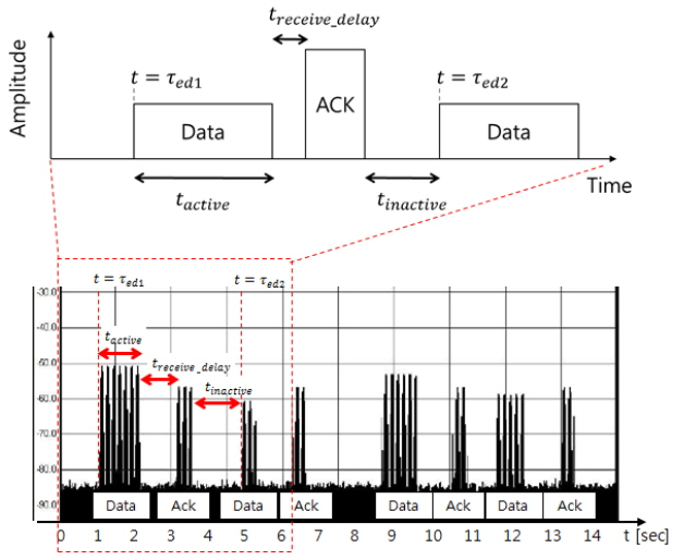
For example, let us consider the uplink timing diagram of the LoRa network in Fig. 5. A LoRa network consists of one gateway and n end devices (EDs). As the LoRa standard adopts ALOHA as a wireless access scheme, the start time of the uplink transmission of the nth ED, τedn, is a random value. LoRa also uses the RX1 or the RX2 time slot for downlink transmission [9, 10].
The RX1 opens RECEIVE_DELAY1 seconds after the end of the uplink modulation, and the RX2 opens RECEIVE_ DELAY2 seconds. Whereas the RX1 uses the same frequency channel as the uplink and the data rate is a function of the data rate used for the uplink, the RX2 uses a fixed configurable frequency and a data rate.
Similar to LoRa networks, RFID readers and tags also use ACK messages for their reliable data transmission.
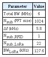
The configuration of the proposed emulator is shown in Fig. 6. The emulator consists of a personal computer (PC) for running LabVIEW and a USRP-2922 SDR device device for signal generation. Various interference signals were created by adjusting the parameter values set in the LabVIEW program (Table 1). The signals were sent to the USRP over the Gbps Ethernet cable and emitted to that frequency band. The radiated interference signal was confirmed by a spectrum analyzer.
IV. Implementation Results
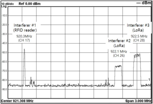
To verify the capability of the proposed emulator, we constructed an actual heterogeneous interference environment. We again used the previous example in Fig. 2. As shown in Fig. 2, the RFID reader (interferer #1) was set to hop on the frequency channels 2, 5, 8, 11, 14, and 17 every 0.4 seconds, and two LoRa devices (interferer #2 and interferer #3) were established with different data rates on channels 26 (922.5 MHz) and 28 (922.1 MHz). Each of the three interference sources had different operating channels, operating modes, and driving times, respectively.
Table 2 presents the parameter settings for interference power according to distance for the scenario in Fig. 2. Pint.Tx,n is the power of the interference signal generated by the nth interferer, and Pint.Rx,n is the interference power received by the victim RX via path dn. After selecting the interferers and the interference power, setting the parameters for the PHY and MAC layers of the interferers is necessary. The PHY and MAC layer parameters for each interferer were set through the LabVIEW program on a PC. The interference signal was up-converted to the RFID/USN band through the USRP-2922 [11, 12].
Fig. 7 shows the power spectral density (PSD) of a heterogeneous multi-interfering signal transmitted through the USRP-2922. We measured the PSD using a N9010A spectrum analyzer from Agilent Technologies.
Furthermore, the PSD was obtained using the max-hold function on the instrument. The results of the PSD measurements confirmed that three interfering signals occurred on the specified channel. The RFID reader generated a narrow band signal on channel 17. The RFID reader hopped six channels and displaced only one channel because of the max-hold function of the instrument. The LoRa devices generated signals with a bandwidth of 125 kHz on both channels 26 and 28, which use the modulation schemes of chirp spreading spectrum as the LoRa standard.
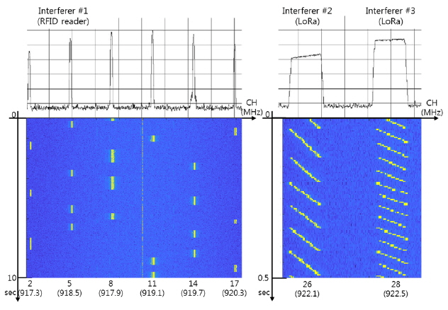
To generate chirp signals using the OFDM, the first step is to select two successive subcarriers for generating a narrowband signal. Then, by sequentially increasing the position of the subcarriers, an up-chirp signal can be generated. Similarly, sequentially decreasing their position can generate a down-chirp signal. In addition, by adjusting the increasing position of the subcarrier, chirp signals of various intervals can be generated (Fig. 8).
Fig. 8 also illustrates the spectrogram of the interference signals on each channel. The RFID reader hops on a six-frequency channel every 0.4 seconds. The LoRa signals modulated by the chirp spreading spectrum are generated as different spreading factors on channels 26 and 28, respectively. The upper part of Fig. 8 shows the various interference signals in the frequency domain by the max-hold function of the spectrum analyzer. The lower part of the spectrogram presents the generated signals in the time-frequency domain. This spectrogram was generated by post-processing the received signal using the MATLAB.
Fig. 9 shows the timing diagram example of the LoRa data and ACK data. This timing diagram is a LoRa network signal generated on channel 28, and it was obtained using the zero span function of the signal analyzer. In Fig. 9, treceive_delay depends on the length of the LoRa packet and data. The active time duration, tactive, has various values, such as tactive,1, tactive,2, and tactive,3, given in Fig. 4(a). The inactive time duration, tinactive, is usually a random value caused by the random access schemes of RFID and LoRa, slotted ALOHA, and ALOHA, respectively.
V. Conclusion
We suggested an emulator for generating heterogeneous multi-interference signals to conduct various frequency interference experiments. The proposed emulator uses only one USRP to generate multiple heterogeneous interference signals economically. Moreover, the physical and MAC parameters can be adjusted in real time using the LabVIEW program, thereby making it possible to create various time-varying interference environments easily.
References
Biography
Sangjoon Lee received his B.S. degree in electrical engineering from Kookmin University, Seoul, Korea, in 2017. He is currently working toward his M.S. degree in the Department of Electrical Engineering, Kookmin University. His current research interests are in the areas of local positioning, radar signal processing, frequency interference modeling and spectrum engineering, and software-defined radio.

Kyung-Jin Baik received her B.S. degree in electrical engineering from Kookmin University, Seoul, Korea, in 2017. She is currently working toward her M.S. degree in the Department of Electrical Engineering, Kookmin University. Her current research interests are in the areas of local positioning, radar signal processing, motion recognition, and machine learning.

Hyungoo Yoon received his B.S., M.S., and Ph.D. degrees in electronics engineering from Yonsei University, Seoul, Korea, in 1995, 1997, and 2002, respectively. From 2002 to 2004, he worked at Hyundai Electronics in Incheon, where he developed code-division multiple access base stations. Since 2004, he has been a professor at the Department of Electronic Engineering at Myongji College, Seoul, Korea. His main research interests include radio resource management, interference mitigation techniques, multiple-input multiple-output systems, and spectrum engineering.

Byung-Jun Jang received his B.S., M.S., and Ph.D. degrees in electronic engineering from Yonsei University, Seoul, Korea, in 1990, 1992, and 1997, respectively. From 1995 to 1999, he worked for LG Electronics in Seoul, where he developed code-division multiple access and digitally enhanced cordless telecommunication RF modules. From 1999 to 2005, he was with the Electronics and Telecommunications Research Institute, Daejeon, Korea, where he performed research in the fields of satellite RF components and monolithic microwave integrated circuits. In 2005, he joined Kookmin University, Seoul, where he is currently with the Department of Electrical Engineering. His current research interests are in the areas of RF circuit design, radio frequency identification system design, wireless power transfer system design, frequency interference modeling and spectrum engineering, and wireless sensor design.

