Metaheuristic Optimization Techniques for an Electromagnetic Multilayer Radome Design
Article information
Abstract
In this study, an effective method for designing an electromagnetic multilayer radome is introduced. This method is achieved by using ant colony optimization for a continuous domain in the transmission coefficient maximization with stability for a wide angle of incidence in both perpendicular and parallel polarizations in specific X- and Ku-bands. To obtain the optimized parameter for a C-sandwich radome, particle swarm optimization algorithm is operated to give a clear comparison on the effectiveness of ant colony optimization for a continuous domain. The qualification of an optimized multilayer radome is also compared with an effective solid radome type in transmitted power stability and presented in this research.
I. Introduction
The problem of an electromagnetic multilayer dielectric design optimization for a frequency band and a desired range of incident angles has been introduced in recent years using such metaheuristic optimization algorithms as the genetic algorithm [1, 2], particle swarm optimization (PSO) [3, 4], or a hybrid algorithm that combines ant colony optimization (ACO) with the microgenetic algorithm [5]. In this study, an effective algorithm presented by Socha and Dorigo [6] in 2008 called ant colony optimization for a continuous domain (ACOR) is applied to design a C-sandwich radome [7] with an applicable range of incident angle (0°–70°) in both the transverse electric (TE) and transverse magnetic (TM) modes for the X- and Ku-bands. To validate the ACOR algorithm in a multilayer radome design optimization, the performance of the transmission coefficient characteristics of the C-sandwich radome design optimized by ACOR has been compared with a conventional analysis method (i.e., a simpler and lower-cost analysis) that approximates multilayer radomes by a solid radome with an effective medium approximation (EMA) [8, 9]. Then, the performance of ACOR is compared with a general optimization algorithm used in electromagnetic characteristic design (i.e., PSO). This study is organized as follows: Section II is an overview of the ACOR algorithm, which uses a boundary value method to evaluate the transmission coefficient of a multilayer radome. Section III examines the fitness function and compares the optimization results obtained by ACOR and PSO. The simulation results and the transmitted power stability are compared with an effective solid radome, and the results are discussed. The conclusion is provided in Section IV.
II. Methods
1. Ant Colony Optimization for a Continuous Domain
Originally, ACO was introduced in 1992 by Dorigo [10], and it has been used to solve many combinational optimization problems consisting of a set of discrete decision variables. The idea of applying ACO in solving the continuous optimization problem was presented in 2008 by Socha and Dorigo [6]. The flowchart of the ACOR algorithm is illustrated in Fig. 1.

Flowchart of ACOR algorithm.
In ACOR, the solutions are kept and sorted in a solution archive (Fig. 2), in which the associated weight of solution l defined in Eq. (1) represents the strength of the solution in producing new solutions.
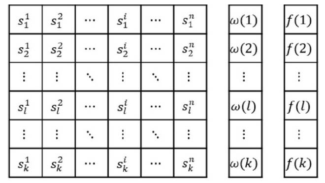
Solution archive of the ACOR algorithm with
To generate new solutions, a kernel is selected by probability that is computed for each group as in Eq. (2).
Roulette wheel selection [11] is applied to select a solution kernel. Each probability p(l) is presented as a proportion of the wheel (Fig. 3), and a random selection process is made similarly to rotate the roulette wheel. An m new random number group according to the parameterized normal distribution is used with mean (
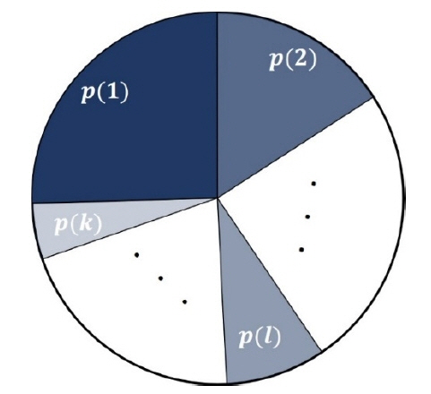
Roulette wheel with a probability of solution p(l) as the proportion of the wheel.
ξ>0 is a constant parameter that is similar to the pheromone evaporation rate in ACO [10]. Then, m new solutions are added to the solution archive and re-ordered. Non-fit solutions are removed, and only the k best ones are kept after each iteration.
2. Transmission Coefficient Characteristic of the C-Sandwich Radome
A C-sandwich radome, which is a multilayer radome (style d) [7], is considered in this work. The sandwich wall has five layers that were developed to cover an antenna array operating in a wide-band frequency range. The C-sandwich construction consists of three skins that are interleaved by two cores. Typically, the relative permittivity of skin is greater than that of the core. To guarantee that the input and output of the propagation wave are equal, a C-sandwich wall is designed with the first and last skins having the same thickness, and the widths of the two cores are the same as well. To fabricate a radome, the thickness of each layer is designed as the multiple of plies. The propagation wave on the radome with layer i has thickness di, relative permittivity ɛi, loss tangent tanδi, and refractive index ni. The Fj (j ∈[1,7])/Bk(k∈[1,6]) are the forward and backward propagation waves, respectively. The forward and backward fields at the first left interface are related to Eq. (5).
τi =1+ri and ri is the intrinsic reflection coefficient of each interface and is calculated by the Fresnel equation. If one uses the formula in Eq. (5) and simplifies it to Eq. (6), the transmission coefficient can be obtained by Eq. (7).
III. Results and Discussion
1. Fitness Function
The main objective of this research is to maximize the transmission coefficient of a multilayer structure radome, which is calculated by Eq. (7) in a specific frequency band with various angles of incidence in both the TE and TM modes. To ensure the stability of the transmission coefficient, the following objective function is considered for optimization:
where T(f,θ) is the transmission coefficient at frequency f and incident angle θ.
2. Optimization Design Result
The optimized thickness design is compared with an effective solid radome type with a half-wavelength thickness. The transmitted power is 80% greater in both polarizations, and the wide angle of incidence is the target of optimization. The design of the multilayer radome structure for optimization is shown in Table 1.

C-sandwich radome layer properties
According to the EMA method, a multilayer radome can be approximated by its effective material property. The effective relative permittivity (ɛff) of the radome after optimization is calculated by Eq. (9), where n is the total number of layers, and di, ɛi are the thickness and permittivity of layer i, respectively. By using a half-wavelength equation to assume the thickness of the effective medium, Eq. (10) can be used to compute the thickness of the effective half-wavelength solid-type radome at a resonant frequency of 10 GHz for the X-band and 15 GHz for the Ku-band with an angle of incidence θ= 70°.
The first optimized radome of this study is the design for the X-band (8–12 GHz) frequency. According to a comparative analysis with 30 execution times (Table 2), ACOR requires less time (56.69 seconds) to reach the convergence than PSO (70.18 seconds). Fig. 4 presents the comparison of transmitted power stability between the optimized multilayer radome and the effective solid radome with the stability of a multilayer radome in various angles, with both TE and TM modes being under 10% change. The transmission coefficient characteristic of the C-sandwich radome after optimization is presented in Fig. 5 in the X-band.

Comparison of the 30 execution times between ACOR and PSO for the X-band frequency
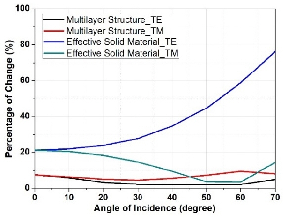
Stability of the transmitted power of an optimized multilayer structure with an effective solid-type radome in the X-band.
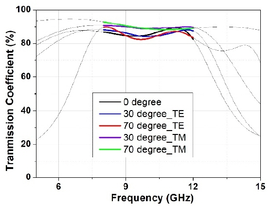
Optimized transmission coefficient of the multilayer structure for the X-band.
To give a more effective decision, the same design properties of the multilayer radome are applied in the Ku-band (12–18 GHz). Table 3 shows the same result to demonstrate that ACOR has better performance than PSO. Fig. 6 illustrates that the stability in the transmitted power of the optimized multilayer structure is less than 10%, which is outstanding compared with that of the effective solid radome. Fig. 7 shows the transmission coefficient of the optimized radome for the TE and TM modes in the Ku-band.

Comparison of the 30 execution times between ACOR and PSO for the Ku-band frequency
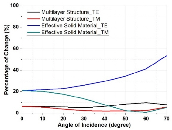
Stability of the transmitted power of the optimized multilayer structure with an effective solid-type radome in the Ku-band.
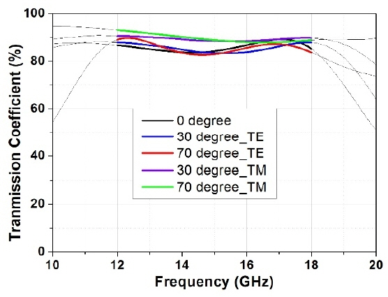
Optimized transmission coefficient of the multilayer structure for the Ku-band.
According to the computed result, ACOR gives a promising value in optimizing multi-objective problems applied in the electromagnetic multilayer radome design.
IV. Conclusion
A comparative study of two metaheuristic optimization algorithms, PSO and ACOR, for an electromagnetic multilayer radome design with various angles of incidence (0°–70°) in the perpendicular and parallel polarizations for the X- and Ku-bands was presented. The simulation results obtained by ACOR were compared with those of a trusted optimization, PSO. The results strongly confirm that ACOR can be useful in the electromagnetic multilayer radome characteristic optimization. The stability for the transmission coefficient of the optimized structure is also guaranteed by ACOR. In future works, the ACOR algorithm will be improved to solve more complex frequency-selective surface design optimization problems such as the 3D frequency-selective surface screen design.
Acknowledgements
This work was supported by the Agency for Defense Development under contract (No. UD170044JD).
References
Biography
Trung Kien Nguyen received his B.S. degree in information technology, University of Engineering and Technology from Vietnam National University, Hanoi, Vietnam, in 2013. He is currently working toward obtaining his M.S. degree in information and communication engineering from Kongju National University, Cheonan, Korea. His research interest is optimization algorithm in electromagnetics.

Obum Kwon received his B.S. and M.S. degrees in mechanical engineering from Ulsan National Institute of Science and Technology, Ulsan, Korea, in 2015 and 2017, respectively. Since 2017, he has been a researcher for the Agency for Defense Development, Daejeon, Korea. His research interests include composite material structures and periodic electromagnetic structures.

In-Gon Lee received his B.S. and M.S. degrees in information and communication engineering from Kongju National University, Cheonan, Korea, in 2013 and 2015, respectively. He is currently working toward obtaining his Ph.D. degree in information and communication engineering from the same university. His research interest is periodic electromagnetic structures.

Yoon-Jae Kim received his M.S. and Ph.D. degrees in mechanical and aerospace engineering from Seoul National University, Seoul, Korea, in 2005 and 2011, respectively. From 2011 to 2012, he worked as a senior researcher at the Institute of Advanced Machines and Design, Seoul National University. Since 2012, he has been working at the Agency for Defense Development, Daejeon, Korea, as a senior researcher. His research interests include aircraft structures and acoustic, vibration, and periodic electromagnetic structures.

Ic-Pyo Hong received his B.S., M.S., and Ph.D. degrees in electronics engineering from Yonsei University, Seoul, Korea, in 1994, 1996, and 2000, respectively. From 2000 to 2003, he was a senior engineer in CDMA Mobile Research at the Information and Communication Division of Samsung Electronics Company, Suwon, Korea. In 2006 and 2012, he was a visiting scholar at Texas A&M University, College Station, TX, USA, and Syracuse University, Syracuse, NY, USA, respectively. Since 2003, he has worked as a professor at the Department of Information and Communication Engineering, Kongju National University, Cheonan, Korea. His research interests include numerical techniques in electromagnetics, electromagnetic compatibility, and periodic electromagnetic structures.