I. Introduction
Electromagnetic surveying systems are widely used for environmental and engineering studies [1, 2]. In the electromagnetic method, a source is used to produce an incident wave, where interaction between the wave and the investigated object leads to generation of a scattered wave. Data are gathered at the receiver to obtain information to predict the physical properties of the investigated configuration through solving the inverse scattering problem [3].
Inverse scattering problems have several applications in research areas such as archeology, geophysical prospecting, and medical imaging [4, 5]. These types of problems suffer from a limited amount of information about the variables to be estimated [6, 7]. However, solutions to such problems must be accurate to get a reasonable estimate, and a reasonable estimate is mainly affected by the efficiency of the forward problem formulation. Several techniques are available for forward problem formulation, such as the finite-difference and finite-element methods [8, 9] and the boundary element method [10]. However, such conventional numerical methods have limitations, including numerical polarization and dispersion [11, 12], inaccurate representation of decaying fields, and integrals with singularity or hyper-singularity [13, 14]. Thus, one of the objectives of this paper is to provide an accurate forward modeling method that overcomes some of these limitations and difficulties.
Another objective of this paper is to develop an inversion methodology that benefits from the optimal setting of the forward formulation to solve both two- and three-dimensional (2D and 3D) electromagnetic inverse scattering problems in inhomogeneous media. In our approach, the inverse problem is treated as a sampling problem using the simulated annealing method without affecting the nonlinear nature of the problem. Moreover, several simulated annealing algorithms were designed and compared with different case studies to ensure the approachŌĆÖs efficiency in terms of estimation error.
II. Forward Formulation
An efficient forward algorithm for calculating scattered fields from input model parameters (i.e., permittivity and conductivity) is required to solve an inversion problem [8]. Most inversion approaches have a link between the forward and inverse problems in order to evaluate the fitness of the predicted parameters for the proposed model [9].
Forward problem techniques are always based on a previously selected configuration, and the effectiveness of the forward configuration strongly influences the efficiency of the inversion approach. Approaches used for modeling electromagnetic forward problems fall into two main categories: mesh-based and meshless approaches [15].
Most commercial simulators use mesh-based approaches to solve forward problems. Mesh-based approaches have several limitations because they must truncate the domain of computation, which introduces unphysical nonreflecting boundaries [16, 17]. They also create a large grid with too many cells to get an accurate solution, especially if the structure is lossy and contain evanescent fields [18]. These limitations mean that these approaches suffer from long simulation times [19].
Meshless approaches can be used for the forward formulation of MaxwellŌĆÖs equations through the expansion of fields using Fourier transform or Gauss-Hermite functions [20]. However, these approaches involve many integrals that have to be evaluated numerically, so they are computationally expensive. In this paper, a meshless approach will be adopted that avoids such integrals; therefore, reducing the computational complexity of the solution, and that locates accurate estimates of the model with a reasonable error margin.
1. Two-Dimensional Problem
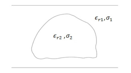
In this paper, we will consider the 2D model shown in Fig. 1, where an object of permittivity ╔ør2 and conductivity Žā2 is buried inside a slab with permittivity ╔ør1 and conductivity Žā1. For the 2D problem, the electric polarization current can be represented as [21]:
(1)
where Ei(x, z) is the incident electric field, (x, z) is the Cartesian coordinate of an observation point, (xŌĆ▓, zŌĆ▓) is the Cartesian coordinate of the polarization current, and L is the slab thickness.
G = i 4 H 0 ( 1 ) ( x , z , x ŌĆ▓ , z ŌĆ▓ ) H 0 ( 1 ) ( . )
where
For the 2D case of one-layer slab with an object inside it, we can write Q(x, z) as:
where ╬®(s) is the indicator to classify the object from the slab. ╬®(s)=0 indicates the slab while ╬®(s)=1 indicates the object, and
where
k 0 = w ╬╝ 0 ╔ø 0
One approach to solve this problem is to use Fourier transform and {Žłn} orthogonality properties [23], but by this representation, overlap integrals in kx and n are required. These integrals have a very high computational cost. To avoid this cost, we propose another approach that avoids all overlap integrals: the point-by-point approach. In this approach, we get the scattererŌĆÖs polarization of current expansion coefficients an(kx) in the form of:
(9)
where
k z = k 0 2 - k x 2
(10)
Here, integrals are approximated to Ōłæ with a step ╬┤kx. Now we can define a linear system to get the estimated current expansion coefficients to be:
where
and
and
Current expansion coefficients a can then be computed as:
Once we compute the coefficients {an(kx)}, the scattered electric fieldŌĆÖs distribution is obtained at the receiver for a given kx as:
The 2D problem was modeled by frequency domain finite element analysis using the COMSOL Multiphysics software package. The incident field was a linearly polarized plane wave normalized by
i 2 k z
2. Three-Dimensional Problem
In order to extend the proposed solution to the 3D case, the model used in this paper is presented in Fig. 3, where a sphere of permittivity ╔ør2 and conductivity Žā2 is buried inside a box with permittivity ╔ør1and conductivity Žā1. Here, the scatterer polarization current expansion coefficients an(kx, ky) can be written in the form of [24]:
(17)
where
k z = k 0 2 - k x 2 - k y 2
(18)
where integrals are approximated to Ōłæ with steps ╬┤kx and ╬┤ky. By this representation, all overlap integrals in kx, ky, and n are avoided. This reduces the computational cost dramatically. Now we can define a linear system to get the estimated current expansion coefficients to be:
where
Then the current expansion coefficient, a, can be computed as:
Once we compute the coefficients {an(kx, ky)}, the scattered electric fieldŌĆÖs distribution is obtained at the receiver for a given kx and ky as:
The 3D problem was modeled by frequency domain finite element analysis using the COMSOL Multiphysics software with the same conditions and structure shown in Fig. 3. The calculated (using Eq. (24)) and the simulated (using COMSOL) scattered electric field results were compared at 11 wavenumbers (kx =0,0.11 k0,ŌĆ”.,1.1 k0 and ky = 0,0.11 k0,ŌĆ”1.1 k0).
III. Inversion Approach
The inversion technique aims to estimate the physical variables that tolerably fit the scattered data [25]. In electromagnetic problems, responses from the model in the form of a scattered electric field are nonlinear functions of the proper modelŌĆÖs physical variables [26]. The physical variables of the model used can be predicted using nonlinearized or linearized inversion algorithms [27]. In this paper, the inversion approach uses the developed forward solver repetitively as an integral part of the inverse technique.
The proposed approach rearranges the nonlinear inversion process to find a solution of a set of linear equations. However, the final inversion equation is still nonlinear. This is done by modeling the electromagnetic inverse problem as a global optimization problem, where the multivariable function of the problem is iteratively minimized using the simulated annealing technique [28, 29].
Using simulated annealing in the inversion methodology allows for a straightforward insertion of the a priori information into the forward model. Furthermore, the proposed inversion approach does not require the starting solutions to represent good estimates of the exact configuration of the structure. In this paper, optimization of the unknown electrical variables is conducted through an objective function, Ob, in the form of:
where
E m n E c n
where ╔ørm and Žām are the relative dielectric constant and conductivity of the mth object. The simulated annealing algorithm starts with initial estimates for the objectŌĆÖs electrical properties, driven by a priori knowledge of the possible range of the modelŌĆÖs physical parameters; this is called the current estimates.
The algorithm then generates new estimates with a random distance from the current estimates in the search space. This distance is selected by a probability distribution with a scale depending on the current temperature. Afterwards, the algorithm determines whether the new estimates are better or worse than the current estimates by evaluating the objective function, Ob, for both the current and the new estimates.
If the objective function value of the new estimates is less than that of the current estimates, the new estimates are accepted in place of the current estimates. However, to avoid being trapped in the local minima, the algorithm can still accept new estimates that raise the value of the objective function in place of the current estimates. Thus, the new estimate of the objectŌĆÖs electrical properties is accepted either if it is better than the current estimate or if it is worse than the current estimates but with a certain probability value. This probability is controlled by two main factors: the temperature and the difference between the current value and the new value of the objective function, and it can be defined by an acceptance function:
where Obnew is the objective function value of the new estimates, Obcurrent is the objective function value of the current estimates, and T is the current temperature. By accepting worse estimates based on an acceptance function, the algorithm will be able to explore globally for more possible solutions. However, during the algorithm iterations to find the best estimate, the simulated annealing algorithm systematically decreases the probability of accepting worse estimates by applying the designed cooling schedule Tc, wherein the temperature decreases, leading to a lesser acceptance probability. In this paper, three simulated annealing cooling schedules are designed, implemented, and compared for performance. The first is exponential, where the cooling schedule is given by [30]:
where c = 1, 2, 3 . . . is the iteration number, T0 is the initial temperature, and a is the cooling rate. The second is called the fast cooling schedule and is given by:
The third is called the Boltzmann cooling schedule, and is given by:
Here we use T0=100┬░C and a = 0.95 for the three cooling schedules. In this paper, the different simulated annealing techniques were used to minimize the error between the predicted and computed electrical variables, aiming to reach an optimum error of 0%. However, if the algorithm cannot reach that goal, stopping criteria of 10,000 iterations is implied. After the stopping criterion is achieved, the algorithm outputs the results that realize the value nearest to the optimum.
IV. Results and Discussion
In this paper, for both the 2D and 3D problems, we selected 10 possible structures from which to construct 10 case studies. Table 1 summarizes the possible permittivity and conductivity ranges of these structures. To measure the efficiency of the proposed inversion technique, we identify a wideness factor that quantifies the wideness of each physical parameter range around the average. The wideness factor represents a priori knowledge for each structure and can be defined as:
(31)
To test the inversion approach in terms of efficiency, values of the relative permittivity and conductivity of 10 structures were selected to reflect relatively large wideness factors. The inversion approach was then applied to the 10 case studies constructed from the available 10 structures. The case studies are summarized in Table 2. To analyze the results of the inversion approach in terms of error, we defined a term for relative percentage error er as follows:
In order to evaluate the performance of different cooling schedules in terms of error, we calculated the error margin over 100 times for each physical parameter for each cooling schedule as follows:
1. The Two-Dimensional Problem
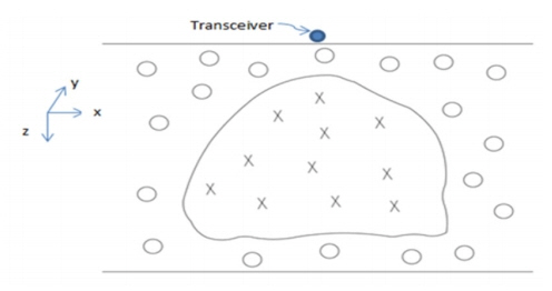
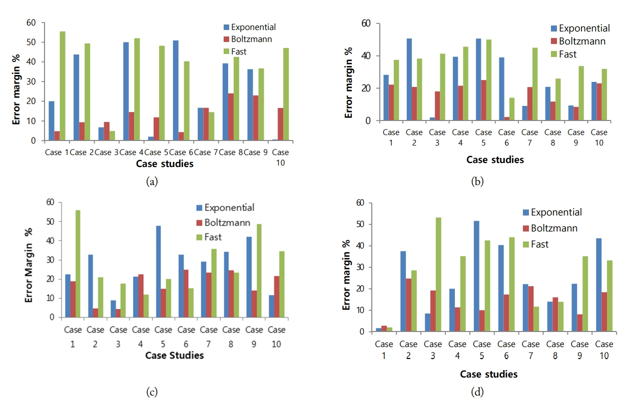
Fig. 5 illustrates the 2D inhomogeneous media used in this paper. The electromagnetic transmitter and receiver are positioned at the same point just above the top of the media with a frequency of one megahertz. For forward problem calculations, circles in Fig. 5 represent an indication of selected points within the slab, while the Xs represent an indication of the selected points inside the object. The inversion problem is formulated to estimate four electrical properties of both the slab and the object (i.e., ╔ør1,Žā1,╔ør2,Žā2) given the measured scattered electromagnetic fields at K wavenumbers, with K = 11. The three proposed simulated annealing algorithms were evaluated for the ten 2D case studies, and an error margin, eg, against each case study is shown in Fig. 6 where a comparison is made between each cooling schedule per electrical parameter.
Results in Fig. 6 show that, among the three implemented cooling schedules, the Boltzmann cooling schedule achieves eg Ōēł25% as the worst value of the tested case studies. On the other hand, the fast and exponential cooling schedules provide eg > 40%, in some tested case studies, although they achieve lower eg values than the Boltzmann cooling schedule in other cases. From the obtained results, it can be concluded that using the Boltzmann cooling schedule within the inversion methodology provides a relatively low error margin for most of the estimated parameters compared with the other cooling schedules. Also, as the eg% resulting from the Boltzmann cooling schedule are far lower than the wideness factors of the physical parameters, it can be concluded that the inversion methodology achieves better a posteriori knowledge about each physical parameter than the a priori knowledge. The estimated physical parameters can therefore be interpreted correctly after applying the proposed inversion methodology as its estimated values are within its specified range.
2. The Three-Dimensional Problem
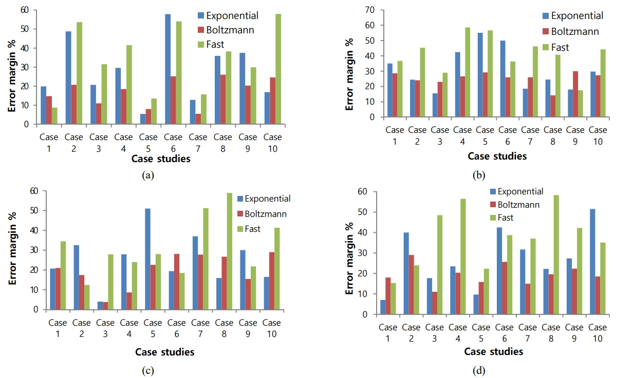
Fig. 7 illustrates the 3D inhomogeneous media presented in this paper. For forward problem calculations, spheres represent an indication of selected points within the box, while pyramids represent an indication of the selected points inside the object. Here, the transmitter and receiver are located at the same place on top of the media with a frequency of 1 MHz. The inversion problem is formulated to estimate four electrical properties for both the object and the box (i.e., ╔ør1,Žā1,╔ør2,Žā2) given the measured scattered electromagnetic fields at K wavenumbers, with K = 11. For the presented inversion approach, three simulated annealing cooling schedules were assessed for the 10 proposed 3D case studies. An error margin, em, for each case study is presented and compared in Fig. 8, where a comparison is made between each cooling schedule per electrical parameter.
Results reveal that eg for the Boltzmann cooling schedule does not exceed 30% in the worst case among the investigated case studies. The exponential and fast cooling schedules result in a higher eg of > 50% in the worst-case although they may give a lower eg than the Boltzmann cooling schedule in other cases. It can therefore be concluded that, for the 3D problem, applying the Boltzmann cooling schedule within the inversion methodology provides better a posteriori knowledge than a priori knowledge. This is due to the relatively low eg of the estimated value compared to the wideness factor of the physical parameters, which in turn results in the correct interpretation of the investigated parameters.
V. Conclusion
In this paper, an inversion scheme using the simulated annealing technique has been presented to solve both 2D and 3D inhomogeneous nonlinear inverse scattering problems. First, a forward model was developed using a meshless formulation to solve MaxwellŌĆÖs equations. The proposed forward model was designed to reduce computational complexity, compared with conventional methods, and therefore to take less time to perform repetitive computations. Second, an inversion approach was proposed to estimate the electric properties of the investigated 2D and 3D scatterers using information about the electromagnetic source and scattered data. Three simulated annealing cooling schedules were evaluated against 2D and 3D case studies. The results show that using the Boltzmann cooling schedule gives a worst-case error of 25% for the 2D case studies and 30% for the 3D case studies. The posterior knowledge of the electric properties of the investigated scatterer is far better than the prior knowledge. These results reveal the efficiency of the presented inversion approach in providing relatively good estimates about the investigated electric properties of the scatterer within their natural range, taking into account the non-uniqueness nature of such problems. The proposed approach can be used to solve the inverse scattering problem for inhomogeneous media in different areas of research.


