A Cross-Joint Vivaldi Antenna Pair for Dual-Pol and Broadband Testing Capabilities
Article information
Abstract
The non-standalone 5G antenna wireless communication standard and devices operating under Wi-Fi 5, 6, and 6E operate at the 3 GHz frequency bands and above. With the increasing demand for these devices and technologies, it is crucial to test them rapidly and economically for commercial usage. This paper presents a dual-polarized Vivaldi antenna for the over-the-air (OTA) measurement of wireless communication devices used in the 3–7 GHz band. The dual-polarization performance is realized by vertically intersecting two planar Vivaldi antennas and soldering them at the back end. A three-step 1/4 wavelength balun is applied to the input for the wideband impedance matching of the antenna, which is attached to a Teflon holder for easy mounting. It has excellent performance and is designed to be manufactured at low cost. The fabricated antenna was tested in an anechoic chamber and showed S11 less than −10 dB from 2.63–7.15 GH, and a realized gain of more than 5 dBi from 3 GHz and above. A measured half-power beam width of more than 60° was realized with symmetric E/H-plane. Much of the required symmetry was achieved with the designed Teflon holder. The antenna has a measured cross-polarization discrimination of better than 15 dB across the entire operating bandwidth.
I. Introduction
Existing 4G LTE (IMT-Advanced) and most Wi-Fi communication equipment use the 3 GHz frequency band or below, which is ideal for long-range and secure mobile and broadband communication. However, the increasing number of mobile service users and the large amounts of data consumption mean that the frequency resources are approaching a near-saturation point, which could result in traffic congestion [1]. Consequently, frequency bands above 3 GHz are attracting attention as a new radio wave resource. A typical example is the 5G non-standalone (NSA) standard. The 5G NSA uses a 3–6 GHz frequency band known as “sub-6 GHz,” which provides a higher bandwidth and higher speed than 4G LTE. It effectively resolves existing traffic problems and is also being used in core technologies of the fourth industrial revolution systems, such as the Internet of Things, virtual reality, and augmented reality [2]. The wireless communication standards, IEEE 802.11ac (Wi-Fi 5) and the subsequent 802.11ax (Wi-Fi 6), also use the 5.7–5.9 GHz band range to enable faster data processing than the conventional 2.4 GHz band [3]. The new Wi-Fi 6E will also support frequencies in the sub-6 GHz spectrum [4, 5].
Signal path loss is a common occurrence with the use of higher frequency bands. Multiple-input and multiple-output (MIMO) antennas can reduce path loss with beamforming techniques, which use multiple antennas to focus the beam in the desired direction [6]. However, the conditions for measuring their performance can be problematic in terms of long measurement times and inaccuracies with power amplifier and cable loss calibrations. Thus, the conventional measurement method cannot be used for active measurement in a beamforming scenario [7]. A variety of measurement scenarios can be actively addressed, and the measurement time of the MIMO antenna can be effectively shortened using certain systems. One example is the over-the-air (OTA) measurement system. In fact, most radiation performance tests and evaluations are conducted using the OTA measurement, including for 3G and 4G devices [7, 8].
To perform OTA measurements rapidly and accurately, certain requirements are needed for the antenna measuring system. This includes a wide bandwidth to measure a vast array of devices at various frequency bands, a wide beamwidth, and symmetrical radiation patterns capable of uniformly investigating the device under test in both the far and near field. Other considerations include dual polarization with excellent cross-polarization discrimination (XPD) and a highly suppressed side-lobe level with stable gain across the operating bandwidth. In addition to these electrical performances, the antenna should be inexpensive to allow for mass production and should be small in size and lightweight for easy installation.
Existing antennas for OTA measurements, such as the quadridge horn antenna, have certain significant drawbacks [9–12], including the tendency to be bulky and expensive to develop and install. However, in [13–17], two flat Vivaldi antennas were orthogonally coupled to construct a dual-polarized antenna with excellent performance. The Vivaldi antenna is easy to manufacture, inexpensive to develop, and light enough to be attached to the chamber, while it also achieves good broadband impedance matching and radiation performance.
This paper proposes a dual-polarization Vivaldi antenna for OTA measurement in the 3–7 GHz bandwidth. A system that implements a dual-polarization mode through the vertical cross-coupling of two single Vivaldi antennas is convenient since it allows for measuring all horizontal and vertical polarizations without having to reposition the antenna, while the measurement time can also be shortened.
Section II outlines the design and optimization approach for two identical Vivaldi antennas, their feed mechanisms, and the dual-polarization implementation technique. A mounting structure to attach the antenna to the OTA chamber holder is also developed. Section III then outlines how the optimized antenna with its holding brackets was manufactured and tested. Here, a brief description of the antenna manufacturing process and the measurement results are provided and discussed. The measured antenna operates from 2.63–7.15 GHz, representing a fractional bandwidth of 92% at −10 dB S11. An antenna gain ranging from 5–10 dBi was also recorded across the operating bandwidth with a half-power beamwidth (HPBW) of more than 60° with E/H-plane symmetry and an XPD of better than −15 dB. The proposed design’s performance was also evaluated for its designs in the existing research. Section IV concludes the contents of Sessions II and III, and refers to the possibility of additional development.
II. Antenna Design
As shown in Fig. 1, the Vivaldi antenna was designed in terms of a microstrip printed circuit board (PCB). The designed PCB is a 0.76-mm-thick Taconic-35 dielectric substrate, with a dielectric constant (ɛr) of 3.5 and a low loss of 0.0016. A pattern was designed using copper foil on both sides of the substrate. On the front of the antenna, a tapered slot pattern was designed with an etched narrow slot gradually expanding to form an opening. On the back, a quarter-wave transformer-type balun that could supply power was designed with some consideration of the difference in impedance between the input terminal and the antenna.
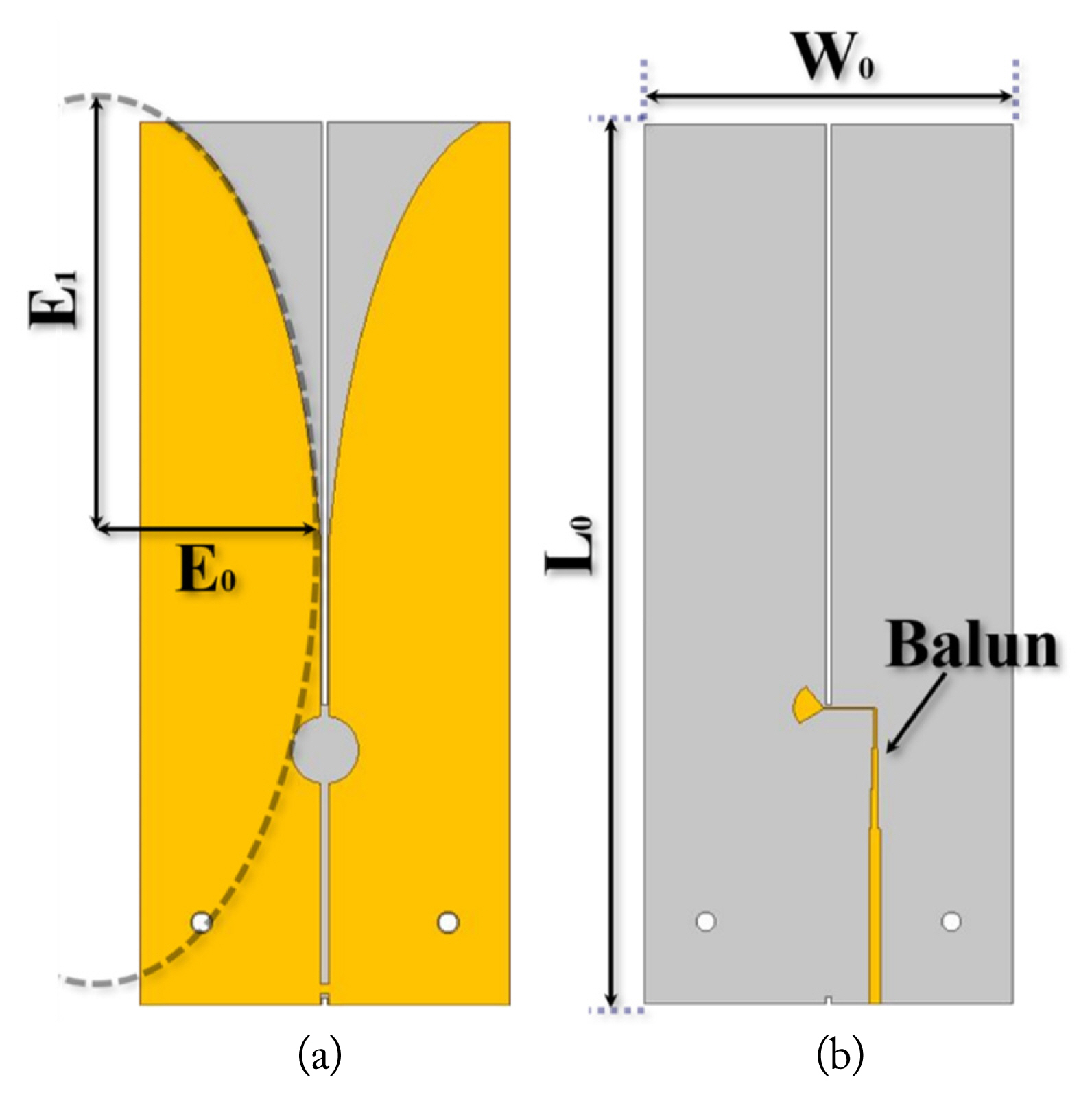
Design parameters of the designed Vivaldi antenna model: (a) front and (b) back.
According to [18], the energy of the wave fed through the balun is transferred to the narrow slot and then follows the tapered slot pattern to the opening. At this point, polarization occurs at the ends of both slots, and charges are generated. Coupling with the charge then occurs, and electromagnetic waves are subsequently radiated. The space between the slots is wider, and the wavelength of the coupled electromagnetic waves is longer. The change in the length of the wavelength means that the frequency characteristic of the electromagnetic wave also changes. Electromagnetic waves with various frequency characteristics radiate from the narrow slot to the opening such that the wavelength of the electromagnetic waves can be induced by using the width of the slot to secure the desired frequency band.
Additionally, the circular slots behind the narrow slots induce waves to a couple in the circular slots as they flow in a reverse direction. Here, unnecessary backside radiation can be reduced, and the energy can be concentrated in one direction to increase gain.
In Fig. 1, W0 is the width of the antenna and is the section where the slot is widest. This radiates the longest wavelength electromagnetic wave corresponding to the minimum cutoff frequency (fmin). According to [18], W0 is recommended to be half of the guided wavelength at fmin:
where λg is the guided wavelength and c is the speed of light. With fmin = 2 GHz and ɛr = 3.5, λg becomes 80 mm. Thus, we assigned W0 = 40 mm, half of λg, in the initial Vivaldi design.
Meanwhile, L0 is the length of the antenna and was initially designed to be 80 mm. However, if the antenna is installed on the holder, the performance may be changed. And the antenna was thus designed to be longer than the holder area. So, L0 was changed to 120 mm. The curved surface of the slot was designed by drawing an ellipse using the lengths of E0 and E1.
As shown in Fig. 2, the balun on the backside applies the quarter-wave transformer-type impedance matching method, which is used to reduce reflection due to the impedance difference between the input terminal and the antenna [19, 20]. The length of L1 was 30 mm, and that of L2–L4 mainly reflects the impedance of the intermediate frequency band since the characteristics of the passing frequency are reflected. Therefore, the length of the line was 6.5 mm, which is slightly less than 8 mm, around 1/4 of the length of the guide wavelength at 5 GHz, the intermediate frequency in the 3–7 GHz bandwidth. L5 was 8 mm.
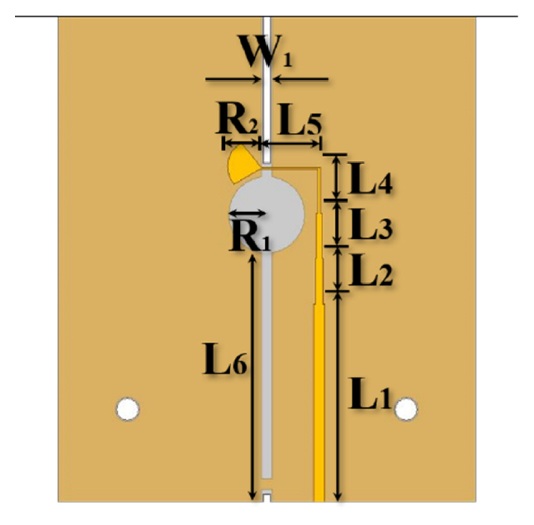
Detailed parameters of the quarter-wave transformer balun.
Also, the line width starts at 1.70 mm at the input (L1), passes through the narrowing line in three stages (L2–L4), and decreases to 0.25 mm immediately before the fan balun (L5). The balun provided the most appropriate impedance between 50 Ω (L1) of the input stage and the maximum impedance of 125 Ω (L5) and increased the impedance stepwise. The radius R1 of the outer circular slot was 5.5 mm, the length of the fan-shaped balun R2 was 5 mm, and L6 was 37 mm.
However, as Fig. 3 shows, when W0 and L0 were 40 and 120 mm, respectively, the antenna resonated in the 3.2–8.0 GHz bandwidth. Meanwhile, the gain decreased to under 5 dBi in the band below 4 GHz. This issue is disadvantageous for measuring 5G NSA in sub-6 GHz and wireless communication standard devices in the 5.725–5.875 GHz range.
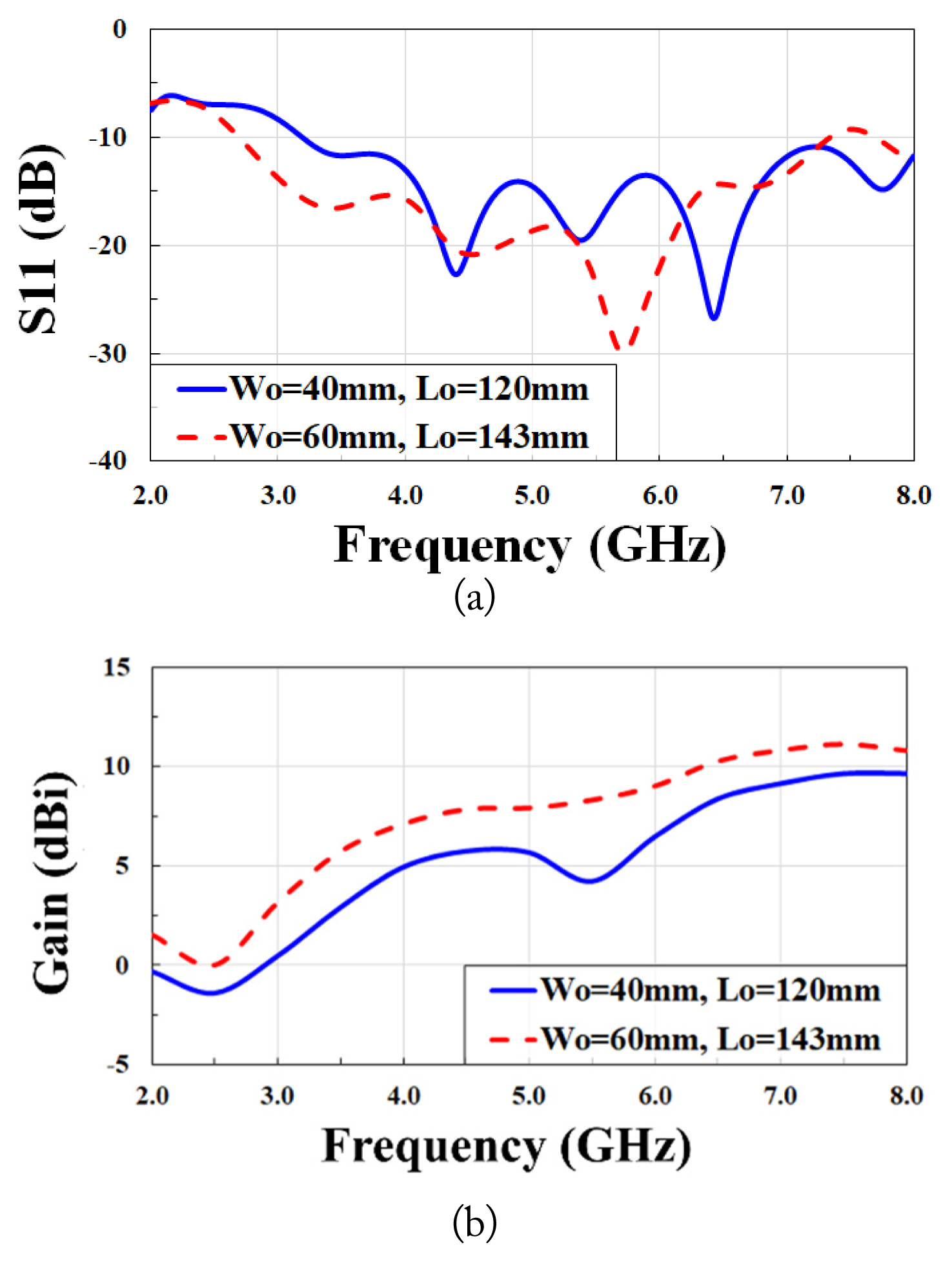
Comparison of the simulation results when changing W0 and L0: (a) S11 and (b) gain.
Figs. 4 and 5 show the parametric study results of S11 and antenna gain by altering W0 and L0, respectively. As shown in Fig. 4(a), the increase of W0 shifts fmin to a lower frequency. The gain slightly increases as the antenna size increases (Fig. 4(b)). The gain dip is also observed at 5.5 GHz. This is due to the destructive interference between the main aperture radiating and minor feed radiating components. To alleviate this dip, L0, the antenna length, is increased to provide a smoother transition along with the feed [21]. As can be seen in Fig. 5(a) and (b), varying L0 hardly affects S11 but improves the gain and reduce the gain dip at 5.5 GHz. When W0 and L0 were increased to 60 mm and 143 mm, respectively, the antenna bandwidth of 2.69–7.34 GHz could be secured. While optimized antennas tend to be larger, they are still comparatively small in size and also tend to have an excellent performance. The parameters of the final designed antenna are detailed in Table 1.
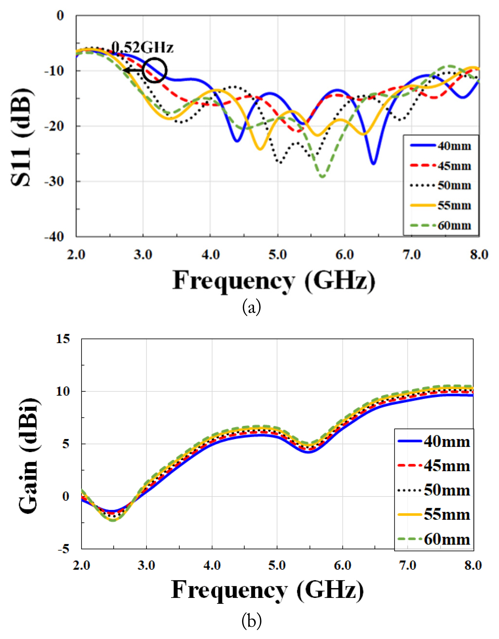
Change in simulation value by varying W0: (a) S11 and (b) gain.
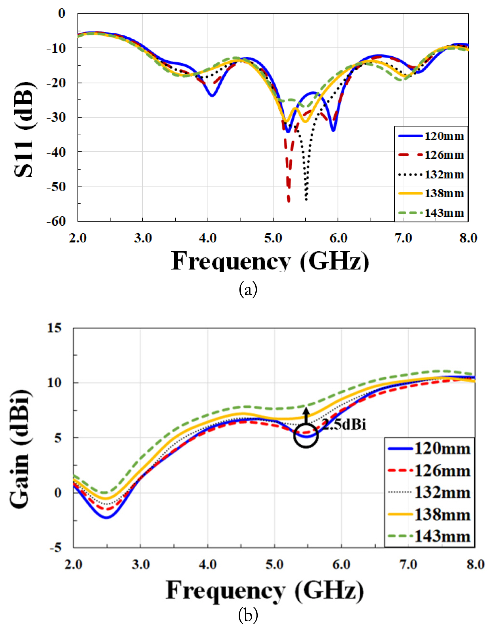
Parametric study by varying L0: (a) S11 and (b) gain.

However, the designed single Vivaldi antenna only supports horizontal polarization, which means that it cannot implement a dual-polarization mode. Therefore, two vertically cross-combined Vivaldi antennas were implemented to provide a dual-polarization mode, as shown in Fig. 6.
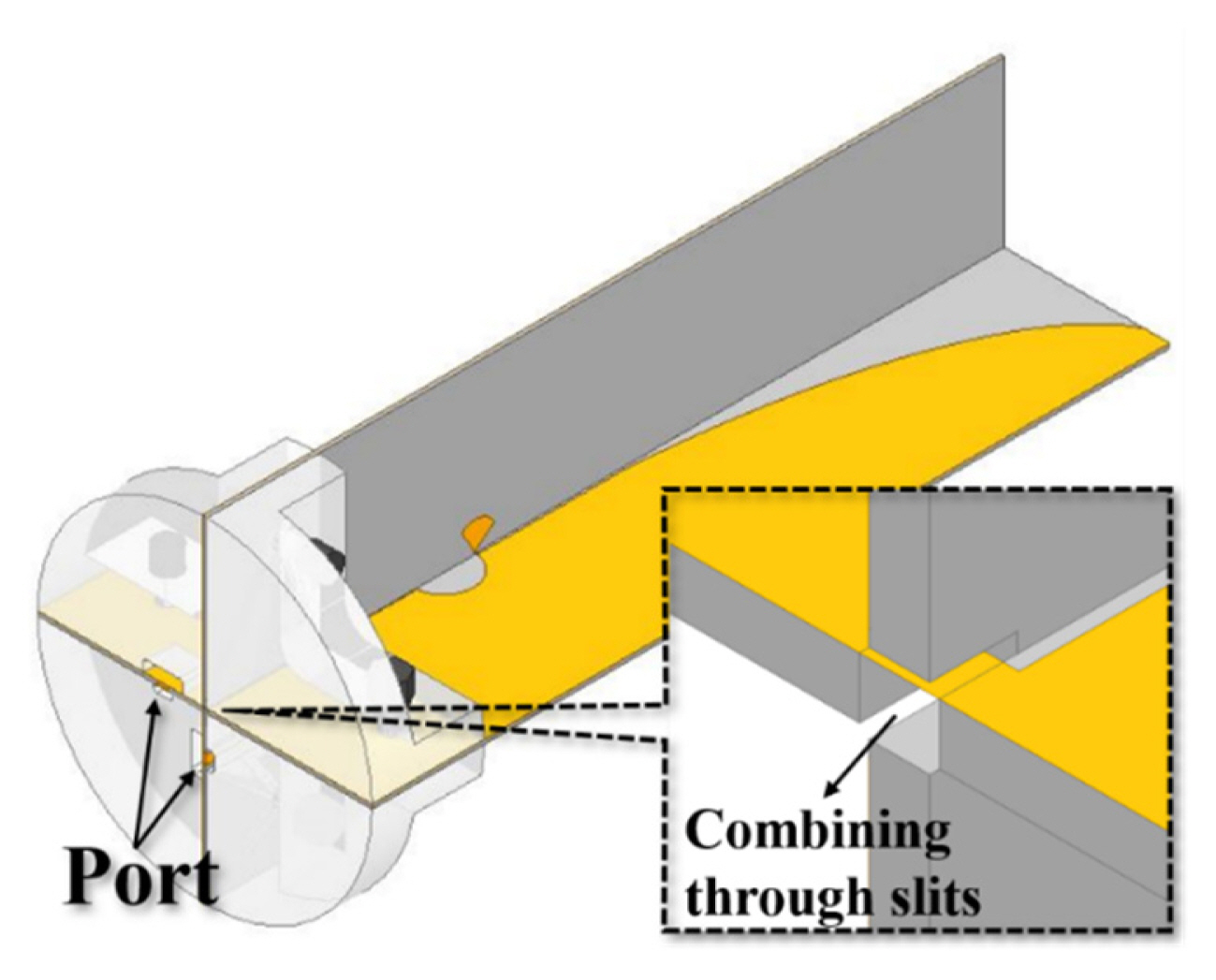
The designed dual-polarized Vivaldi antenna.
Each antenna was designed with a slit in the intersecting part. W1 is the slit thickness, which was 0.85 mm. The W1 was designed with some consideration of the thickness of the antenna substrate, which was 0.76 mm.
The antenna was vertically cross-combined through this slit, and a mounting holder was used to install the measuring antenna in the OTA chamber. The holder was made of Teflon and had non-conductivity and a low dielectric constant, which meant that the effect on the antenna could be minimized while it was light, inexpensive, and easy to process and fabricate. Four separate Teflon blocks were wrapped around the antenna, and the Teflon bolts were inserted through the holes to secure the antenna to the OTA chamber frame.
Fig. 7 shows a comparison of the simulated S11 and gain values, depending on the design process for the antenna. Fig. 7(a) shows how the antenna mounted on the holder was able to secure the 2.56–7.15 GHz band range. The bandwidth was around 0.4 GHz wider than a single Vivaldi antenna, while the gain increased more in the 3–6 GHz band range. Overall, a sufficient bandwidth of 3–7 GHz and a gain of over 5 dBi could be secured.
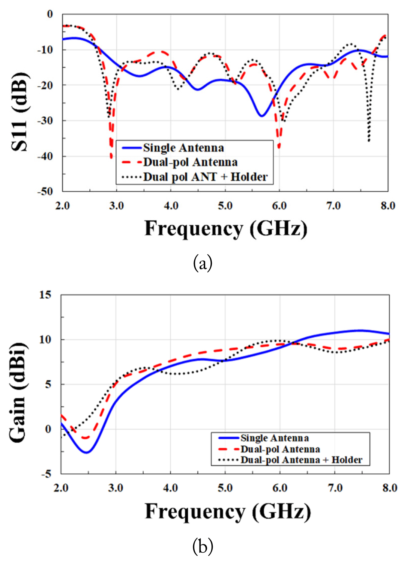
Comparison of the simulation results according to the design process: (a) S11 and (b) gain.
This antenna presented the final design for the dual-polarized Vivaldi antenna for OTA measurement. The detailed simulation results are presented in Fig. 8. The bandwidth of each port of the antenna was 2.56–7.15 GHz. Fig. 8(c), (d), and (e) show the emission patterns in the 3, 5, and 7 GHz bands, respectively. Symmetry exists on the left and right, ensuring a maximum beamwidth of 70° in the 3 GHz band, while the beamwidth gradually decreases as the frequency increased. The radiation pattern maintained a wide HPBW of over 60°.
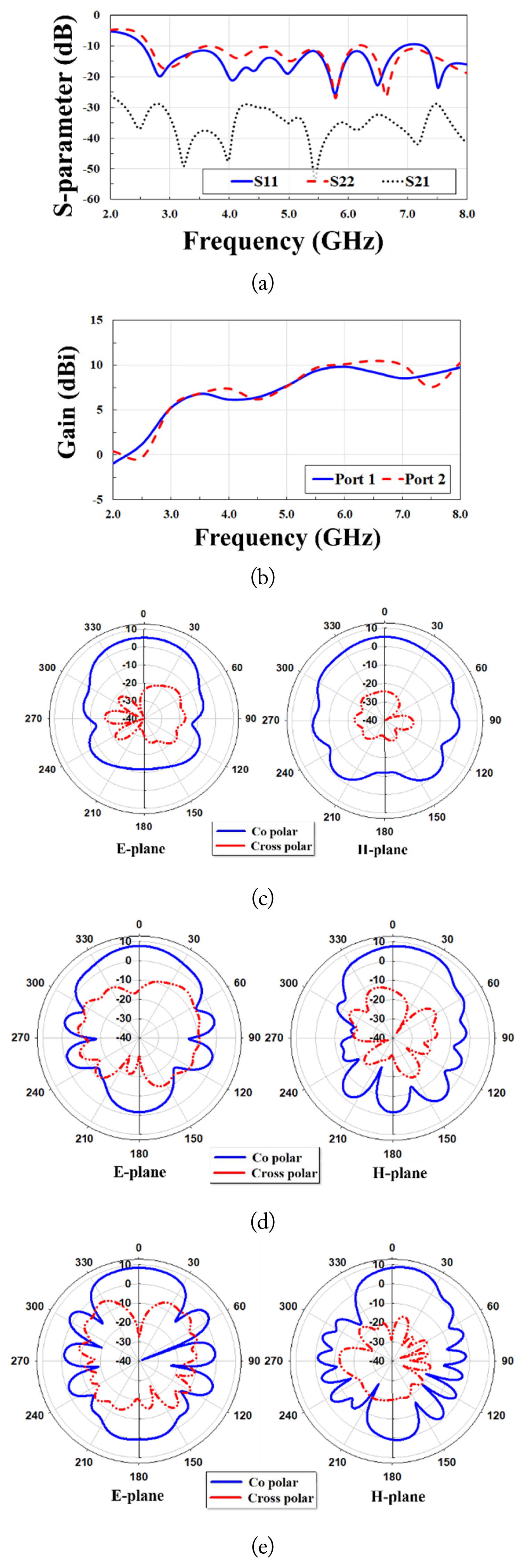
The simulation results of the designed dual-polarized Vivaldi antenna: (a) S-parameters, (b) gain, (c) radiation pattern at 3.0 GHz, (d) radiation pattern at 5.0 GHz, and (e) radiation pattern at 7.0 GHz.
III. Fabrication and Measurement of Antenna
A dual-polarized Vivaldi antenna was fabricated and measured based on the design outlined in Section II. The measurement results were then compared with the simulation values. The fabrication process was similar to the antenna design method and is shown in Fig. 9.
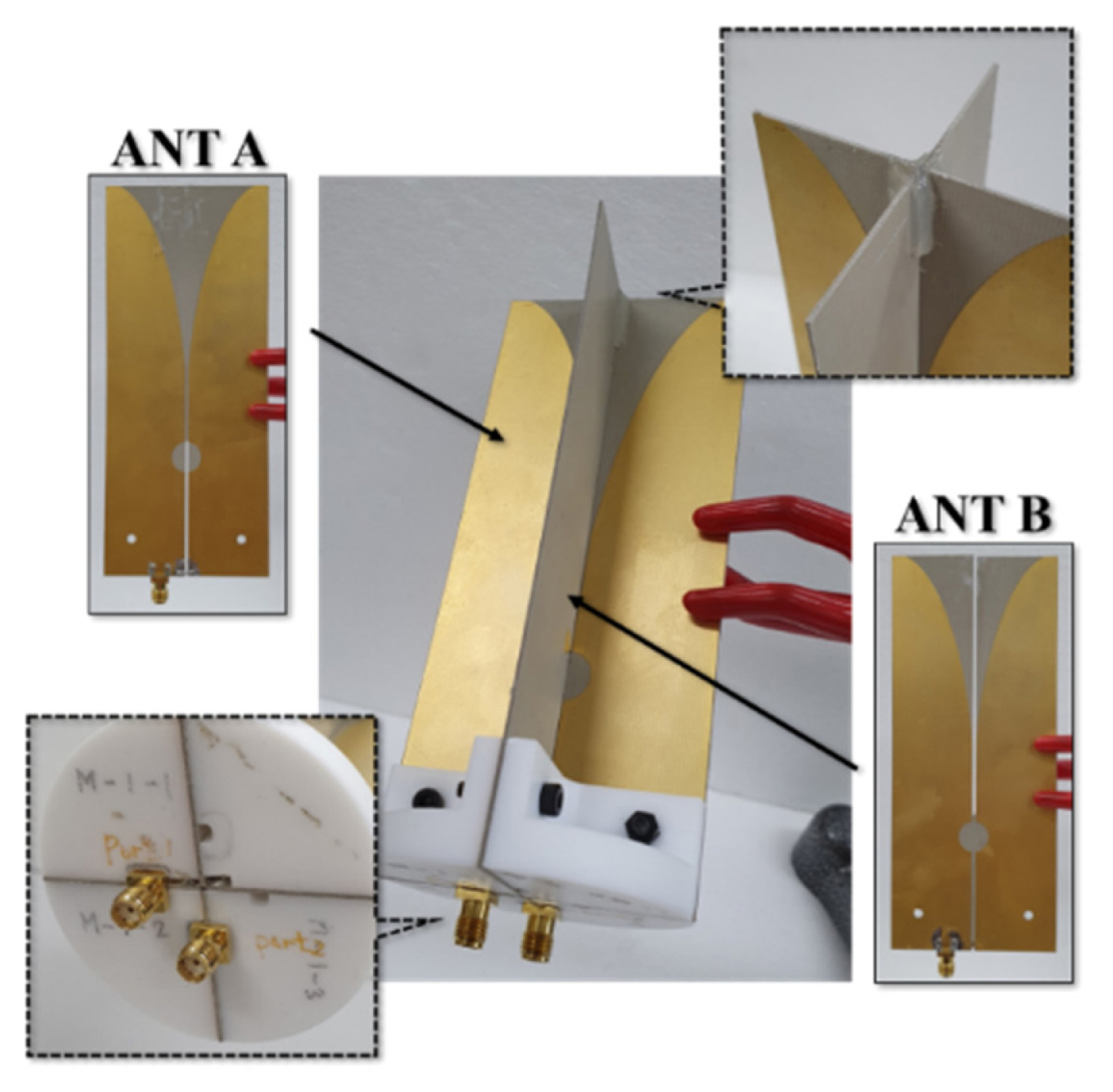
Fabricated dual-polarized Vivaldi antenna.
First, a microstrip PCB single Vivaldi antenna was fabricated. The antenna was 143 mm in length, 60 mm in width, and 0.76 mm in height and incorporated a circuit pattern formed by etching thin copper on both sides of the Taconic-35 dielectric substrate. A SMA (subminiature version A) connector capable of supplying power was soldered to the end of the balun pattern.
Next, a dual-polarized Vivaldi antenna was fabricated by vertically cross-combining two of the single Vivaldi antennas. Both ports of the antenna with the soldered SMA connectors performed dual-polarization modes in the horizontal/vertical direction while acting as inputs and outputs for each other. Following this, a Teflon holder was manufactured, and the antenna was attached to the holder, which allowed the antenna to be attached to the chamber. As such, the cross shape of the antenna could be stably maintained. As Fig. 9 shows, the SMA connector of the antenna was exposed to the bottom surface of the holder, and the cable could easily be connected outside the OTA measurement chamber. After the antenna was attached to the Teflon holder, this dual-polarization Vivaldi antenna for OTA measurement weighed around 116.5 g and measured 143 × 60 × 60 mm. We confirmed the change in the S-parameter that occurred during the manufacturing process using a vector network analyzer (Anritsu MS2038C). With the implementation of the dual-polarization mode, both ports play the role of input and output, and we thus checked the ratio of input voltage to output voltage between both ports. As Fig. 10 shows, the radiation pattern was measured using a chamber capable of far-field measurement (the chamber used was a medium-sized chamber from RAPA Korea). The main measurement section was in the 2–8 GHz range, and the measurement results are shown in Figs. 11 and 12.
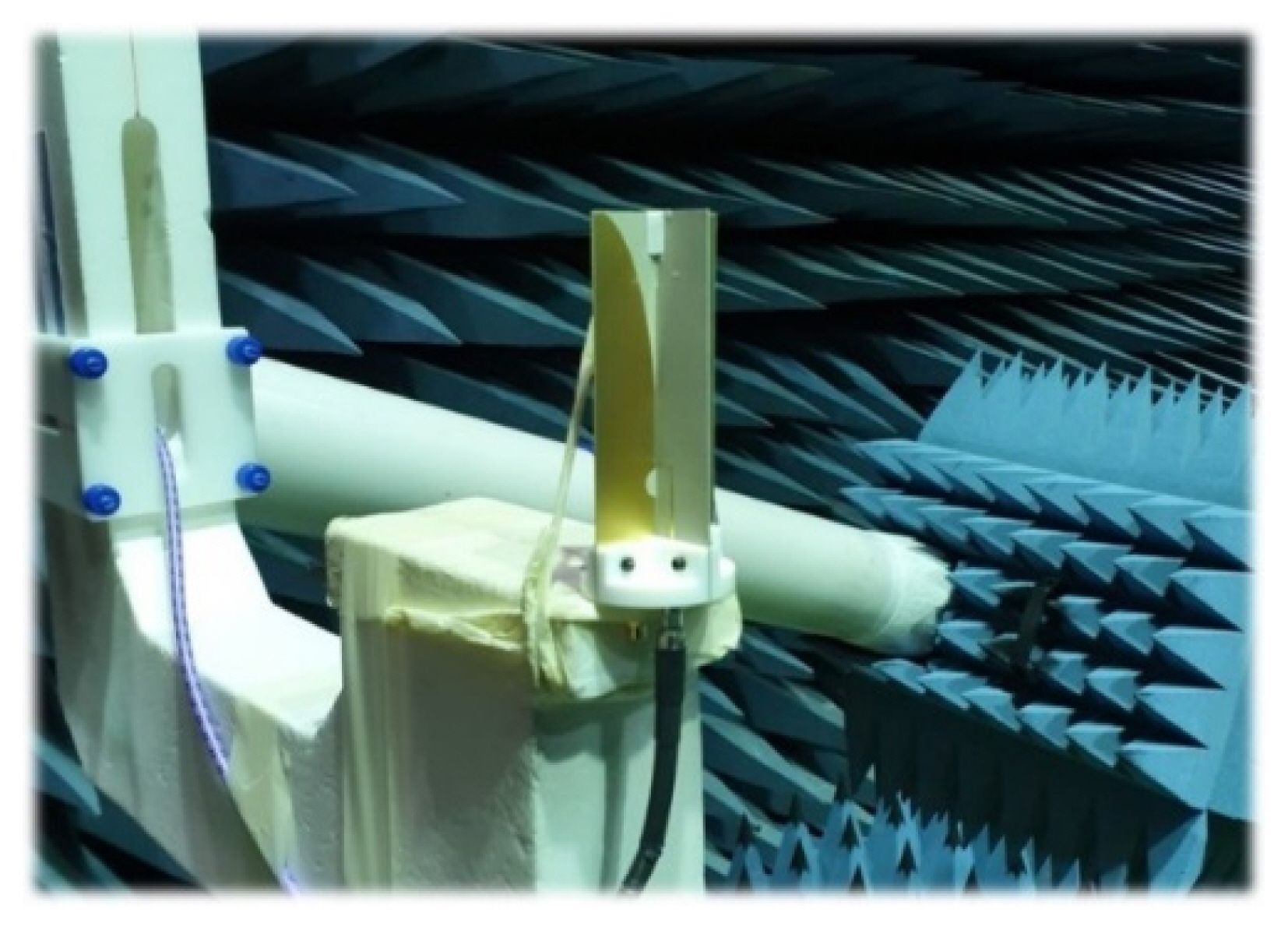
Antenna mounted in anechoic chamber.

Comparison of simulation and measured results: (a) S-parameter, (b) gain, (c) radiation pattern at 3.0 GHz, (d) radiation pattern at 5.0 GHz, and (e) radiation pattern at 7.0 GHz.
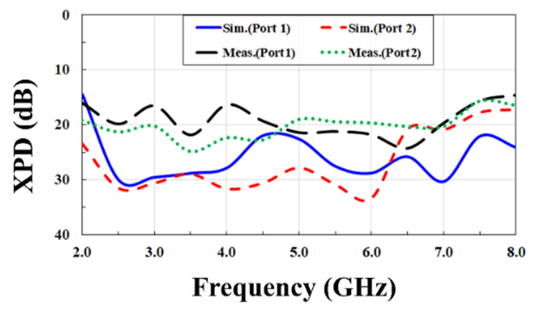
Comparison of cross-pol discrimination.
Here, the S-parameter from each antenna port was measured. It was confirmed that S11 and S22 resonated below −10 dB at 2.56–8 GHz, while the transmission (S12, S21) between the ports was maintained at −30 dB or less in the 3–7 GHz band range. Meanwhile, the antenna gain was, on average, 6.76 dBi in the 3.0–6.0 GHz range (sub-6 GHz) and 9.06 dBi in the 5.725–5.875 GHz range (Wi-Fi 5/6). The beamwidth of the antenna tended to decrease from the 3 GHz band to the 7 GHz band. However, a wide beamwidth of 60° or more could be secured in this range.
All the above results are like those of the simulation, except for the XPD results (Fig. 12). Although it maintained more than 15 dB differences throughout the target frequency range, the measured XPD levels were 5–13 dB less than the simulations. These lower XPD measurement results may be due to unexpected electromagnetic coupling introduced by slight misalignments during antenna fabrication.
Table 2 compares the proposed antenna to other reported dual-polarized Vivaldi antennas. As can be seen, the proposed antenna has a smaller aperture size (1.9λ) and broader beamwidth (≥63°) suitable for multi-probe installation and wide coverage as a testing antenna. On the contrary, the antenna gain is lower due to the broad beamwidth. The bandwidth is relatively narrow, but enough to cover the target communication protocols (e.g., 5G, Wi-Fi 6, IR-UWB).

Comparison of dual-polarization Vivaldi antennas
IV. Conclusion
In this paper, we propose a dual-polarized Vivaldi antenna for OTA measurement that enables high-speed measurement of wireless communication devices in the 3–7 GHz band range. The antenna was designed to resonate below −10 dB S11 from 2.56–7.12 GHz. The radiation pattern had a wide HPBW of over 60°, an XPD of better than −15 dB, and a side lobe level of better than −9.2 dBi across the operating bandwidth. The custom-made Teflon-based holder weighed only 116.5 g, which is extremely light and has the advantages of low manufacturing costs and mass production capacity.
However, additional research is perhaps required. The antenna in this paper was designed and fabricated to ensure a bandwidth of 3–7 GHz. However, when measuring the S11 of the antenna via a vector network analyzer, it was confirmed that the antenna resonated with −10 dB or less, even in the 8–11.6 GHz band range. Since far-field measurement above the 8 GHz band was not performed, the actual gain and radiation pattern could not be confirmed. However, it was confirmed through the simulation that in the 8–11.6 GHz band range, the gain sharply decreased to 0 dBi or less. This is a natural result, as the antenna was designed to ensure a bandwidth of 3–7 GHz. Nonetheless, if additional research is carried out in view of increasing the gain above the 8 GHz band, it would be possible to design an antenna that allows for measurements from the 3 GHz band to the 12 GHz band, which will, in turn, allow for the preparation for non-licensed band usage above the 8 GHz band.
Acknowledgments
This work was supported in part by the Institute of Information and Communications Technology Planning and Evaluation (IITP) funded by the Korea Government (MSIT) (No. 2017-0-00659) and in part by the Basic Science Research Program through the National Research Foundation of Korea (NRF) funded by the Ministry of Education.
References
Biography

Gwang-Hun Jeon received his B.S. degree from Kangwon National University in 2019. He is currently an M.S. researcher in the Department of Electrical and Information Engineering, Seoul National University of Science and Technology. His research interests include electromagnetic measurement and antenna design.

Philip Ayiku Dzagbletey received his B.Sc. in Telecommunication Engineering from KNUST-Ghana in 2013 and his M.Sc. from Hanbat University in 2016. He received his Ph.D. from Seoul National University of Science and Technology in Electrical and Information Engineering in 2020. Much of his research interests relate to microwave transmit array designs, bioelectromagnetic millimeter-wave antenna systems, and circuit designs for industrial and commercial use. He has completed several projects, including 5G antenna measurement systems, millimeter-wave antenna array systems, and wearable fabric antennas.

Jae-Young Chung received his B.S. degree from Yonsei University, Seoul, South Korea, in 2002, and his M.S. and Ph.D. degrees from Ohio State University, Columbus, OH, USA, in 2007 and 2010, respectively, all in electrical engineering. From 2002 to 2004, he was an RF engineer in Motorola Korea. From 2010 to 2012, he was an antenna engineer at Samsung Electronics. He is currently an associate professor in the Department of Electrical and Information Engineering, Seoul National University of Science and Technology. His research interests include electromagnetic measurement and antenna design.