I. Introduction
II. Characteristic Mode Analysis
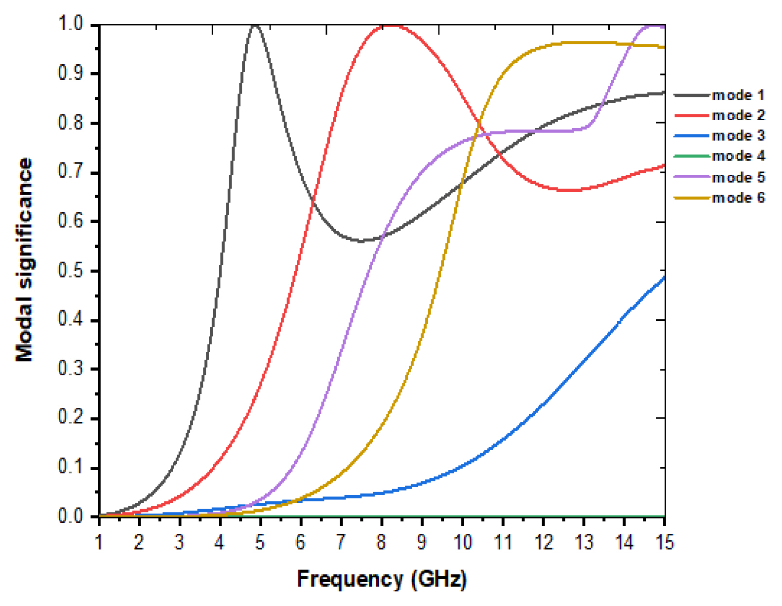
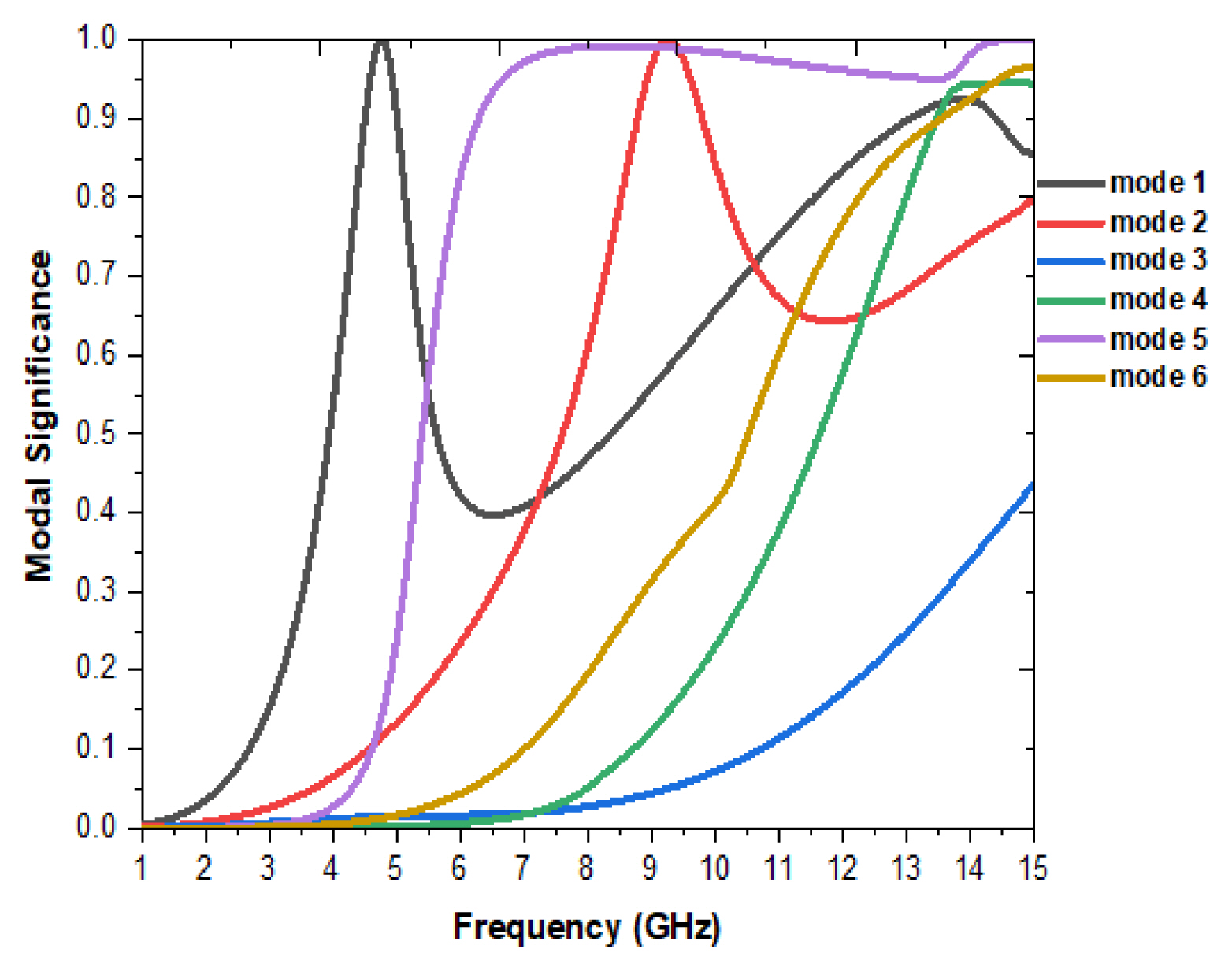
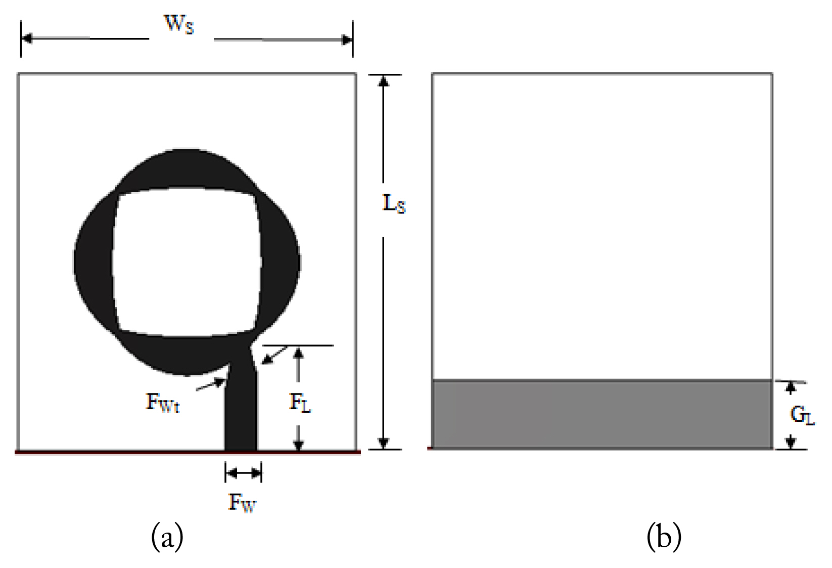
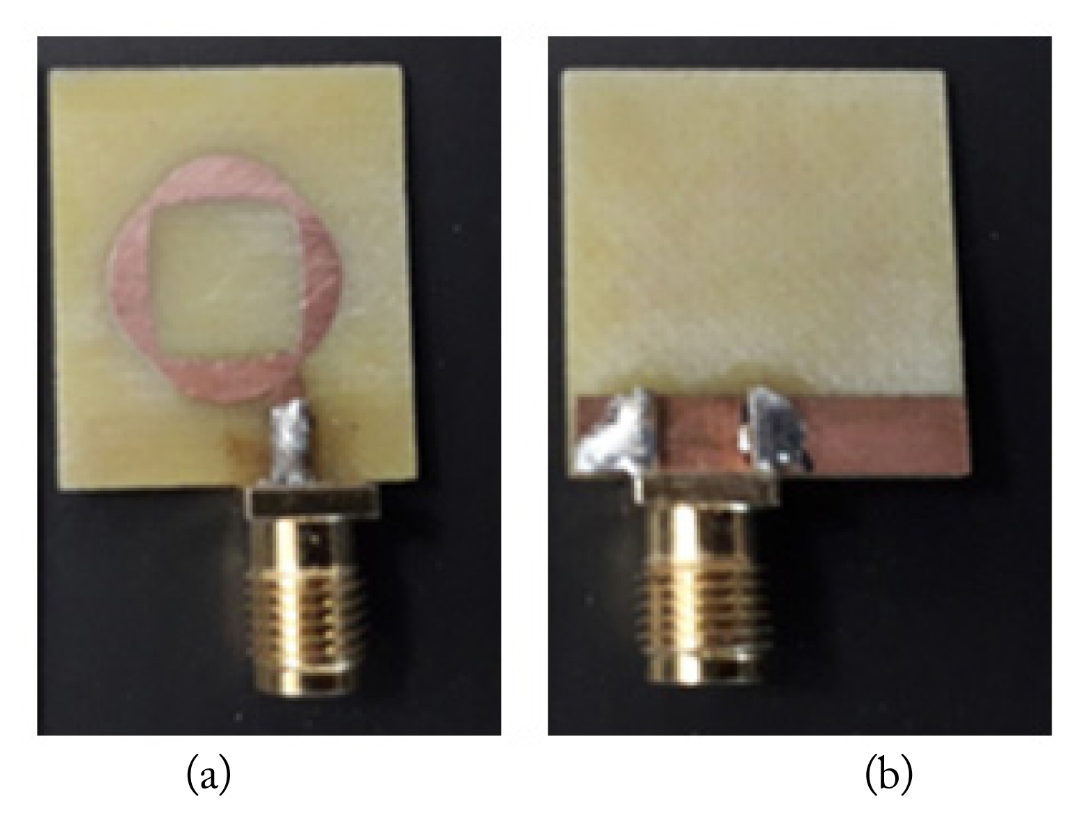
III. CMA of the Antenna Structure
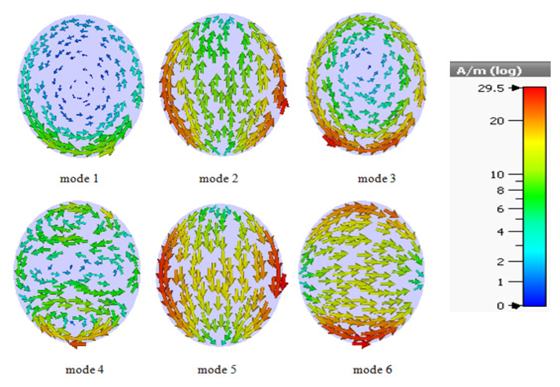
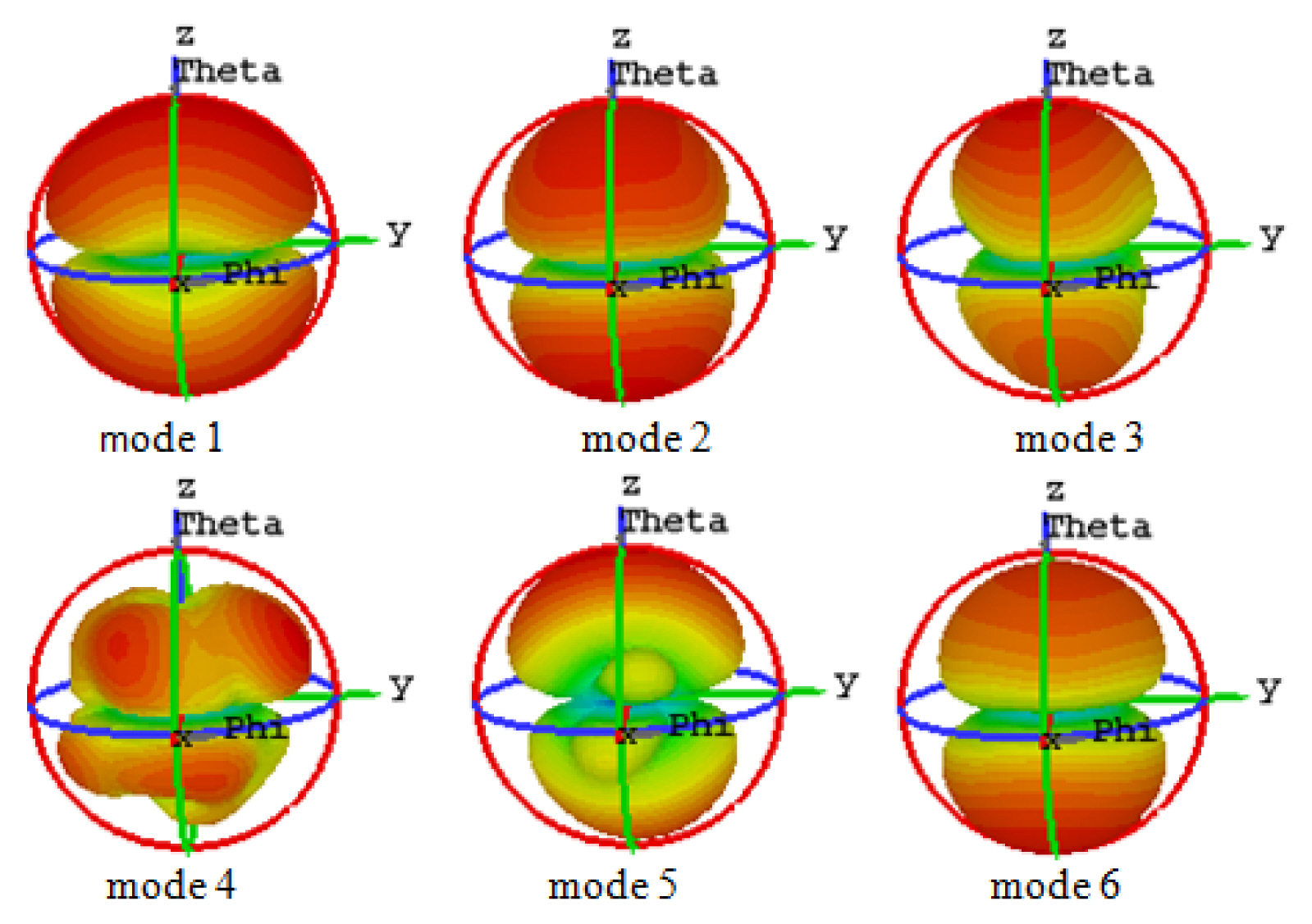
Mode 1 consists of medium current density at the bottom of the ellipse contour.
Modes 2 and 5 have more current density on the left and right contours and less inside the ellipse. The surface current direction for mode 2 is vertical upward, while for mode 5, it is the opposite. The centers of the top and bottom edges have null currents.
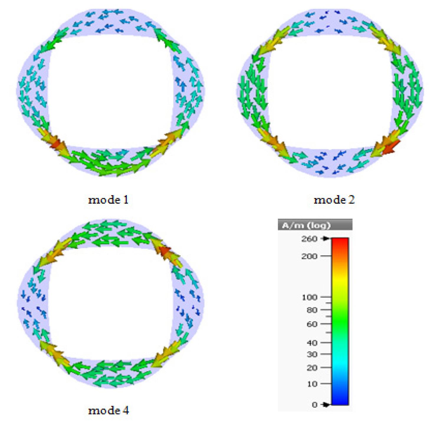
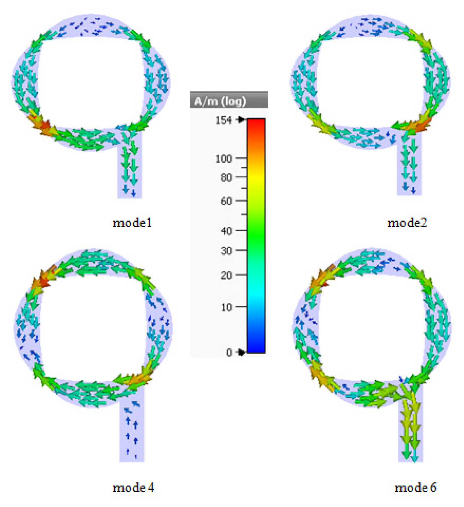
Modes 3 and 4 form the current loops, indicating that these modes are not involved in radiation.
Mode 6 has more current density on the top and bottom contour and less inside the ellipse. The surface current direction for mode 2 is horizontal. There are null currents at the centers of the left and right edges.
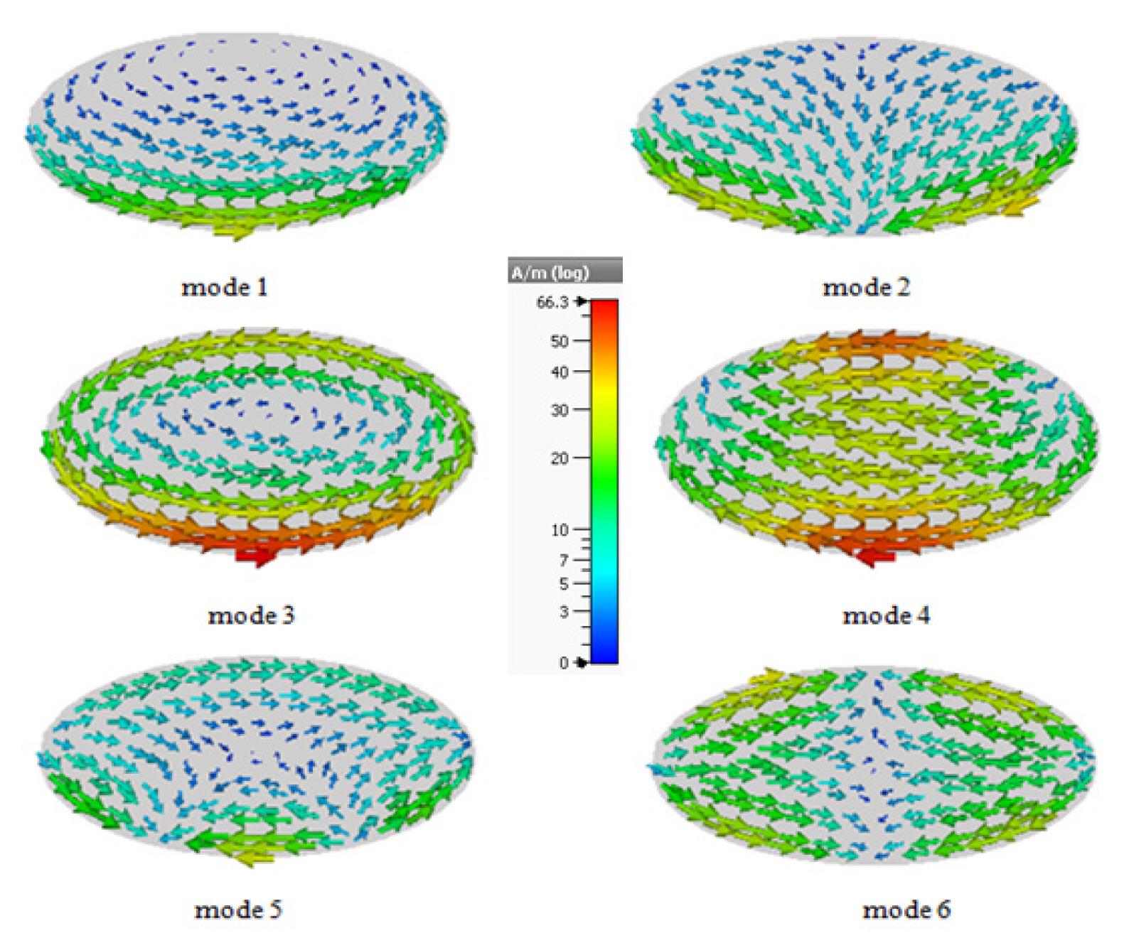
Mode 1 consists of medium current density at the lower edge of the ellipse contour, which corresponds to that of mode 1 in antenna-1, and nulls appear in the upper area.
Mode 2 has a current density at the bottom of the ellipse and flows in the opposite direction to the null current.
Mode 3 forms the current loop and indicates that this mode is not involved in the radiation.
Mode 4 has a current distribution over the entire area of the ellipse in the horizontal direction. Null currents are present in the upper left and right angles.
In mode 5, null is in the middle of the ellipse and medium current is present at the lower center.
In mode 6, the current flow along the x-axis is split about null in the middle of the y-axis in the opposite direction.
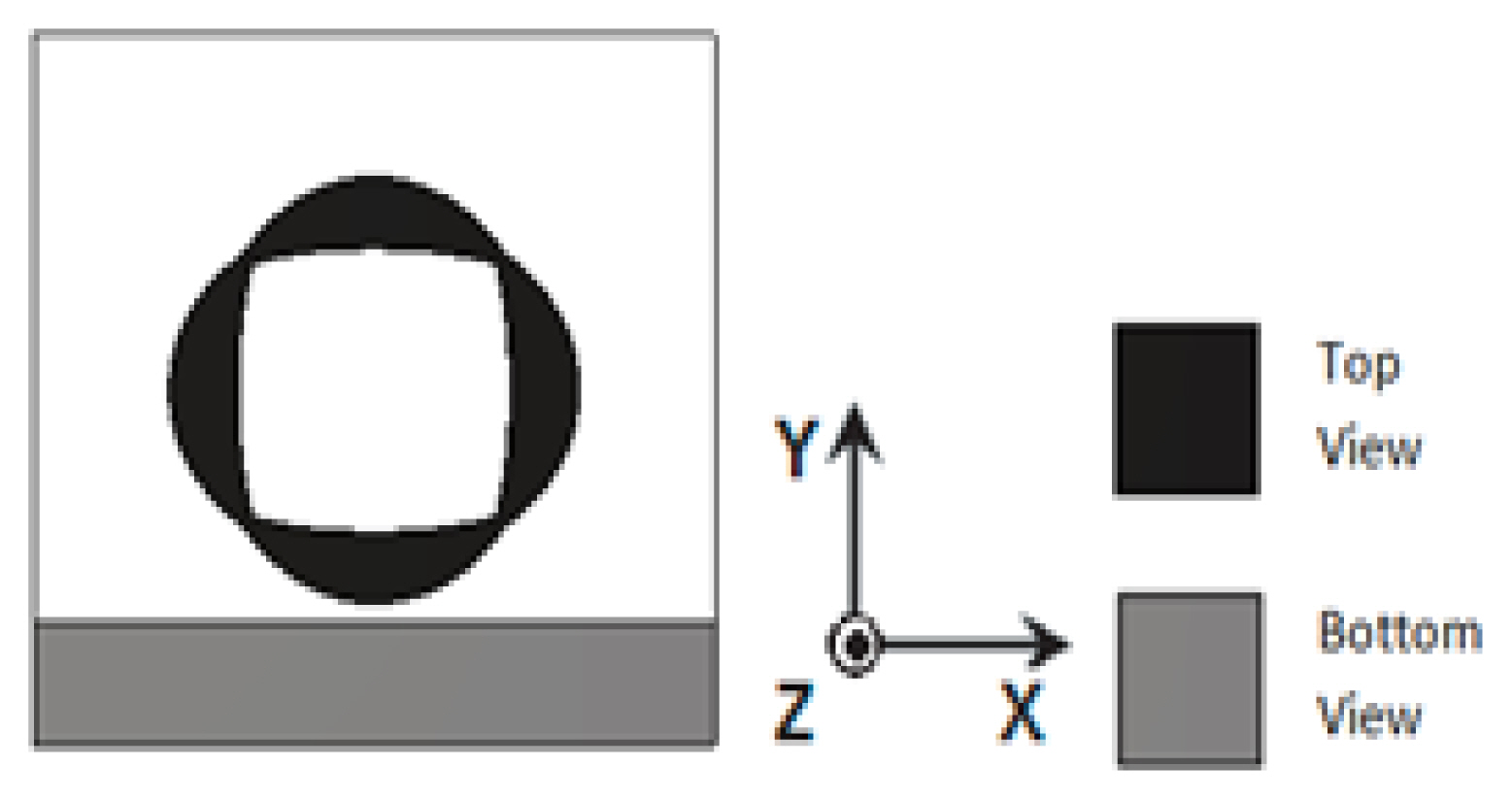
At the top left corner: the current flow of the three modes 1, 2, and 4 are in one direction.
At the top right corner: the current flow of modes 1 and 4 is in the same direction, but for mode 2, it is the opposite.
At the bottom left corner: the current directions of modes 1 and 2 are the same, but for mode 4, it is the opposite.
At the bottom right corner: the current directions of modes 2 and 4 are the same, but for mode 1, it is the opposite.