 |
 |
- Search
| J. Electromagn. Eng. Sci > Volume 21(4); 2021 > Article |
|
Abstract
Micro-Doppler signatures from the rotating propellers of a drone can be utilized to distinguish the drone from clutter or airborne organisms with similar radar cross section (RCS) levels, such as birds and bats. To obtain the micro-Doppler signatures of a drone, calculation or measurement of the electric field scattered from the rotating propellers is essential. In this paper, using the relative angle concept and far-field approximation, we propose a way to rapidly estimate the dynamic RCS of a drone with several propellers according to its movement. In addition, based on the fact that the shape of the propeller does not change even if it rotates, we construct an impedance matrix only once and apply the matrix to the method of moments instead of the iterative process of calculating the impedance matrix and inverse matrix for each rotation angle of the propeller. Finally, by using the Fourier transform of the results from the proposed method, the rotation frequencies of the propellers according to the movement of the drone can be obtained.
Recently, the use of drones has been increasing due to their drop in price and miniaturization. At the same time, drones can be abused, leading to issues like privacy violations. Moreover, there is the risk of collision, and they could also be used to transport illegal materials. However, conventional security systems are generally vulnerable to undetected small targets in the air; hence, interest in drone detection technology has increased.
Radar is an appropriate technology for detecting or tracking a target using its radar cross section (RCS). Therefore, early studies on drone detection mainly focused on estimating or measuring the RCS level of drones as well as airborne organisms that have an RCS level similar to that of drones [1]. Despite the existence of many such studies, the RCS level-based method still has difficulties in distinguishing drones from airborne organisms [2]. To solve this problem, methods based on the signature extracted from the RCS of a target rather than the simple RCS level have been studied [3ŌĆō13]. Inverse synthetic aperture radar (ISAR) images of small drones were investigated in [4]. Two-and three-dimensional ISAR images of drones are also used to classify drones. On the other hand, the micro-Doppler signatures induced by the flapping of various birdsŌĆÖ wings have been also investigated [5, 6]. Additionally, in [7ŌĆō10], the authors showed the difference between the micro-Doppler signatures of flapping bird wings and rotating drone propellers.
To obtain these micro-Doppler signatures for the detection and tracking of a drone, the measurement or estimation of electric fields scattered from the droneŌĆÖs propellers with respect to time is essential. Early studies mostly used the measured dynamic RCSŌĆöthe squared magnitude of the scattered field with respect to timeŌĆöbecause the estimation of the dynamic RCS from rotating propellers requires a large amount of computation time and resources. The measured dynamic RCS is realistic, but it is difficult to measure RCSs according to various drone situations. For this reason, the dynamic RCSs of drones have been generally only measured from hovering drones remaining in the same position. However, in [10], the authors showed that the dynamic RCSs of drones at aspect angles of 0┬░ and 90┬░ are considerably differentŌĆöthat is, the dynamic RCS of a drone is greatly affected by the observation angle. However, it is not easy to measure the dynamic RCS of a drone in the air from various angles.
In conventional commercial electromagnetic (EM) tools, the method of moments (MoM) solver generally performs a series of procedures, specifically mesh generation, construction of the impedance and admittance matrices, and calculation of the scattered field and RCS of a target. For the dynamic RCS of the rotating propellers of a drone, it is assumed that the quasi-static mode is established on a frame-by-frame basis with sampling intervals instead of a time-continuous model [11]. Therefore, MoM solvers repeatedly perform identical procedures for each frame. A substantial amount of time is needed to estimate the dynamic RCS of rotating propellers. Even though the propellers rotate, the shape of the propellers does not change; only the incident and scattered angles change. Therefore, using the relative angle between a rotating propeller and the incident field, mesh generation can be done just once along with the construction of the impedance and admittance matrices. Moreover, if the characteristics of the fields scattered from two types of drone propellersŌĆöclockwise (CW) and counter-clockwise (CCW) propellersŌĆöand far-field approximation are used, the fields scattered from all of the propellers can be synthesized with the scattered field of a single rotating propeller. This can result in a dramatic reduction in the calculation time.
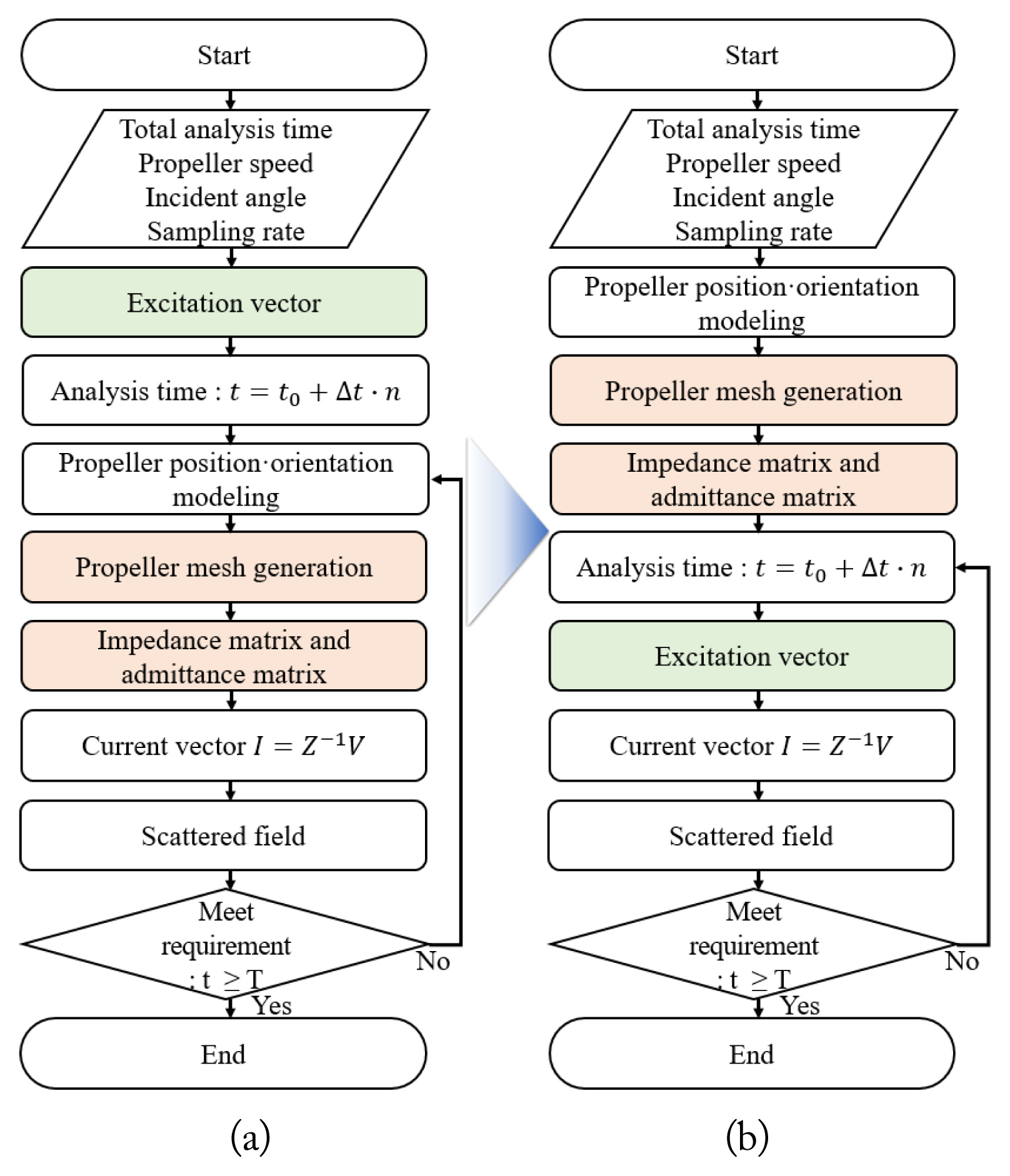
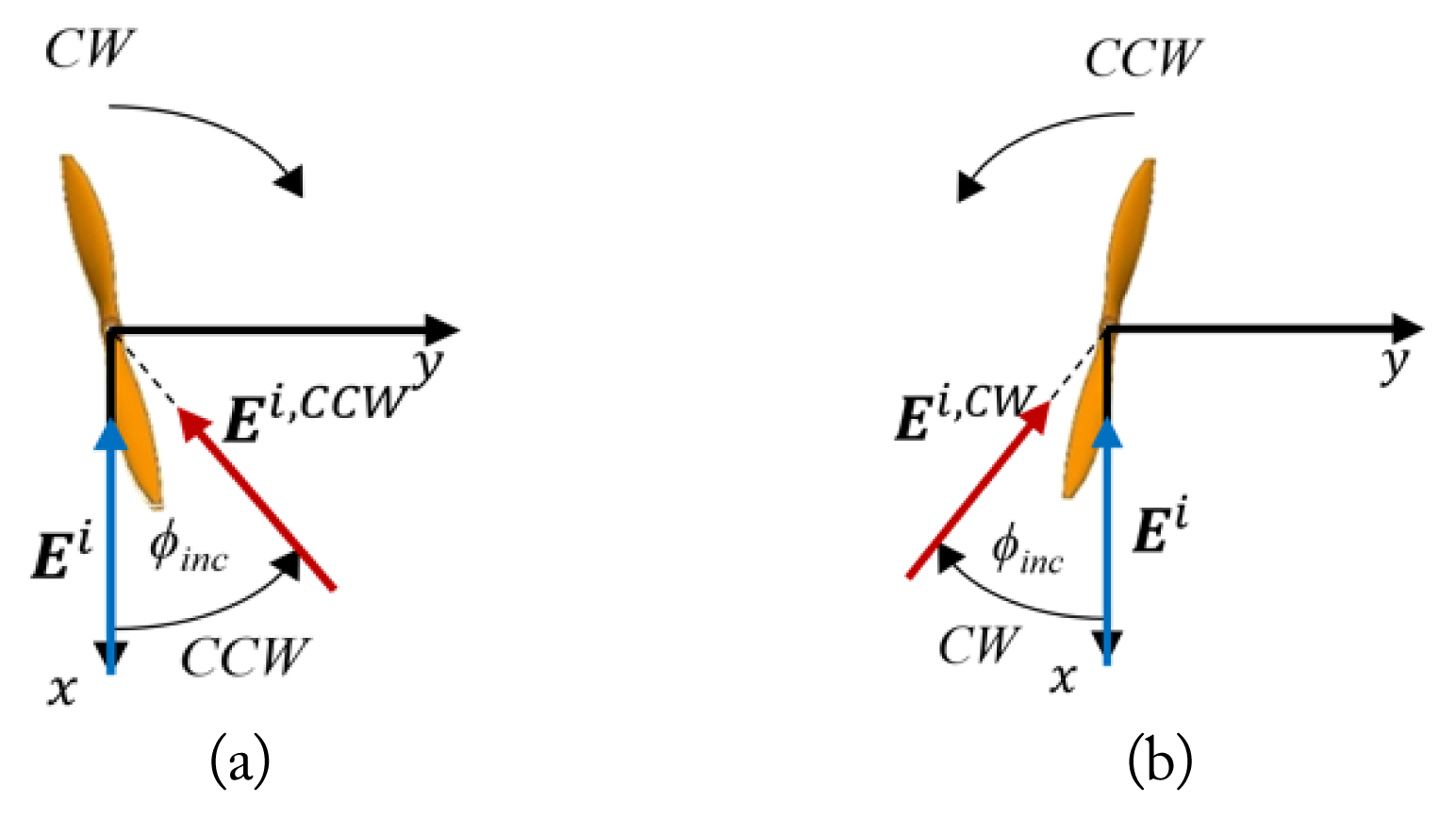
To calculate the electric field scattered from a single rotating propeller, MoM solvers in commercial EM tools perform a series of procedures sequentially, as shown in Fig. 1(a). The most time-consuming components of these MoM procedures are filling the impedance matrix and then converting it into an admittance matrix. It is well known that the impedance matrix in the MoM is constructed from the interaction among the mesh elements of a scatterer. Therefore, if the mesh is maintained while the scatterer is rotated, the impedance matrix does not change. That is, the mesh and the impedance matrix generated only once can be used continuously for a rotating propeller. As shown in Fig. 1(b), we reversely rotate the incident angle of the incident field in the rotation direction of the propeller instead of rotating the propeller, and its effect reflects on the excitation vector. Consequently, the current on the elements and the scattered field can obtained.
The electric field scattered from a propeller rotating clockwise, as shown in Fig. 2(a), can be expressed as
where SCW(t) and Ei are the scattering matrix of the CW rotating propeller and the incident electric field, respectively. Instead of rotating the propeller, if the incident azimuth angle, Žåinc, is rotated in the direction opposite to the rotation direction of the propeller, thus keeping the incident elevation angle, ╬Ėinc, fixed, the same scattered field as Eq. (1) can be obtained by
On the other hand, drones commonly consist of two types of propellers, namely, mirror-image symmetric CW and CCW propellers, as shown in Fig. 2. CW and CCW propellers rotate only clockwise and counter-clockwise, respectively. Because of their mirror-image symmetric characteristics, the co-polarized components of the electric fields scattered from CW and CCW propellers are the same, and the cross-polarized components have a phase difference of 180┬░. Therefore, the scattering matrices of the two types of propellers have the following relationship:
From Eq. (3), the electric field scattered from one type of propeller can be easily obtained from the electric field scattered from the other type without additional calculations.
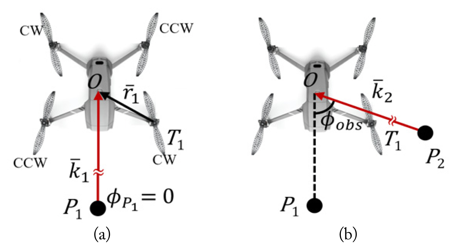
The geometry of a radar and a drone with 4 propellers is presented in Fig. 3(a). Let us assume that the origin, O, of the reference coordinate is the center of the drone, and the nth propeller and the radar are located at Tn and P1, respectively. If the radar, which faces the head of the drone, is far from the drone, then the backscattered field at the far-field can be approximated as
where
E T n s P 1 O ¯
Because a radar can be oriented in any direction, the RCS estimation of multiple propellers for the arbitrary azimuth angle is needed. Let us assume that the observation point is changed from P1 to P2 by changing only the azimuth angle from ŽåP1 to ŽåP2 while maintaining the elevation angle, ╬ĖP1. The incident and scattered angles is included in
E T n s ŌĆē ( t ; ╬Ė P 1 , Žå P 1 ) E T n s E T n s ŌĆē ( ╬Ė P 1 , Žå P 1 )
where Žåobs is the angle between
O P 2 ¯
The proposed method is implemented based on the MoM with a Rao-Wilton-Glisson (RWG) basis function using the electric field integral equation (EFIE). Since only the impedance matrix for a single propeller of the drone is used in our simulation, the calculation of the admittance matrix, which is an inverse matrix of the impedance matrix, is not time-consuming. Therefore, the admittance matrix was calculated simply using Gauss elimination rather than iterative methods, such as the conjugate gradient algorithm, the biconjugate gradient algorithm, and the generalized minimal residual method.
To verify the proposed method, the monostatic dynamic RCSs of rotating propellers were calculated and compared with the results obtained from a commercial EM tool. First, the radar operating frequency and pulse repetition frequency were set to 9.65 GHz and 20 kHz, respectively, in reference to existing radar specifications [12ŌĆō14]. Next, we choose DJIŌĆÖs Mavic2 [15], which is one of the most popular drones, as the simulation drone model. Since the micro-Doppler is mainly generated by rotating the propellers, we used a computer-aided design (CAD) model of propellers alone without the main body in the simulation. Each propeller was 20.32 cm long (which results in about 6.5╬╗ at 9.65 GHz) and was made of carbon fiber. Because the dynamic RCSs of propellers with carbon fiber and a perfect electric conductor (PEC) are very similar in terms of RCS level and patterns [16, 17], the material of the propellers was simply assumed to be the PEC.
The electric fields scattered from a single propeller rotating once a second were calculated at 0.1┬░ intervals for one second. The backscattered fields with respect to the transmitting and receiving polarizations are shown in Figs. 5 and 6. In the case of co-polarization (╬Ė ŌłÆ ╬Ė and Žå ŌłÆ Žå polarizations), the backscattered fields of the CW and CCW propellers are identical, while the fields of with cross-polarization (╬Ė ŌłÆ Žå and Žå ŌłÆ ╬Ė polarizations) are inverse of each other because of their mirror-symmetric shape and rotation in opposite directions. Their polarimetric characteristics can be used to derive the backscattered field from the other propellers by simply calculating the backscattered field of only one propeller. Therefore, with more propellers, the time for calculating the backscattered field can be reduced.
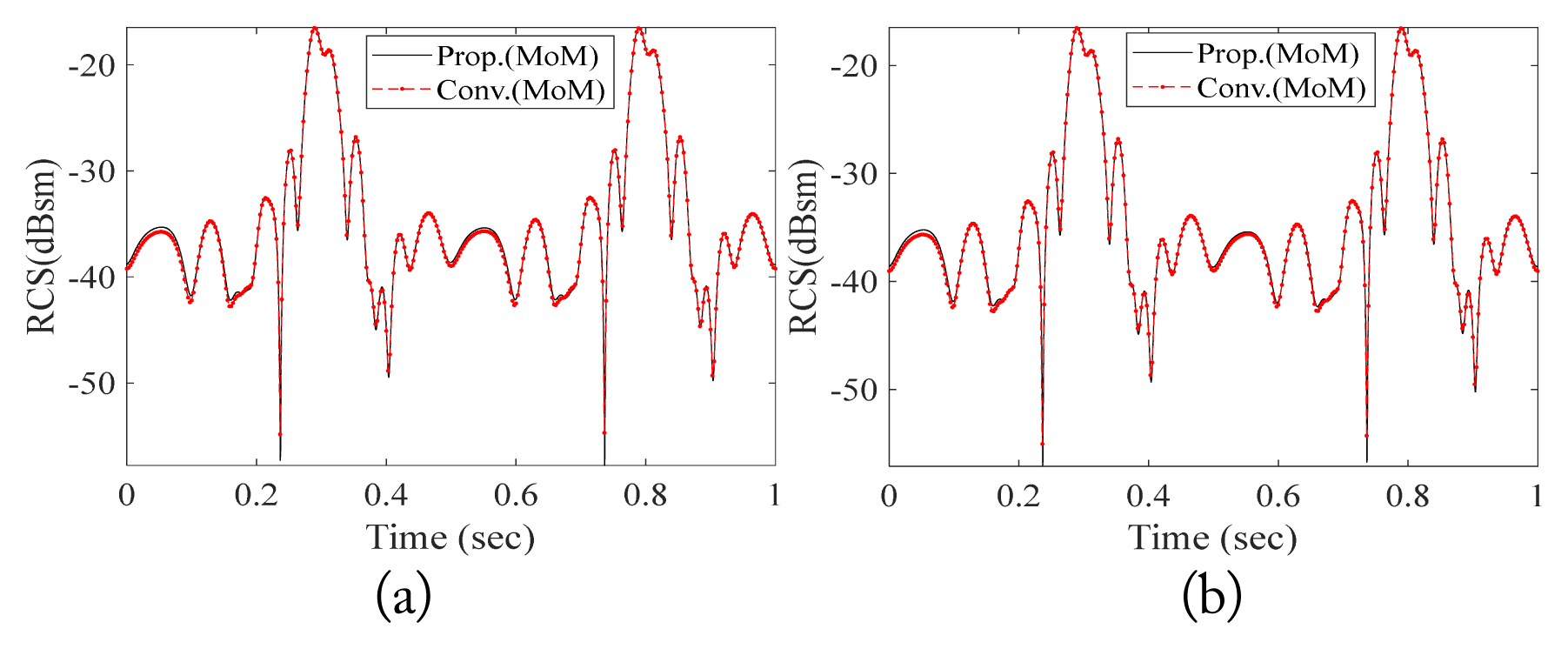
Fig. 7 shows the dynamic RCSs of the two types of propellers. The proposed method was implemented using MATLAB, and the MoM solver of AltairŌĆÖs FEKO was used as the conventional method. We performed all the simulations using a PC with Intel Core i7-8700 at 3.20 GHz and 64 GB RAM. There was little deviation in the results. As expected, since the proposed method makes the admittance matrix only one time during the observation time (or dwell time), the proposed method considerably reduces the calculation time of a single propeller in comparison with the conventional method, as summarized in Table 1.
We also simulated a case in which the radar was located in front of a drone with four propellers rotating at 156.6 Hz, as shown in Fig. 3(a), and the elevation and azimuth angles of the incident field were 45┬░ and 0┬░, respectively. The dynamic RCSs and backscattered spectrum were calculated during one rotation period. Fig. 8(a) shows the dynamic RCS of the ascending drone. The proposed method was implemented with the procedure shown in Fig. 1(b), while the conventional method, FEKOŌĆÖs MoM solver, was performed at every time step using the procedure shown in Fig. 1(a). As a result, it took a large amount of time to estimate the dynamic RCS of the multiple propellers. Therefore, the conventional method for estimating the dynamic RCS of multiple propellers was implemented using FEKOŌĆÖs multilevel fast multipole method (MLFMM) solver. Fig. 9 shows the frequency response with the application of fast Fourier transform to the dynamic RCS. The frequency of the first peak is 313.2 Hz, which is twice as high as the rotation frequency because the two scattering points at both ends of the propeller rotate.
Fig. 8(b) shows the dynamic RCS when the radar is looking at the aspect of the drone at ŽåP2 = 70┬░. Compared to the front-looking case of Fig. 8(a), the dynamic RCS pattern is considerably changed. However, the back-scattered spectrum is similar. The first peak frequency is also 313.3 Hz, as shown in Fig. 9(b), which means the rotation frequency can be successfully obtained from the frequency-domain of the dynamic RCS.
In considering a drone moving forward with the two front propellers rotating more slowly than the two back propellers, we set the rotation frequencies of the front and back propellers to 125.3 Hz and 156.6 Hz, respectively. The azimuth and elevation angles between the head of the drone and the radar were 0┬░ and 45┬░, respectively. The dynamic RCS of the advancing drone is shown in Fig. 8(c), and the frequencies of the first and second peaks in Fig. 9(c) are 250.6 Hz and 313.3 Hz, respectively, which are twice as high as the rotation frequencies. However, there is some discrepancy between the proposed and conventional methods in Fig. 9(c). This discrepancy seems to be due to the assumption that there is no coupling among the propellers for high-speed computation. For the quantitative analysis of the discrepancy, the normalized root-mean-square deviation (NRMSD) between the results of the proposed and conventional methods are summarized in Table 2. The NRMSDs between the results of the proposed method and conventional method are summarized in Table 2. Specifically, the NRMSDs are less than 2%, and the proposed method accurately estimates the dynamic RCSs of the four propellers. Above all, the proposed method considerably reduces the calculation time of the dynamic RCS 8 to 10 times compared with the conventional method, as seen in Table 3.
We introduced a MoM-based method to quickly estimate the dynamic RCSs of rotating objects. Conventional MoM solvers used in commercial EM tools repeatably construct the impedance matrix and its inverse matrix for a rotating object at every time interval, whereas the proposed method constructs the impedance matrix only once by rotating the incident angle instead of rotating the object. This core principle is applicable not only to drones but also to various objects with propellers [18, 19]. In addition, a multi-propeller dynamic RCS is synthesized via far-field approximation assuming that there is no coupling between the propellers and using the characteristics of two mirror-symmetric types of propellers used in drones. The proposed method can rapidly calculate a droneŌĆÖs scattered fields from various angles, especially the aspect. From the estimated dynamic RCS, the rotation frequency of the propeller could be accurately obtained. Therefore, the proposed method can be effectively used to obtain the micro-Doppler of drones by estimating the dynamic RCS of various drone movements as well as various types of drones, such as drones with four or more propellers and drones with different sizes of propellers, to estimate the dynamic RCS of drone propellers with various materials in the future.
Acknowledgments
This work was supported by the Korea Foundation for the Advancement of Science & Creativity (KOFAC) funded by the Korean Government (MOE) and supported by the Basic Science Research Program through the National Research Foundation of Korea (NRF) funded by the Ministry of Education (No. 2021R1I1A304405).
Fig.┬Ā4
Initial directions of propellers due to changed observation point: (a) when the change angle is applied only to the wave vector and (b) when it is applied to both the scattered field and wave vector.
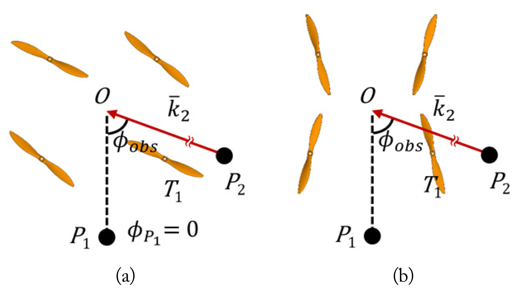
Fig.┬Ā5
Comparison of the real value of the electric field of CW and CCW propellers. (a) ╬Ė-╬Ė pol. (b) ╬Ė-Žå pol. (c) Žå-Žå pol. (d) Žå-╬Ė pol.
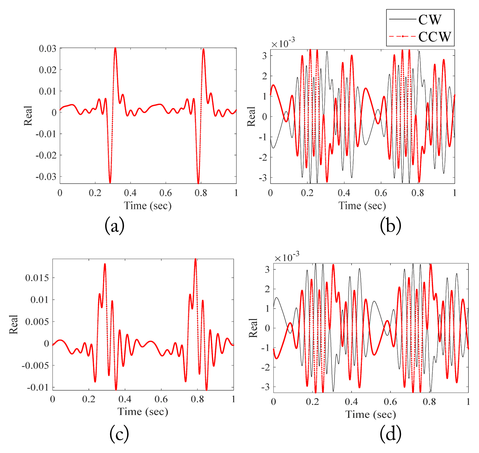
Fig.┬Ā6
Comparison of the imaginary value of the electric field of the CW and CCW propellers. (a) ╬Ė-╬Ė pol. (b) ╬Ė-Žå pol. (c) Žå-Žå pol. (d) Žå-╬Ė pol.
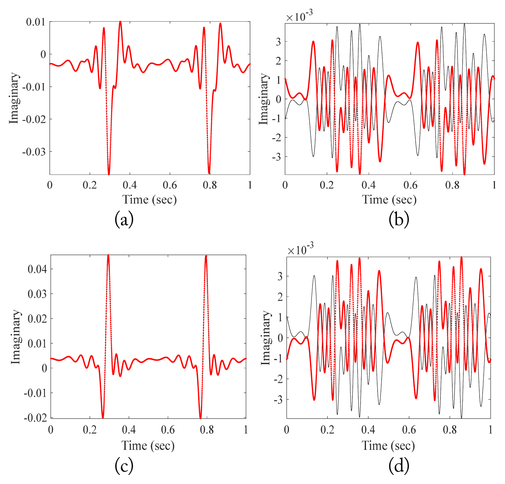
Fig.┬Ā8
Dynamics RCS╬Ė╬Ė calculated by using the proposed and conventional methods when the drone is in (a) ascent, (b) ascent (aspect), and (c) advance.

Fig.┬Ā9
Backscattered spectrum calculated by using the proposed and conventional methods when the drone is in (a) ascent, (b) ascent (aspect), and (c) advance.

Table┬Ā1
Calculation time for rotating propeller
| Time (hh:mm:ss) | |
|---|---|
| Conventional | 20:01:12 |
| Proposed | 00:07:40 |
Table┬Ā2
NRMSDs of the difference between the results of the MoM and MLFMM from Fig. 8
| Movement | NRMSD (%) |
|---|---|
| Ascent | 0.50 |
| Ascent (aspect) | 0.79 |
| Advance | 1.03 |
References
1. D Mirkovic, PM Stepanian, JF Kelly, and PB Chilson, "Electromagnetic model reliably predicts radar scattering characteristics of airborne organisms," Scientific Reports, vol. 6, article no. 35637, 2016.
https://doi.org/10.1038/srep35637


2. S Rahman and DA Robertson, "In-flight RCS measurements of drones and birds at K-band and W-band," IET Radar, Sonar & Navigation, vol. 13, no. 2, pp. 300ŌĆō309, 2019.

3. JS Patel, F Fioranelli, and D Anderson, "Review of radar classification and RCS characterisation techniques for small UAVs or drones," IET Radar, Sonar & Navigation, vol. 12, no. 9, pp. 911ŌĆō919, 2018.

4. M Pieraccini, L Miccinesi, and N Rojhani, "RCS measurements and ISAR images of small UAVs," IEEE Aerospace and Electronic Systems Magazine, vol. 32, no. 9, pp. 28ŌĆō32, 2017.

5. B Torvik, KE Olsen, and HD Griffiths, "X-band measurements of radar signatures of large sea birds," In: Proceedings of 2014 International Radar Conference; Lille, France. 2014, pp 1ŌĆō6.

6. M Ritchie, F Fioranelli, and H Griffiths, "Monostatic and bistatic radar measurements of birds and micro-drone," In: Proceedings of 2016 IEEE Radar Conference (RadarConf); Philadelphia, PA. 2016, pp 1ŌĆō5.

7. T Li, B Wen, Y Tian, Z Li, and S Wang, "Numerical simulation and experimental analysis of small drone rotor blade polarimetry based on RCS and micro-Doppler signature," IEEE Antennas and Wireless Propagation Letters, vol. 18, no. 1, pp. 187ŌĆō191, 2019.

8. MA Govoni, "Micro-Doppler signal decomposition of small commercial drones," In: Proceedings of 2017 IEEE Radar Conference (RadarConf); Seattle, WA. 2017, pp 425ŌĆō429.

9. S Rahman and DA Robertson, "Radar micro-Doppler signatures of drones and birds at K-band and W-band," Scientific Reports, vol. 8, article no 17396, 2018.
https://doi.org/10.1038/s41598-018-35880-9

10. BK Kim, HS Kang, and SO Park, "Experimental analysis of small drone polarimetry based on micro-Doppler signature," IEEE Geoscience and Remote Sensing Letters, vol. 14, no. 10, pp. 1670ŌĆō1674, 2017.

11. P Pouliguen, L Lucas, F Muller, S Quete, and C Terret, "Calculation and analysis of electromagnetic scattering by helicopter rotating blades," IEEE Transactions on Antennas and Propagation, vol. 50, no. 10, pp. 1396ŌĆō1408, 2002.

12. VK Kothapudi and V Kumar, "Compact 1├Ś2 and 2├Ś2 dual polarized series-fed antenna array for X-band airborne synthetic aperture radar applications," Journal of Electromagnetic Engineering and Science, vol. 18, no. 2, pp. 117ŌĆō128, 2018.

13. L Lehmann and J Dall, "Simulation-based approach to classification of airborne drones," In: Proceedings of 2020 IEEE Radar Conference (RadarConf20); Florence, Italy. 2020, pp 1ŌĆō6.

14. PJ Speirs, A Schroder, M Renker, P Wellig, and A Murk, "Comparisons between simulated and measured X-band signatures of quad-, hexa-and octocopters," In: Proceedings of 2018 15th European Radar Conference (EuRAD); Madrid, Spain. 2018, pp 325ŌĆō328.

15. Specification for the DJI Mavic-2. [Online]. Available:https://www.dji.com/kr/mavic-2/info#specs
16. A Schroder, M Renker, U Aulenbacher, A Murk, U Boniger, R Oechslin, and P Wellig, "Numerical and experimental radar cross section analysis of the quadrocopter DJI Phantom 2," In: Proceedings of 2015 IEEE Radar Conference; Johannesburg, South Africa. 2015, pp 463ŌĆō468.

17. M Ritchie, F Fioranelli, H Griffiths, and B Torvik, "Micro-drone RCS analysis," In: Proceedings of 2015 IEEE Radar Conference; Johannesburg, South Africa. 2015, pp 452ŌĆō456.

18. SH Choi, DW Seo, and NH Myung, "Scattering analysis of open-ended cavity with inner object," Journal of Electromagnetic Waves and Applications, vol. 21, no. 12, pp. 1689ŌĆō1702, 2007.

19. WY Yang, DJ Yun, and DW Seo, "Novel automatic algorithm for estimating the jet engine blade number of insufficient JEM signals," Journal of Electromagnetic Engineering and Science.
20. SN Makarov, Antenna and EM Modeling with MATLAB. New York, NY: Wiley-Interscience, 2002.
Biography

Dong-Yeob Lee received a B.S degree in radio communication engineering from Korea Maritime and Ocean University, Busan, South Korea in 2021. He is currently working toward his M.S. degree at the same university. His research interests include numerical techniques in areas of the electromagnetics and radar cross-section analysis.
Biography

Jae-In Lee received a B.S. degree in electrical engineering from Kyungpook National University, Daegu, South Korea, in 2012 and Ph.D. degrees in electrical engineering from Korea Advanced Institute of Science and Technology (KAIST), Daejeon, South Korea, in 2019. He is currently a post-doctoral researcher associate with the Interdisciplinary Major of Maritime AI Convergence, Korea Maritime and Ocean University (KMOU), Busan, South Korea. His research interests include numerical techniques in the areas of electromagnetics, radar cross-section analysis, and inverse synthetic aperture radar imaging.
Biography

Dong-Wook Seo received the B.S. degree in electrical engineering from Kyungpook National University, Daegu, South Korea, in 2003, and M.S. and Ph.D. degrees in electrical engineering from Korea Advanced Institute of Science and Technology (KAIST), Daejeon, South Korea, in 2005 and 2011, respectively. He was a senior researcher for the Defense Agency for Technology and Quality (DTaQ), Daegu, from 2011 to 2012. From 2012 to 2017, he was a senior researcher with the Electronics and Telecommunications Research Institute (ETRI), Daegu. Since September 2017, he has been a faculty member of the Department of Radio Communication Engineering, Korea Maritime and Ocean University (KMOU), Busan, South Korea, where he is currently an associate professor. His current research interests include numerical techniques in the areas of electromagnetics, radar cross-section analysis, wireless power transfer, and radar systems.
- TOOLS
- Related articles in JEES


