I. Introduction
Optoelectronic oscillators (OEOs) have attracted significant attention owing to their ultra-low phase noise performance in generating micro-/millimeter wave signals. The OEO signal can be used in various applications, such as next-generation wireless communications, remote sensing, and frequency standards [1]. The low loss and long delay of optical fiber in the OEO loop can provide superior phase noise performance compared with the other types of electrical oscillators. Furthermore, high frequency generation can be achieved owing to the high frequency nature of optical sources [2].
Despite the low noise and high frequency performances, spurious tones closely spaced near the target oscillation signal hinder the application of OEO in real-world situations. They are located at intervals of hundreds of kHz around the oscillation signal for a several kilometer fiber loop. They cannot be easily filtered out by an electrical bandpass filter because the passband is too narrow. Therefore, the spurious-tone suppression ratio (SSR) is a major factor in evaluating OEO performance and ensuring a single-frequency operation at a target frequency. Multi-loop OEO (MOEO) has been experimentally reported and successfully exhibited SSR improvement [3]. Interference between the signals in the MOEO loop with different delays suppresses the spurious tones through the Vernier effect [4]. The accurate extraction of the loop parameters of MOEO, which are length and power ratios between multiple loops, is critical for achieving high SSR and low phase noise simultaneously. The open-loop response has been a typical analysis method for predicting OEO performances based on amplitude and phase responses [5]. Although open-loop response analysis is simple and intuitive, the OEO signal magnitude finally generated cannot be calculated by the method because the feedback effect is not considered in the analysis.
To overcome the limitations of open-loop analysis and to extract the optimal parameters of the MOEO with increased SRR and high-phase noise performance, we propose a closed-loop analysis that involves the feedback effect of the MOEO. First, we derived the magnitude and phase response of the closed-loop MOEO. Second, we calculated the spectrum of all oscillation signals, including target and spurious signals, for various loop power ratios. Finally, we extracted an optimum power ratio to achieve SSR improvement with low phase noise. We successfully achieved a theoretical demonstration of a triple-loop OEO signal with an SSR of 86 dB and a phase noise of −115 dBc/Hz at 10 kHz offset.
II. Evaluation of Spurious-Tone Suppression based on Closed-Loop Analysis of MOEO
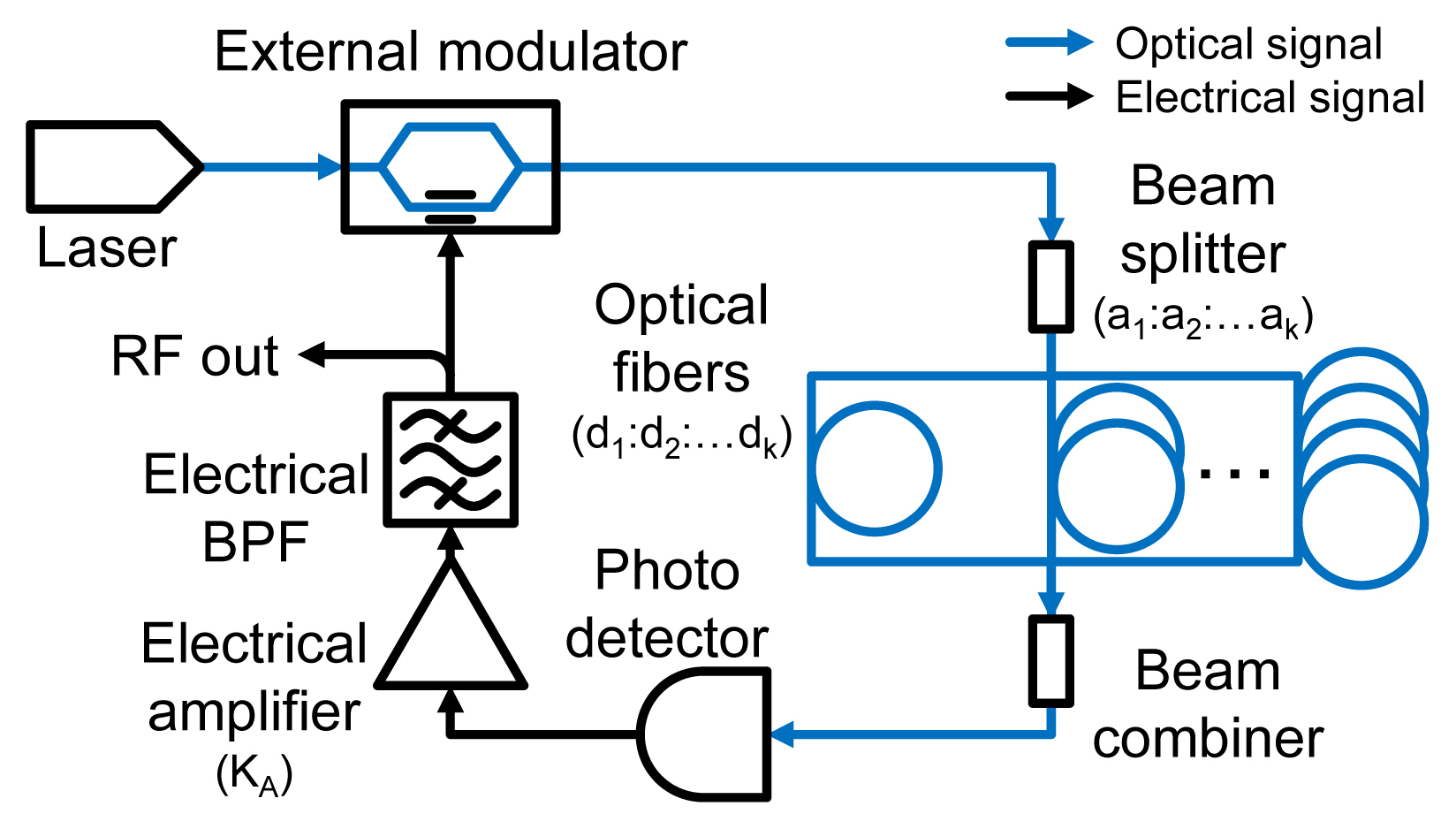
Fig. 1 shows the configuration of MOEO [3]. Blue and black solid lines represent the optical and electrical signal paths, respectively. The optical path consists of a laser, beam splitter, beam combiner, and optical fibers. The electrical path consists of an electrical bandpass filter and an amplifier. The optical and electrical paths are connected by a photodetector. The target output signal with micro-/millimeter-wave frequency is tapped in front of an external optical modulator. The modulator realizes the feedback loop through optical modulation. Oscillation signals can be achieved in the feedback loop when the loop gain approaches higher than unity and the phase change satisfies the in-phase condition through a single path. The Vernier effect uses the overlap responses of individual loops with different loop parameters. The effect was adjusted by controlling the loop parameters of power (a1:a2:a3) and length ratio (d1:d2:d3) for the triple loop in our calculation. By a long loop delay in the optical fiber combined with the adjustment of the loop parameters, a pure micro-/millimeter-wave oscillation signal with a high SSR and low-phase noise can be achieved. An open-loop response of MOEO is derived based on the configuration in Fig. 1 as follows:
where H0 is the comprehensive response of non-dominant devices in spurious-tone analysis, including an external modulator, electrical bandpass filter, and photodetector. KA is the gain of the electrical amplifier, k is the number of multiple loops, m is the natural number, am is the loop power ratios of the beam splitter, ω is the angular frequency in the electrical domain, n is the refractive index of the fiber, c0 is the speed of light, and dm is the length of the fibers. The loop power ratios of the optical beam splitter is defined by the following:
The closed-loop response of feedback loop oscillators [6] can be expressed by the following:
where ρn is the noise floor. Since MOEO and feedback-loop oscillator exhibit the same operation principle [1], the closed-loop response of MOEOs can be derived as Eq. (3) based on noise floor calculation and the open-loop response of MOEOs of Eq. (1). We set the calculation parameters as follows: H0 is unity, KA is 1.5, k is 3, n is 1.5, c0 is 3 × 10⁸ m/s, and ρn is −120 dBm/Hz. The loop length ratio is fixed at d1:d2:d3 = 1:5.5:10 km because the loop power ratio is an easier control parameter than the length ratio in real application. We simulated the closed-loop response as a function of angular frequency ω by adjusting the loop power ratios using MATLAB.
Fig. 2 shows the calculated SSR for various loop power ratios with a fixed length ratio of 1:5.5:10 for the triple-loop OEO case. Note that the number of loops and loop parameters may vary depending on the configuration. The closed-loop responses are calculated by controlling the power ratio with Eqs. (1)–(3). The area shaped as a right triangle occupying half of the left part of the plot represents the calculated SSR for various values of a1 and a2 (a3 = 1 − (a1 + a2)). The SSR in the gray region ranges from 0 to 10 dB, exhibiting the high-power oscillation of the spurious modes. The SSR in color grade abruptly increases compared with the gray region and exhibits an SSR of >86 dB owing to the Vernier effect. We also calculated the phase noise (not shown in the figure) for the various power ratios to achieve high SSR and low phase noise simultaneously. For example, the MOEO exhibits a high SSR of 86 dB and a low phase noise performances of −115 dBc/Hz at 10 kHz offset for the loop power ratio of 0.332:0.131:0.537. The target frequency is set at 10 GHz. Since we could calculate the spectrum of all oscillation signals, including the target and spurious signals, we finally evaluated the phase noise performance. Fig. 3 shows the phase noise of the triple-loop OEO for the highest SSR case. The MOEO case exhibits a significant reduction of spurious tone (SSR of 86 dB at 20 kHz offset) and a slight increase in phase noise (2 dB at 10 kHz offset). It also exhibits an improved phase noise reduction (>6 dB at 10 kHz offset) compared with a short optical fiber (1 km).
III. Conclusion
We evaluated the SSR and phase noise performance of MOEO based on the closed-loop response. The oscillation signal spectrum, including a target and spurious tones, was calculated using closed-loop analysis. We accurately extracted the operation parameters of the MOEO using the analysis and achieved high SSR and low-phase noise simultaneously. The MOEO with accurate loop parameters can be applied to various applications, including wire/wireless optical communications, remote sensing, and frequency standards.