A Miniaturized Implantable Antenna for Wireless Power Transfer and Communication in Biomedical Applications
Article information
Abstract
A miniaturized, triple-band, implantable antenna for biomedical applications is presented in this paper. The proposed antenna with dimensions of 8.1 mm × 8.1 mm × 0.64 mm, combined with a shorting pin and a ground slot, operates at bands between 401–406 MHz for the medical implant communications service (MICS); 1,395–1,400 MHz and 1,427–1,432 MHz for the wireless medical telemetry service (WMTS); and 2,400–2,500 MHz for industrial, scientific, and medical (ISM) applications. The antenna is deployed simultaneously for data transmission and wireless power transfer (WPT) at the two frequencies of communications and the ISM band, respectively. The antenna achieves peak gain values of −35.7 dBi, −25.1 dBi, and −19.5 dBi with the impedance bandwidths of 10.1%, 15.5%, and 9.58% at 402 MHz, 1.4 GHz, and 2.45 GHz, respectively. The experiments in the muscle tissue were implemented to demonstrate the reliability of the proposed antenna. To ensure safety standards in the human body environment, the specific absorption rate (SAR) value is simulated and evaluated thoroughly.
I. Introduction
Wireless implanted medical devices (IMDs) have been used commonly in biomedical applications. They can assist in monitoring a patient’s temperature and blood pressure; as well as detecting interior bodily problems, such as rapid heartbeat, brain hemorrhage and transmitting signals to external monitoring or control equipment. The medical implant communication service (MICS) band at 401–406 MHz; and the wireless medical telemetry service (WMTS) band at 1,395–1,400 and 1,427–1,432 MHz have been accepted worldwide for transmitting data for implantable medical devices, due to these advantageous properties of the bands: good conductivity in the human body, a higher data rate, and a large communication range [1].
Currently, the integrated battery in IMDs has several drawbacks, such as limited lifetime, large size, and the incremental possibility of tissue inflammation [2]. To overcome this restriction, the wireless powering technique is used to minimize size and ensure energy-supplying continuity for the implanted receiver system [3, 4]. Furthermore, the industrial, scientific, and medical (ISM) band at 2.45 GHz has been chosen in recent studies for its wireless power transfer (WPT) capabilities [5, 6]. At a high frequency, losses in the human tissue increase, whereas at a lower frequency, the losses reduced easily transmit signals, but it requires a large antenna size. Additionally, there are challenges related to gain and bandwidth in the design of implantable antennas. To make reasonable solution, the MICS and WMTS bands are used for data transmission with an optimized bandwidth, while the ISM band is used to transfer power with high gain characteristics. Moreover, an implantable antenna of a small size can reduce the risk of infection and increase durability. Recently, the planar inverted–F antenna (PIFA) [7–9], the meander-line (ML) antenna [10], and the loop antenna [11] have been widely used for implantable devices. Because they operate at multiple bands, using the shorting pin, ground slot, or shunt capacitor can easily adjust to the desired resonant frequencies [12].
In this paper, a miniaturized implantable antenna is designed based on the new structure of an ML antenna combined with a shorting pin and the ground slot to operate at the MICS (402 MHz), WMTS (1.4 GHz), and ISM (2.45 GHz). The position of the shorting pin and feeding at the ML conductive are analyzed to ensure that the antenna can operate exactly at the triple bands. The proposed antenna is compact in size: 8.1 mm × 8.1 mm × 0.64 mm. It also simultaneously operates in two modes: data transmission at the MICS and WMTS bands for communication, and wireless power transfer at the ISM band, making it suitable for biomedical applications. The antenna is simulated and measured within the homogenous muscle tissue. Finally, the SAR value is simulated to verify the safety of the antenna in the human body.
II. Design of Implanted Antenna
1. Simulation Setup
The proposed antenna is simulated in a homogeneous muscle phantom, a single-layer tissue box with a dimensions of 100 mm × 100 mm × 50 mm. The properties of the muscle tissue are reported in [13], where the dielectric (ɛr) and conductivity (σ) are dependent on the frequency: ɛr =57.1 and σ=0.79 (S/m) at 402 MHz, ɛr =54.1 and σ=1.14 (S/m) at 1.4 GHz, and ɛr =52.7 and σ=1.74 (S/m) at 2.45 GHz. The implantation depth of the antenna is 5 mm below the surface of the muscle, as shown in Fig. 1(a). The ANSYS High-Frequency Structure Simulator (HFSS) is used to analyze the full-wave electromagnetic simulation of the antenna, and the specific absorption rate (SAR) value is calculated based on the human model.
2. Antenna Structure and Analysis Parameters
Fig. 1(b) shows the configuration of the proposed implanted antenna. The antenna consists of a substrate, superstrate, an ML conductive material, a shorting pin, and a ground plane. The Taconic RF-10 substrate (ɛr =10 and tanδ= 0.0035) is used for both the superstrate and the substrate with the same thickness of 0.64 mm and the dimensions of 8.1 mm × 8.1 mm. The superstrate acts as a separation layer between the ML conductive and the surrounding environment, reducing the amount of heat that reaches the muscle tissue. Additionally, the insulating material with a higher dielectric constant can produce a higher maximum power transfer efficiency value and increase the radiating electric field, as investigated in [14]. The ML conductive at the top of the substrate is connected to the ground plane at the bottom by a shorting pin with a diameter of 0.3 mm, and the geometry of the ML conductive is shown in Fig. 1(c). The antenna is excited by using a 50-Ω coaxial feeding port. Backward radiation from the implanted antenna harms the human body, and the ground plane reduces the effect of radiation on tissues. The final optimized dimensions of the proposed antenna are presented in Table 1.
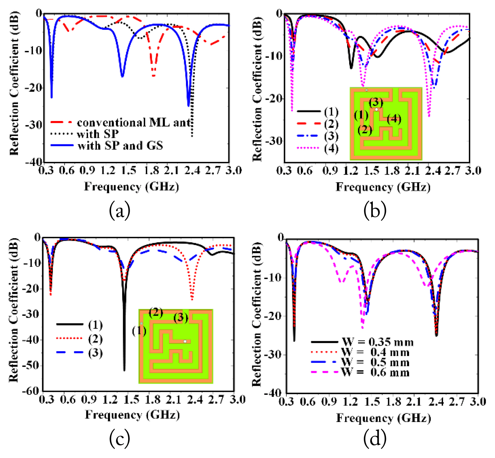
Fig. 2(a) shows the effect of the antenna’s reflection coefficient when utilizing the shorting pin and ground slot. The conventional ML antenna without both the shorting pin and the ground slot resonates at a single band of 1.9 GHz. The lower frequency band is shifted to 402 MHz by an insertion shorting pin, which is the prolongation of the current path from the ML conductive to the ground plane, increasing the electrical length of the antenna. The ML conductive is shorted at the end. Therefore, at this frequency, the ML conductive has the same current distribution as shown in Fig. 3(a). With the shorting pin, the antenna concurrently operates at the MICS and ISM bands. To generate one more resonant frequency, the impedance characteristic at the WMTS band can be compensated for by the ground slot. With the long distance between a slot with a shorting pin and a feeding as shown in Fig. 1(d), the ground slot can yield good impedance at 1.4 GHz and does not significantly affect other resonant frequencies.

Reflection coefficient of the antenna: (a) effect of the shorting pin (SP) and ground slot (GS), (b) change in the position of the SP, (c) change in the position of feeding, and (d) change the width of the ML conductive.

Distribution current at the resonant frequency on the ML conductive: (a) 402 MHz, (b) 1.4 GHz, and (c) 2.45 GHz.
The impedance characteristics are also affected by the position of the shorting pin. As mentioned before, the shorting pin directly influences the current path. Hence, all resonant frequencies are varied when the shorting pin on the ML conductive is moved, as shown in Fig. 2(b). Meanwhile, the high-frequency behavior at the ISM band has been greatly affected by the feeding position. It can be observed that the feeding at position (1) in Fig. 2(c) can improve the reflection coefficient of the MICS and WMTS bands. However, it changes the current path between the shorting pin and the feeding at the ML conductive, which vanishes the resonant frequency of the ISM band. As a result, the impedance at all frequency bands is satisfied at position (2). Fig. 2(d) presents the difference of the reflection coefficient with the variation of the parameter W. It can be seen that the resonant frequencies are not affected much by changing the width of the ML conductive.
Fig. 3 shows the current distributions at desired resonant frequencies. The ML conductive is divided into two parts at the feeding position. The current distribution at the ISM band concentrates between the feeding and the shorting pin of the ML conductive, whereas the current distributions at the MICS and WMTS bands are along the ML conductive without the shorting pin. The current with the same direction in the ML conductive is shown in Fig. 3(a) at 402 MHz. According to [9], it operates in the quarter-wavelength mode. In contrast, the currents at 1.4 GHz and 2.45 GHz (Fig. 3(b) and 3(c)) are inversely directed at several positions in the ML conductive, in a full-wavelength mode.
III. Fabrication, Measurement, and Discussion
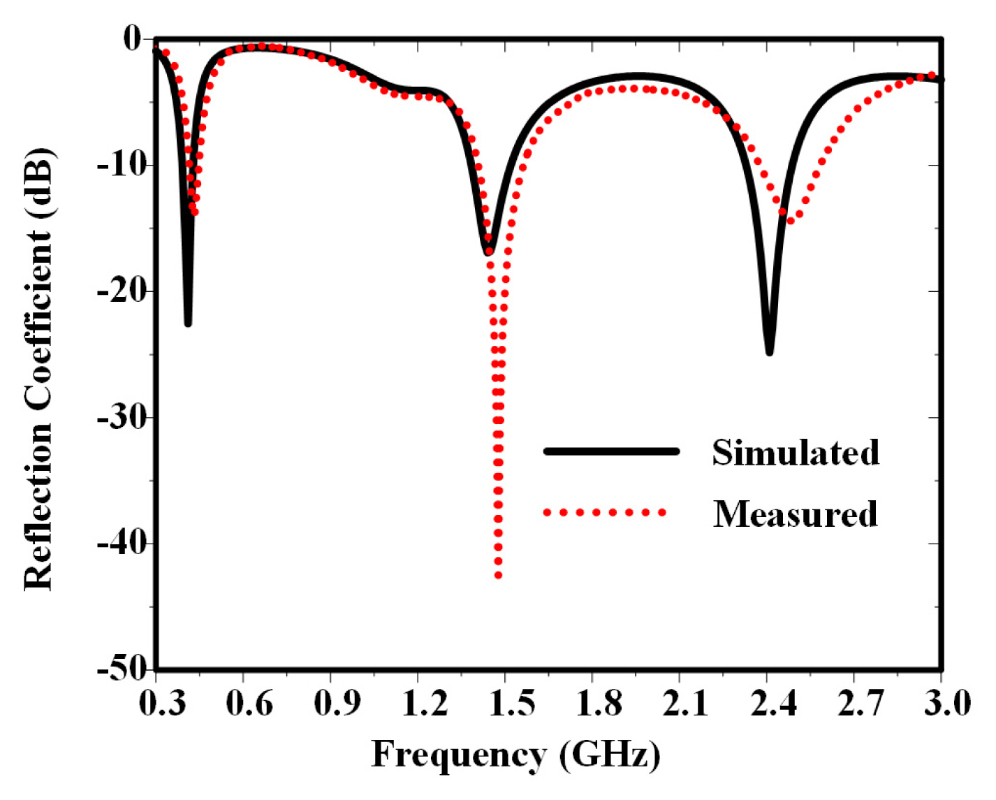
The fabricated prototypes are shown in Fig. 4(a), and the substrate and superstrate are glued together. Moreover, the measurement setup for the proposed antenna is shown in Fig. 4(b). The measurement is implemented with the vector network analyzer (VNA Protek A333). The antenna is placed under 5 mm in pork muscle with the size of 100 mm × 100 mm × 50 mm, and connected to the feeding port. The dielectric property of the pork muscle for measurement is similar to human tissue. The comparison of reflection coefficients between the simulation and measurement results is presented in Fig. 5. It can be seen that the proposed antenna exhibits resonant frequencies at 402 MHz, 1.4 GHz, and 2.45 GHz with impedance bandwidths at −10 dB of 10.1% (390.3–431.2 MHz), 15.7% (1.38–1.6 GHz), and 9.58% (2.37–2.6 GHz). These bandwidths are wide enough for the MICS (401–406 MHz), WMTS (1,395–1,400 MHz, 1,427–1,432 MHz), and the ISM band (2,400–2,500 MHz). The difference between the measurement and simulation results due to fabrication tolerance is negligible. The far-field radiation patterns are measured in a microwave chamber, as shown in Fig. 4(c). Fig. 6 shows a comparison of the simulated and measured radiation pattern results on the XOZ and YOZ planes at the triple desired frequencies. The peak gains are −35.7 dBi, −25.1 dBi, and −19.5 dBi at 402 MHz, 1.4 GHz, and 2.45 GHz, respectively. At 402 MHz (MICS) and 1.4 GHz (WMTS), the radiation patterns are nearly omnidirectional, which is an advantage in communication. Meanwhile, directional radiation at 2.45 GHz (ISM) could be achieved with a high gain, improving the performance of wireless power transfer. A slight difference between the measured and simulated results is recorded due to the unstable position of the antenna in the muscle tissue.

Fabricated and measured implanted antenna: (a) antenna fabricated prototypes, (b) setup for the reflection coefficient measurement, and (c) setup for the radiation pattern measurement.

Comparison of simulated and measured radiation patterns: (a) 402 MHz, (b) 1.4 GHz, and (c) 2.45 GHz.
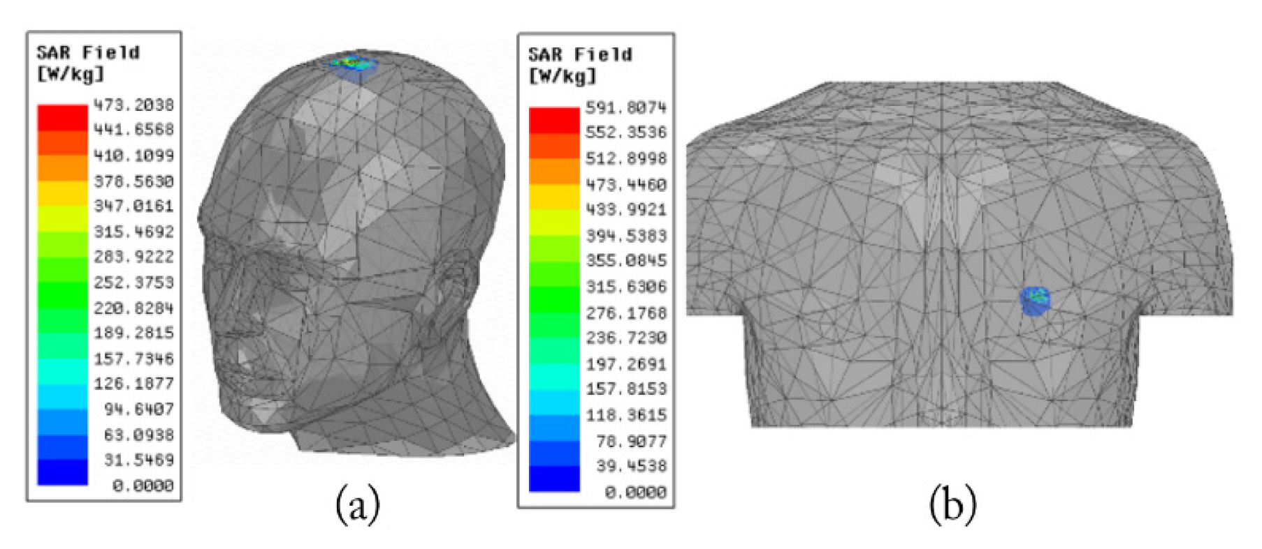
The SAR value verifies electromagnetic field absorption in the human body. The greater the SAR value, could cause burns inside the human tissue. The SAR value of the proposed antenna is calculated in various implantation scenarios, such as in the head model and the human torso as illustrated in Fig. 7. With an input power of 1 W (30 dBm), the peak SAR values are 473.2 W/kg and 591.8 W/kg over the head model and the human torso, respectively. At a frequency range from 100 kHz to 300 GHz, the SAR is limited to 1.6 W/kg over 1-g of human tissue [15]. Therefore, after reducing the antenna input power to keep SAR within the safety limit, the threshold power for the implanted antenna is 3.45 mW for the head and 2.81 mW for the torso. The detailed SAR values and corresponding allowable maximum input power at the triple band are shown in Table 2. On the other hand, Table 3 shows a summarized comparison of the proposed antenna with related studies in terms of antenna type, dimensions, operating frequency, bandwidth, and peak gain [7, 9–11, 16–18]. The proposed antenna can be seen to have advantages in compactness and uniform bandwidth at triple frequencies, but the gain remains limited by its small size.

Average SAR distribution of 1-g for the different implantable scenarios: (a) head model and (b) human torso.
IV. Conclusion
In this paper, a triple-band ML antenna is proposed for implantable biomedical applications. The antenna is composed of an ML conductive with a shorting pin and a ground slot, and operates at the MICS band (401–406 MHz), WMTS band (1,395–1,400 MHz, 1,427–1,432 MHz), and ISM band (2.4–2.5 GHz) with impedance bandwidths of 10.1%, 15.5%, and 9.58% and peak gain of −35.7 dBi, −25.1 dBi, and −19.5 dBi at 402 MHz, 1.4 GHz, and 2.45 GHz, respectively. The miniaturized implantable antenna with dimensions of 8.1 mm × 8.1 mm (volume of 41.9 mm3), simultaneously operates in two modes: power transmission and data telemetry. The proposed antenna is fabricated and measured to verify the simulation results.
Acknowledgments
This work was supported by the Basic Science Research Program at the National Research Foundation of Korea (NRF), funded by the Ministry of Science and the Information and Communications Technology (ICT) (No. NRF-2017R1A5A1015596).
References
Biography

Lam Vu Tung received his B.S. degree from the School of Electronics and Telecommunication, Hanoi University of Science and Technology, Hanoi, Vietnam, in 2019. He is currently pursuing a Ph.D. degree in the Department of Information and Communication Convergence, Soongsil University, Seoul, Korea. His current research interests include wireless power transfer, antenna design, and biomedical implanted devices.

Chulhun Seo received his B.S., M.S., and Ph.D. degrees from Seoul National University, Seoul, South Korea, in 1983, 1985, and 1993, respectively. From 1993 to 1995, he served as a technical staff member at the Massachusetts Institute of Technology (MIT), Cambridge, MA, USA. From 1993 to 1997, he was an assistant professor at Soongsil University, Seoul. From 1997 to 2004, he was an associate professor at Soongsil University. From 1999 to 2001, he was a visiting professor at MIT. Since 2004, he has been a professor of electronic engineering at Soongsil University. From 2011 to 2014, he was chairperson of the IEEE microwave theory and techniques (MTT) Korea Chapter. He is currently the president of the Korean Institute of Electromagnetic Engineering and Science (KIEES). He is also the director of the Wireless Power Transfer Research Center (which is supported by the Korean government’s Ministry of Trade, Industry and Energy); the Metamaterials Research Center (which is supported by Basic Research Laboratories (BRL) through the NRF grant funded by the Ministry of science, ICT and future planning (MSIP); and the Center for Intelligent Biomedical Wireless Power Transfer (which is supported by the National Research Foundation of Korea [NRF] funded by the MSIP). His research interests include wireless technologies, RF power amplifiers, and wireless power transfer using metamaterials.


