I. Introduction
The rapid advancement of radio-frequency identification (RFID) technology and its wide range of applications have necessitated the development of smaller, low-profile components that may be used in RFID systems [1, 2]. This technology is widely utilized in a variety of fields, including automatic sales management, security and access control, industry and manufacturing, and transportation and distribution systems [2]. A basic RFID system consists of two major components: a reader and tags [1–3]. Passive, semi-passive, and active are the three types of RFID tags. Passive tags are cheap and have a nearly indefinite lifetime. As a result, they make up the vast majority of transmitters and receivers used in RFID applications [2, 3]. They may operate in a variety of frequency bands, with the most popular being 125 kHz, 13.56 MHz, 860–960 MHz, and 2.4 GHz. Low-frequency (LF) and high-frequency (HF) systems (125 kHz and 13.56 MHz, respectively) have a 1-m operational range. Ultra-high frequency (UHF) transmitters and receivers, however, operate in the far-field area with radiative coupling over extended operational distances of several meters [3, 4].
In recent decades, ultra-wideband (UWB) technology has been considered a solution to solve the weaknesses of UHF methods and their inability to define RFID systems. UWB communication systems have gained importance in recent years.
Minimizing energy consumption and the environmental effects of RFID systems have been of great interest. UWB-based solutions can be efficiently adapted in this context, as UWB signals can localize and track passive devices and enhance existing systems’ performances [5–10]. Because of its low cost, ease of installation, and high data transfer rate, UWB technology is now widely utilized in modern communication systems. The constant advancement of UWB communication systems has revolutionized printed antenna designs to meet the primary needs of UWB applications. The US Federal Communication Commission (FCC) permitted UWB transmitters to operate in the spectrum from 3.1 to 10.6 GHz in 2002 due to its efficient commercial UWB communication technologies [11]. However, these antennas have serious electromagnetic interference problems, as there are several other narrowband wireless communication systems, such as WLAN (2.4–2.5 GHz), Wi-MAX (3.5–3.7 GHz), high data rate HIPERLAN/2 bands (5.15–5.35 and 5.470–5.725 GHz), and the IEEE 802.11a bands (5.15–5.35 and 5.725–5.825 GHz) functioning in the same frequency spectrum [12–17].
The antenna of the RFID reader was recently updated to include triple-band UHF and UWB technologies. UWB-UHF RFID systems have been examined, and various solutions for UWB and UHF antennas have been proposed in the literature [18–22]. For example, a dual-band circularly polarized antenna was fabricated in [20] and implemented in UHF-UWB RFID applications. In [21], researchers developed a hybrid passive UHF/UWB RFID antenna for passive indoor identification and localization systems. An integrated UWB/UHF antenna utilizing a single port for localization and energy harvesting was created in [22].
This paper presents the first antenna solution for UWB/UHF RFID systems operating in the 0.5–12 GHz bands. The RFID reader board has a triple-band antenna built in. In addition, a UHF/UWB reader antenna with triple-band characteristics was developed and implemented using a coplanar waveguide (CPW). It has a simple structure with few geometric characteristics and a small dimension. Its excellent characteristics (compact size, high gain, large bandwidth, omnidirectional H-plane, and E-plane radiation pattern across the operating bands) make it a promising solution for UHF/UWB RFID systems. An integrated scheme is made up of a reader module, a triple-band antenna, and an STM32L476RG microcontroller. The RFID reader antenna was simulated using CST Studio Suite, and a prototype antenna was incorporated into the system board for near- and far-field communication. In fact, the integrated antenna scheme shows good performance when implemented in RFID applications, as it can attain the UHF and UWB frequency triple bands.
The following is a breakdown of the manuscript’s structure. The UHF/UWB antenna RFID reader design with the triple band is presented in Section II. Section III illustrates how different factors impact the antenna reader’s performance. The electromagnetic simulation environment and experimental setup where the simulation and measurement findings were achieved are then depicted in Section IV. The integrated modeling of a triple-band antenna RFID reader system in the RFID board is discussed in Section V. In the final section, the proposed antenna is compared to those in recent literature, and a conclusion is presented.
II. Design of the UHF/UWB Antenna Reader
Due to their simple construction, ease of manufacturing, good wideband properties, and omnidirectional radiation patterns, circular disc monopole antennas are promising solutions for UHF/UWB RFID applications [23–26].
1. RFID Reader Antenna Design with Triple Bands
The UWB monopole antenna has a circular shape. The ground plane is characterized by a coplanar configuration proportional to the excitation line. It is fed with a microstrip feed line with characteristic impedance of 50 Ω.
A circular patch printed on a low-cost FR4-type substrate with a thickness h = 0.8 mm, relative permittivity ɛr = 4.3, and loss tangent tan δ = 0.025 was utilized to fabricate the antenna whose geometry is presented in Table 1. The substrate had a total size of 70 mm × 60 mm × 0.8 mm. The ultra-wide impedance bandwidth was achieved using CST software to simulate a compact structure. Fig. 1 shows the final design for a triple-band monopole antenna. The main aim of this study was to create a triple-band antenna reader for UHF/UWB operation. A circular patch disc monopole antenna with two-sided corner truncation and two circular and (+)-shaped slots make up this antenna [27].
2. Antenna Reader Design Procedure
Fig. 2 depicts the evolution of the introduced triple-band antenna from the basic UWB antenna step by step.
There are three basic phases in the antenna design process. The circular patch-based CPW that feeds the antenna with a ground plane in Ant.0 is distinguished by its proportional coplanar design. The prior base antenna was changed to improve antenna performance and build a UWB antenna, although geometrical characteristics and the substrate remained the same as the basic antenna.
In Ant.1, a two-sided corner truncation method was used to truncate the patch antenna corners. The specifications of the truncated corners utilized to increase bandwidth and provide better impedance matching throughout the operating bands are shown in Fig. 2 (Ant.1).
To achieve the UWB response, the slots (+) and circular shapes were etched into the circular patch with a length (Ls), width (Ws), and circle radius (r) in Ant.2. Compared to the previous UWB antenna, impedance matching and operational bandwidth were significantly improved in the initial iteration.
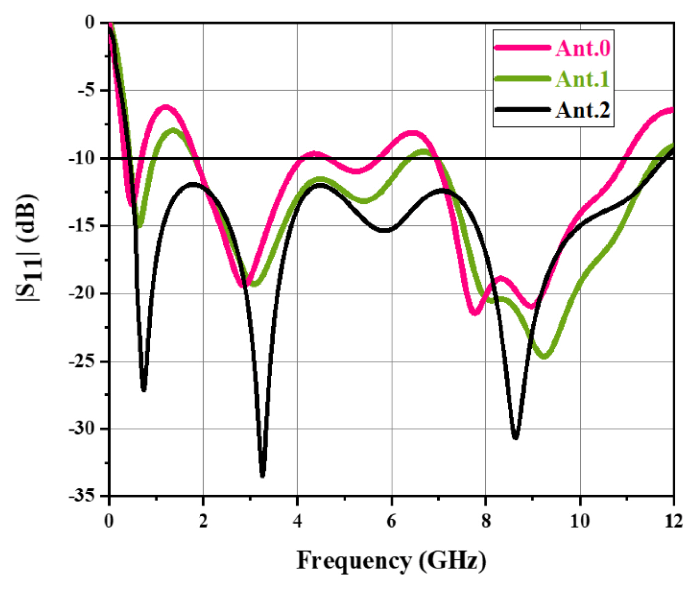
Fig. 3 shows the reflection coefficient S11 versus the frequency of the proposed antenna compared to the other antennas. The antenna (Ant.0) demonstrated broad capabilities with a −10 dB bandwidth spanning 1.8–4.5 GHz (2.7 GHz) and 7–11 GHz (4 GHz).
The antenna (Ant.1) had a fractional impedance bandwidth spanning from 1.8 to 6.5 GHz (4.7 GHz) and 7 to 11.8 (4.8 GHz) in this design stage, indicating an increase in the bandwidth that is nearly equivalent to 2.8 GHz in contrast to the bandwidth given by the present UWB antenna.
By putting the slots—circular and (+) forms—in the radiating patch, Ant.2 attained a −10 dB bandwidth in the 0.5–12 GHz (11.5 GHz) range, which covers WLAN (2.4/3.2/5.2/5.8 GHz) and Wi-MAX (3.5/5.5 GHz).
III. Parameters Analysis of UWB Antenna Reader
To demonstrate how different parameters affect antenna performance, four parameters were optimized to obtain all triple bands. These parameters were stub length (t), slot length (Ls), width (Ws), and the dimension of the outer radius (r), all of which had a significant impact on the proposed antenna’s bandwidth performance.
1. Effect of Truncation Length (t)
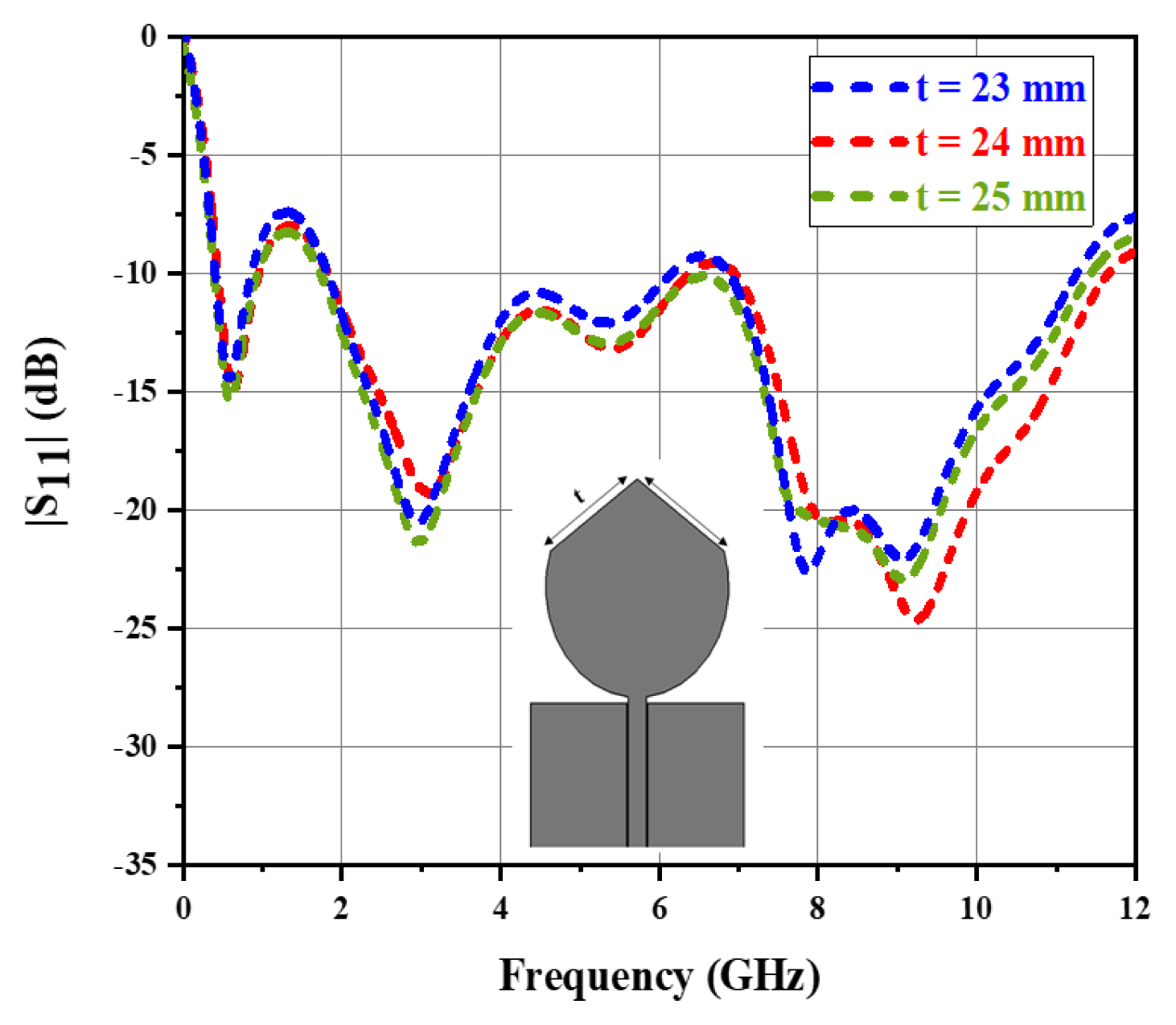
Fig. 4 shows the effect of the truncation length (t) on the S11 performance of the proposed antenna. The antenna’s impedance matching performance was harmed by truncation (t). To achieve a bandwidth appropriate for triple-band performance, the maximum value of truncation (t) was set to 24 mm.
Fig. 4 shows the bandwidth performance of the reflection coefficient S11 in the 1.8–4.5 GHz and 7–11 GHz frequency bands with t = 24 mm. Obviously, when the truncation length was increased, the antenna impedance matching deteriorated (t).
2. Effects of the Length (Ls) and Width (Ws) of the Form Slot (+)
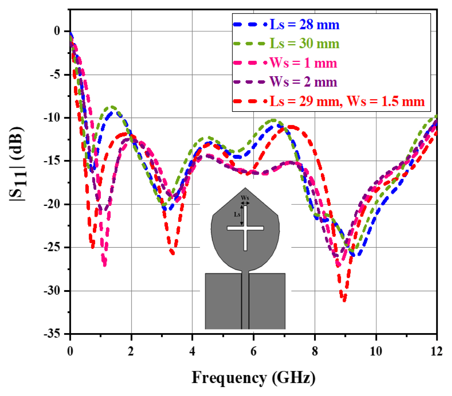
Fig. 5 shows the impact of different slot lengths (Ls) and widths (Ws) on the bandwidth. The antenna performance was analyzed using a slot with three unique lengths and widths, Ls = 15, 16, and 17 mm, and Ws = 0.5, 1, and 1.5 mm, while the other parameters remained at their final values.
The slot with a reduced length (Ls = 28 mm) showed a poor reflection coefficient at a higher frequency in the range of 0.5–1.5 GHz. An increase in slot length at Ls = 30 mm enhanced the reflection coefficient performance at a higher bandwidth of 0.5–1.5 GHz but resulted in poor impedance matching varying between 8 and 11 GHz. Nevertheless, the substrate slot’s optimal length (Ls = 29 mm) provided good impedance matching over the required frequency band, and it showed that the UWB width of the antenna was in the range of 0.5–12 GHz. Fig. 5 depicts the influence of the slot width Ws on the impedance bandwidth. The antenna achieved the desired UWB width with acceptable impedance matching by increasing the slot width by 1 mm. In the frequency range of 4.6–6.5 GHz, a further decrease in the slot width (Ws = 1 mm) resulted in an impedance matching issue, whereas increasing the slot width (Ws = 2 mm) contracted the impedance bandwidth. As a result, we can see that for Ws = 1.5 mm, a maximum impedance bandwidth with the best impedance matching was supplied.
3. Effects of the Radius of the Circular Slot (r)
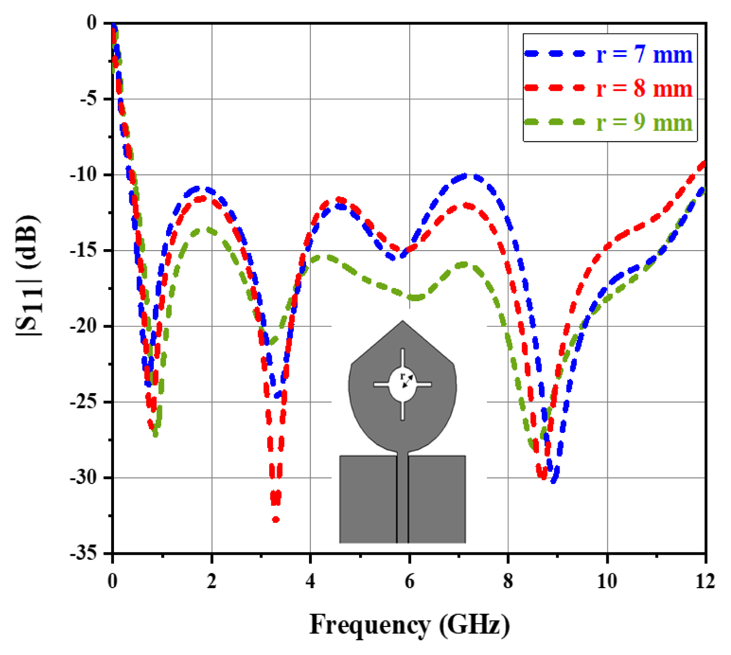
The patch outer radius was altered when the dimensions of the remaining radiating parameters were fixed at their final values. Fig. 6 shows the simulated S11 curves for various values of the patch’s outer radius (r). Changing the antenna’s remaining settings obviously changed the antenna’s initial resonance frequency. In actuality, the outer radius (r) was between 7 and 9 mm, with a 1-mm step size. This figure also shows the simulated reflection coefficient S11 of the proposed UWB antenna with a varied slot circular radius on the patch. At a larger radius of r = 9 mm, it was evident that the antenna did not create an ultrawide impedance bandwidth.
Fig. 6 further shows that the antenna had a low reflection coefficient performance for r = 7 mm frequency bands ranging from 3.1 to 6.8 to 7.1 GHz.
The antenna created only two rejection frequency bands spanning from 5.25 to 5.95 GHz and 2.5 to 7.8 GHz when the (r) parameter was increased by 1 mm (r = 9 mm). Thus, for the constructed antenna, the optimum radius dimension of r = 8 mm was taken into consideration.
To sum up, if the antenna was constructed with t = 24 mm, Ls = 29 mm, Ws = 1.5 mm, and r = 8 mm, it produced a triple band with a high impedance bandwidth.
The measurement findings of the suggested antenna design, reflection coefficient S11, gain, and radiation pattern features are illustrated and discussed in the next section.
IV. Measurement Results and Discussion
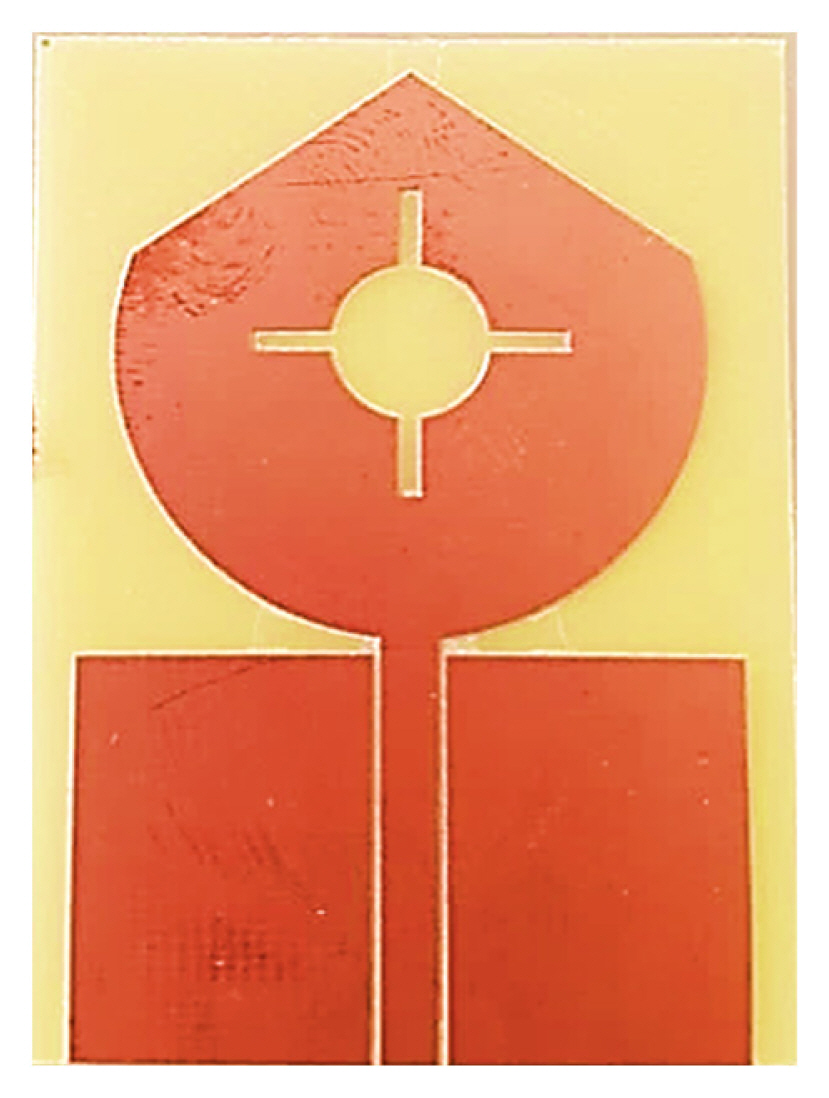
The measurement results were compared to the simulated performance of the introduced antenna with an optimum size. Fig. 7 shows a constructed prototype of the microstrip-line-fed triple-band antenna.
The Agilent PNA Network Analyzer (N5221A) was used to assess the antenna’s reflection coefficient S11 measurement. The anechoic chamber was used to measure the other antenna parameters, such as the radiation pattern and gain performance.
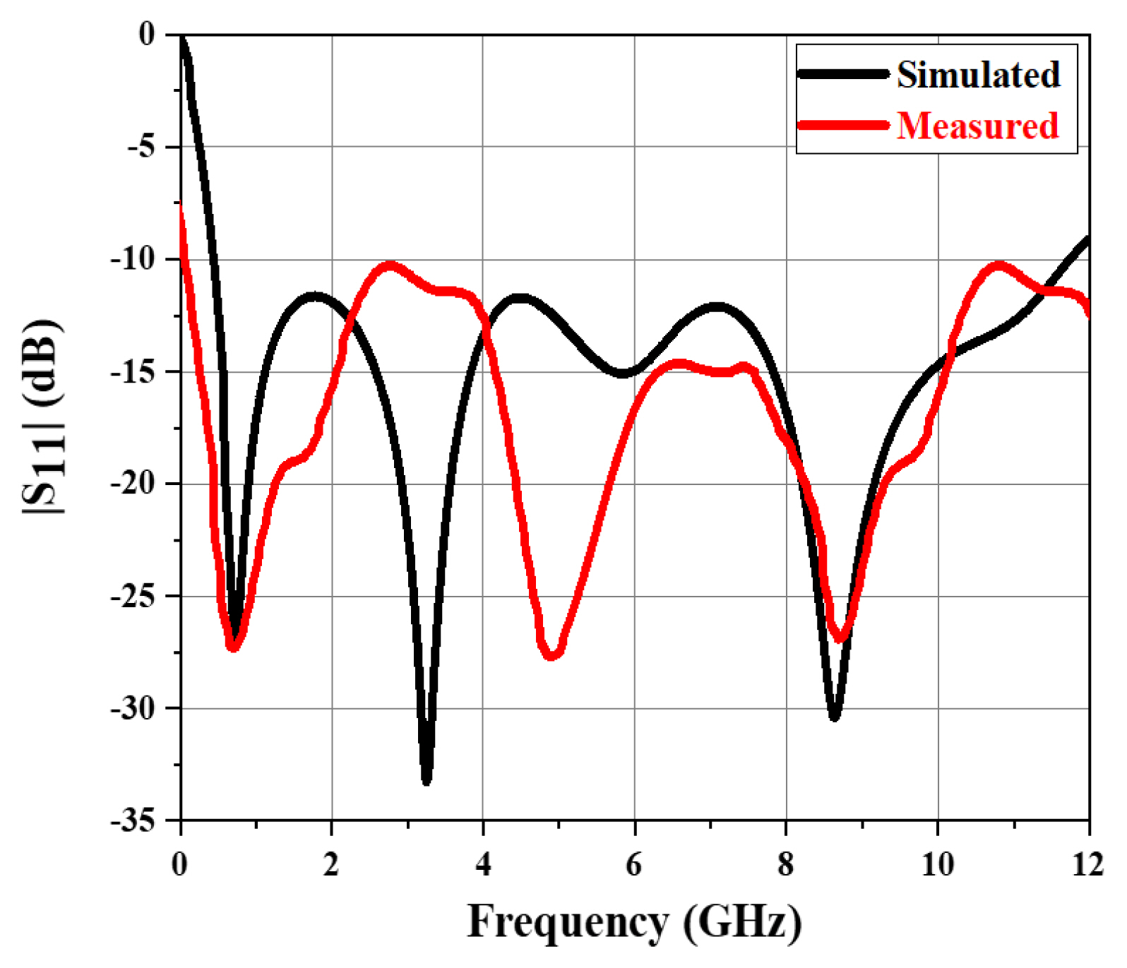
Fig. 8 presents the measured and simulated reflection coefficient S11 curves of the UHF/UWB reader antenna.
The observed results are fairly similar to the simulated ones, revealing an ultra-wide working frequency band. For |S11| < −10 dB, the reflection coefficient bandwidth varied between 0.5 and 12 GHz, spanning the UHF/UWB working frequency band. The second resonant frequency at 5 GHz was moved to a higher frequency when comparing the simulated and measured results.
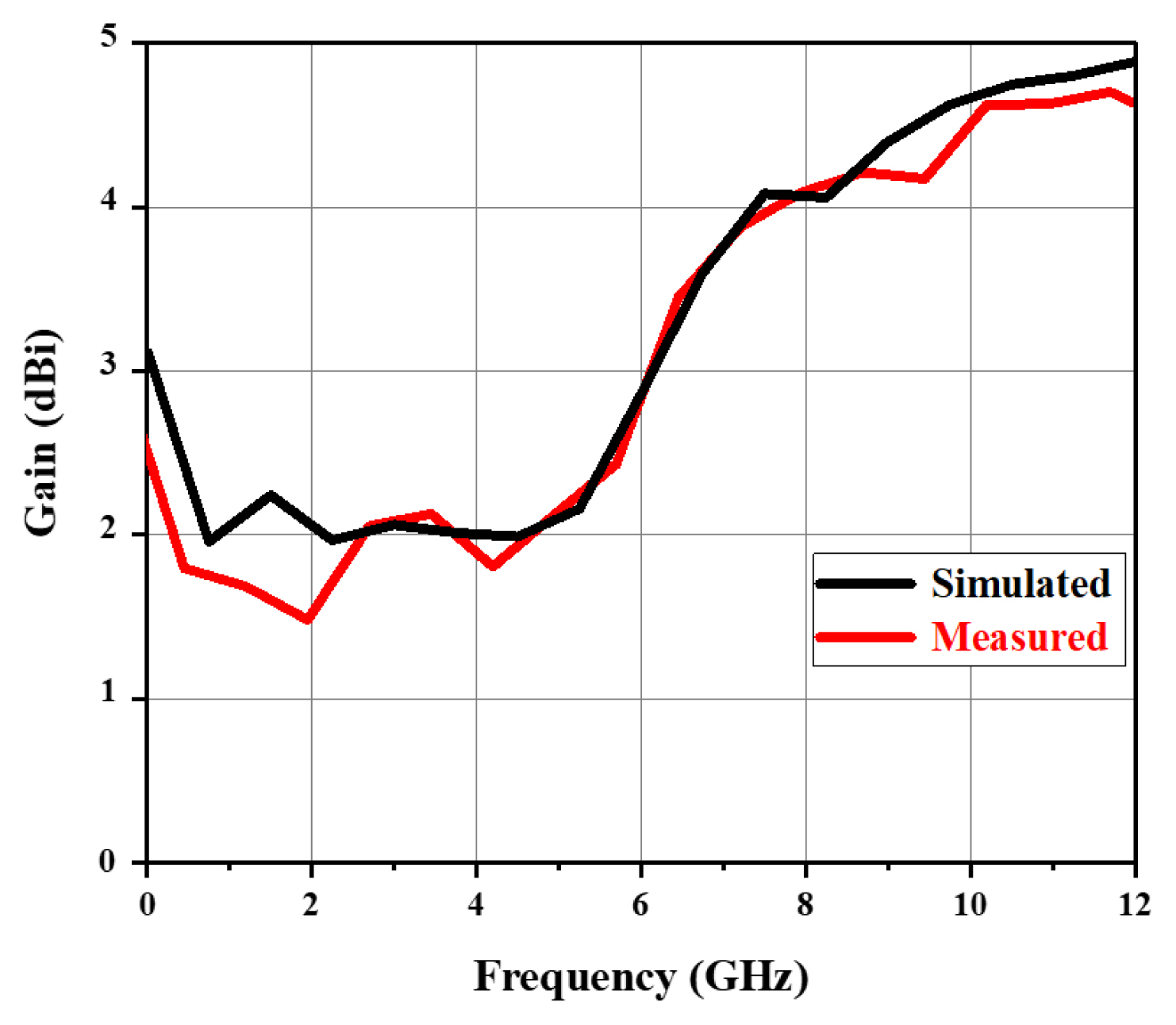
Fig. 9 shows the simulated and measured gain variations of the proposed UHF/UWB reader antenna. The antenna provides a gain performance of 4.8 dBi as a function of frequency.
The ambient influence, manufacturing tolerances, substrate losses, and SMA connection loss all contributed to the insignificant difference between the simulated and measured results. The described RFID reader antenna design has numerous advantages, including its compact size, ease of manufacturing, easy matching, and ability to display a triple band.
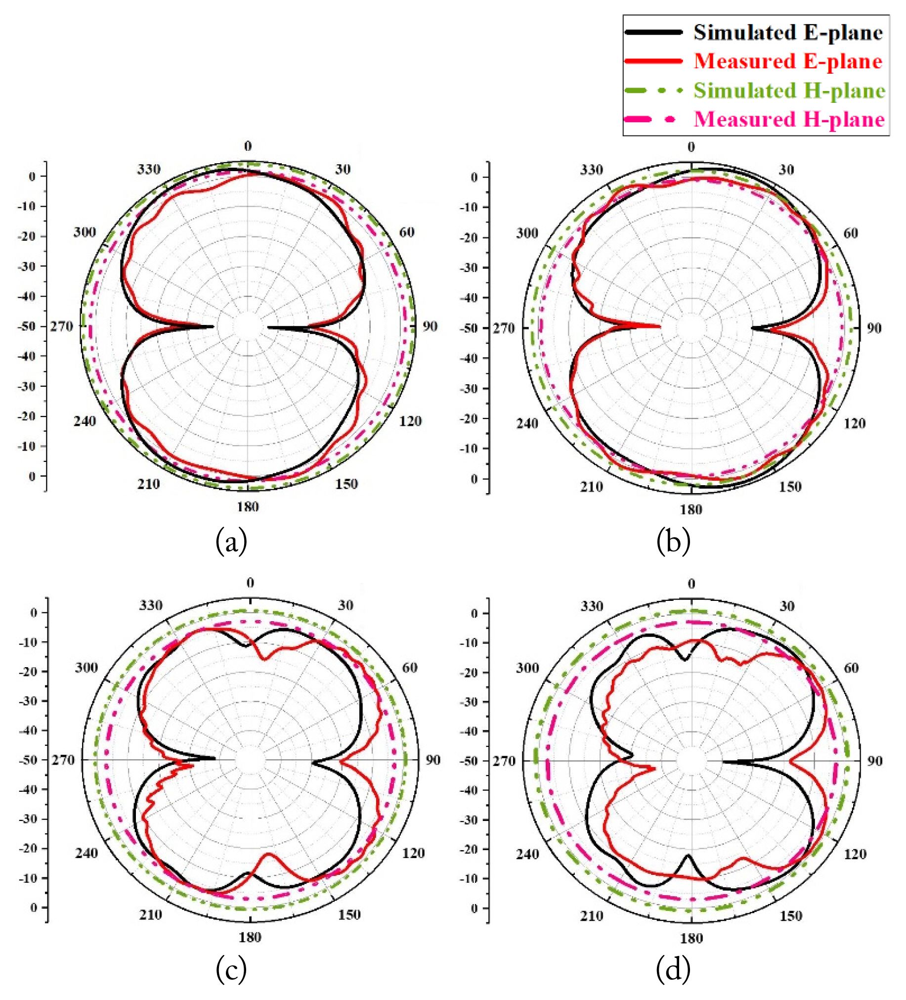
The radiation patterns revealed the antenna’s radiation performance in the operational bands. Fig. 10 shows the simulated and measured antenna radiation patterns in the E-plane (yz-plane) and H-plane (xz-plane) in an anechoic chamber. The prototype RFID reader antenna’s observed radiation patterns in the E-plane and H-plane at the four resonant frequencies of 1, 3, 7, and 10 GHz correspond well with the simulations. The designed antenna produced stable patterns over the entire working band in both the E- and H-planes. In the H-plane, the proposed antenna clearly provided omnidirectional radiation patterns.
V. Integrated Modelling of the Triple-Band RFID System
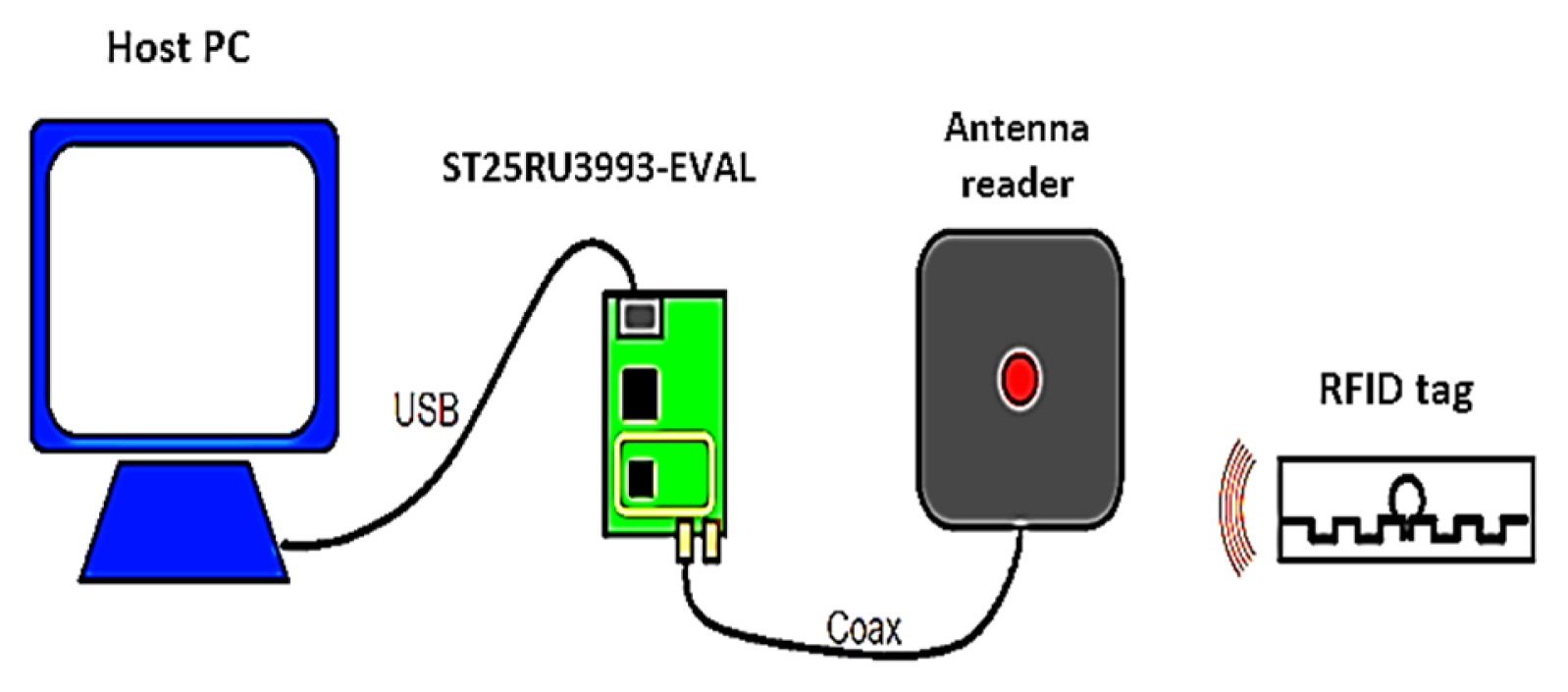
A simple RFID system consists of an antenna reader, an RFID tag, and a host PC for data visualization and management. The first component is a tag that is applied to an item that is to be identified and located among hundreds or thousands of others. It has a tiny antenna that is linked to a microchip by a small memory that stores the object’s identity and data [28]. When the tag is positioned in the scanning environment, the RFID reader is a scanner placed in a fixed spot to interrogate it. The host PC acts as a data processor, controlling, displaying, and storing information from the tag and reader. The RFID system is shown in Fig. 11.
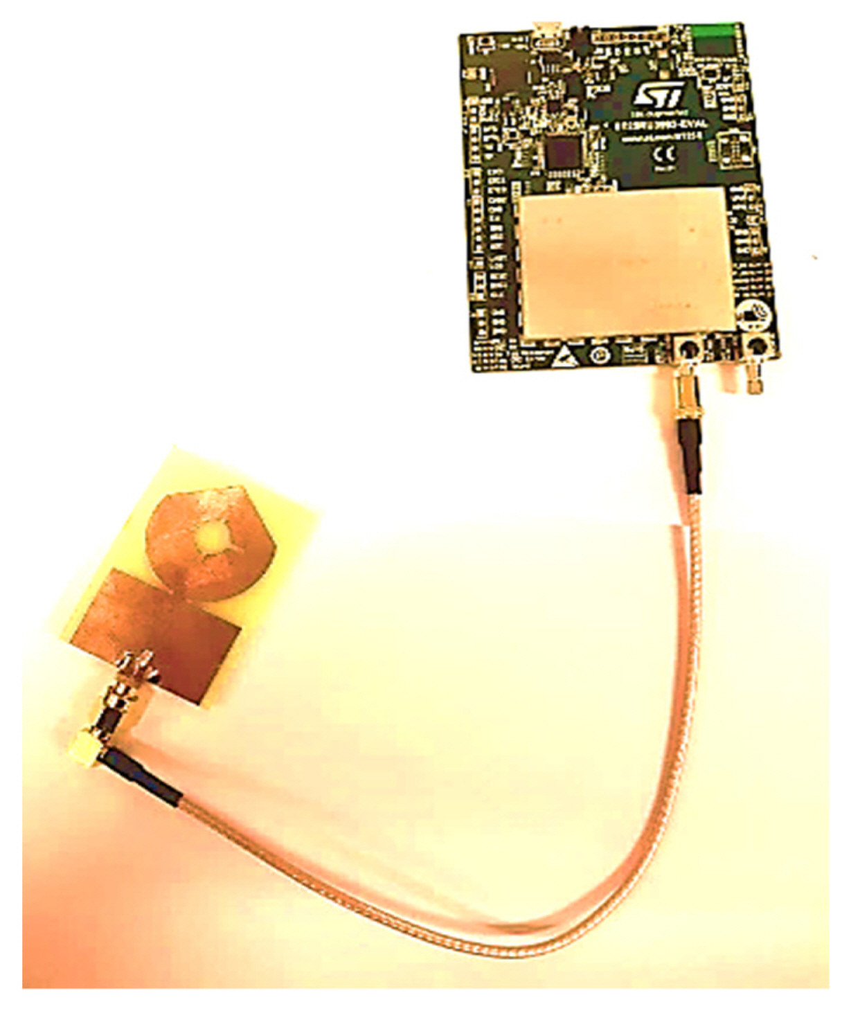
The proposed antenna operating simultaneously in both UHF/UWB bands is integrated into the RFID reader board to read the identification of RFID tags through the RFID module, which is connected in series with our antenna. Fig. 12 illustrates the schematic of the triple-band antenna integrated in the RFID reader board.
The proposed antenna operating simultaneously in both UWB/UHF bands was integrated into the RFID reader board to read the identification of RFID tags through the RFID module, which was connected in series to our antenna. Fig. 12 illustrates the schematic of the triple-band antenna integrated in the RFID reader board.
The RFID reader board is made up of three parts: hardware, antenna, and software. The first has a reader antenna, an RF module, and an STM32L476RG microprocessor. Through a serial link, the host PC and the RFID reader board interact.
The ST25RU3993-EVAL board supports a frequency channel within the range of 840–960 MHz. A graphical user interface (GUI) running on a host PC through a USB/UART bridge controls it.
The tag display was managed inside the interface of the ST25RU3993 GUI software program using an algorithmic technique built within the microcontroller. An RFID reader board and a UHF 860–960 MHz passive RFID tag were utilized in the prototype antenna test.
Fig. 13 describes the typical reader setup. The connection between the host PC running the GUI and the ST25RU3993-EVAL board was ensured by a USB cable. The antenna was linked to the antenna port via a 50 Ω coaxial cable. Since the mentioned prototype could read the RFID tags, they were within the range of the antenna reader. Reader antenna performance was studied when integrated into the RFID board and after reading tags UHF.
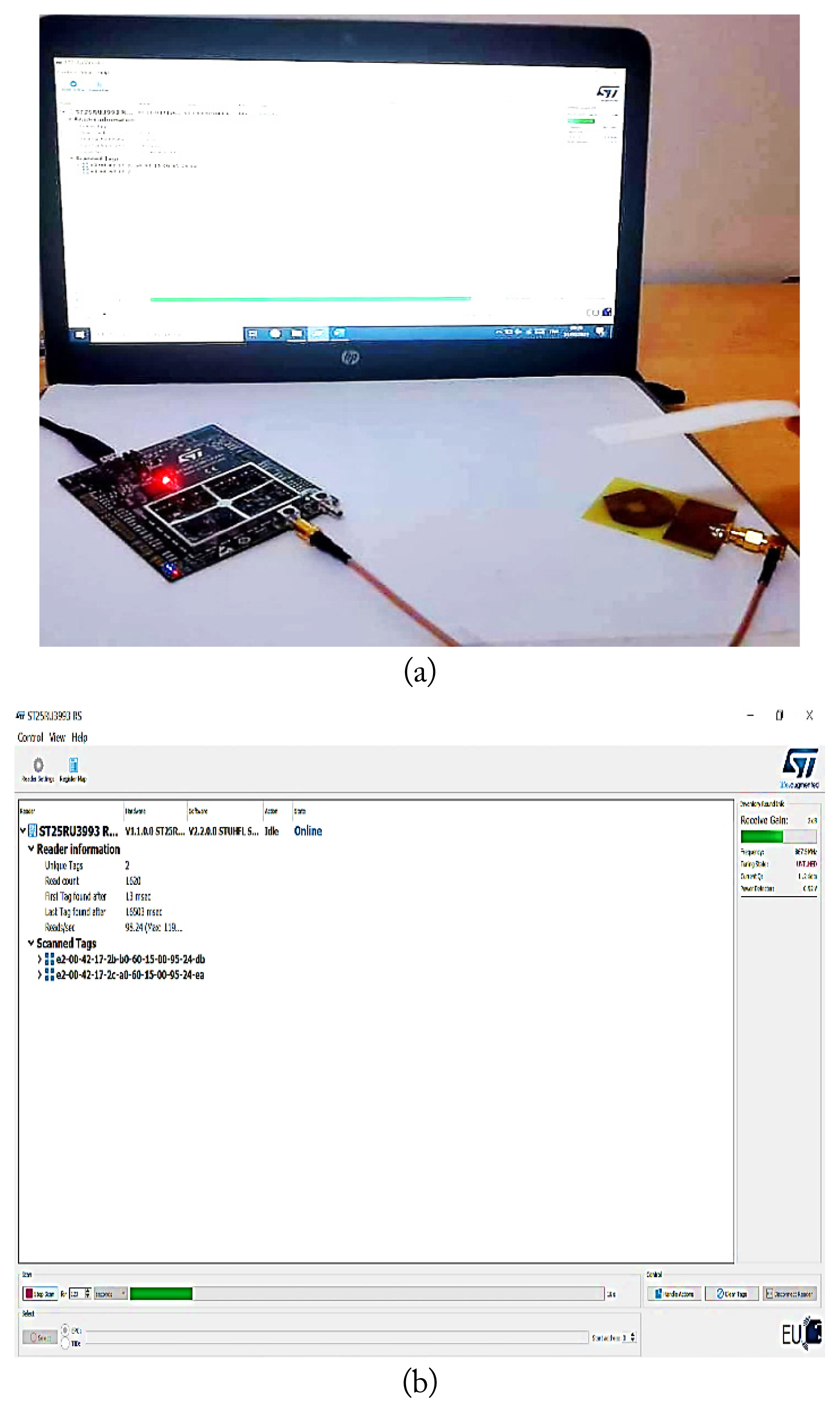
The reader antenna reads tags through the ST25RU3993 GUI software application. The reading experiment between the UHF reader antenna and the UHF tag antennas integrated into the ST25RU3993 GUI software application is presented in Fig. 13(a).
The distances from the board to the UHF tag varied from 5, 7, 9, 11, and 13 m. The UHF RFID tag’s reading performance was inversely associated with the distance between the board and the tag—in other words, the reading performance deteriorated with the increase in the distance between the board and the tag. Fig. 13(b) shows the main window of the ST25RU3993 GUI.
VI. Comparison and Novelty
In terms of size, bandwidth, gain, and operational frequency range, Table 2 shows the comparison results regarding the performance of the planned UHF/UWB triple-band antenna to that of the current antennas [18–20, 29–31]. The results showed that the created reader antenna’s uniqueness offered good impedance bandwidth and gain performance, and its applicability was demonstrated by utilizing a UHF/UWB triple-band monopole antenna incorporated into an RFID reader board. The advantages of the developed antenna demonstrate its uniqueness in the field of triple-band UHF/UWB RFID reader antennas.
VII. Conclusion
This study proposed a novel approach of integrating a triple-band monopole antenna with UHF/UWB (0.5–12 GHz) into the RFID reader board. The CPW antenna had a microstrip line fed into a circular patch with two truncations and two slots on the patch, (+)–shaped and circular one, to achieve UWB characteristics with three resonance frequencies. Simulations were performed using CST Studio Suite throughout the design process, and the antenna prototype was built and incorporated into the system board for RFID near- and far-field communication applications. We demonstrated the good performance of the proposed antenna and its application in the UHF/UWB communication band with a maximum gain of 4.8 dBi using simulated and measured results. The antenna’s radiation characteristics were also noted to be outstanding over the UHF/UWB spectrum. The new antenna is easier to build than the ones described in the literature, and it has tunable notch characteristics, making it a viable option for UHF/UWB communication systems. The integrated antenna design complies with UHF frequency regulations, making it ideal for RFID applications.