Analysis of Cross-Polarized Field by Panel Misalignment Errors in a Deployable Reflector Antenna
Article information
Abstract
This paper analyzes the generation mechanism of a cross-polarized field resulting from panel misalignment errors in a solid-surface deployable antenna. Misalignment of the panel in a deployable antenna results in path length error and rotation of the unit normal vector on the reflector surface. However, in terms of the analysis of cross-polarization (cross-pol) generation, rotational error is a more significant factor. In the aperture field, the distributions of cross-pol components are calculated to identify the polarization characteristics of the radiated field. For uniform misalignment, the peak-to-cross polarization (XPOL) is found to be smaller than −50 dB for misalignment angles less than 3°. Furthermore, when the panels are non-uniformly misaligned with a sinusoidal distribution, the cross-pol level depends on the angular position of the maximum misalignment.
I. Introduction
Reflector antennas are increasingly being used in small- and medium-sized satellites because they are lightweight and operate over a broad bandwidth. Moreover, deployable reflector antennas can increase the storage efficiency of satellites in launch vehicles. Compared to a mesh reflector antenna, an antenna composed of solid material has higher surface accuracy and possesses the advantage of low cross-polarization (cross-pol) [1, 2]. Recently, the cross-pol characteristics of the antenna have been gaining significance in SAR systems, which can be operated in a polarimetric mode [3, 4]. This is because the cross-polar level in an antenna pattern induces cross-talk in polarimetric SAR images [3].
In a perfect parabolic reflector, cross-polarization is generated by an unbalanced feeder whose feed pattern is rotationally asymmetrical [5]. However, the surface error of the reflector may also generate cross-polarized radiation, even in the case of a balanced feeder. In solid-surface deployable antennas, panels are folded during launch and unfolded during deployment in space [6]. If the antenna is imperfectly deployed in space, the panels are misaligned from the ideal shape [7]. Furthermore, in the case of incomplete deployment, the panels are uniformly misaligned. The panels may also misalign non-uniformly, with the error changing smoothly in the angular direction due to malfunctions in the deployment mechanism. In view of these circumstances, it would be interesting to explore the effects of misalignment error on the radiation pattern of a deployable antenna.
The surface error in a reflector antenna leads to a phase error in the aperture plane due to the path-length difference [8]. For panel misalignment, degradations in co-polarization characteristics are calculated using the aperture phase error (APE) method, which calculates the radiated field from the aperture field by accounting for the phase errors caused by the surface error of the reflector [9]. When the panels are uniformly misaligned, the gain decreases, while the side lobe level also increases with an increase in the error. Apart from this, for an asymmetrical distribution of panel misalignment errors, tilting of the main beam is observed.
Cross-pol in far-field radiation is caused by the cross-pol component in the aperture [5]. However, the APE method does not provide sufficient information when it comes to analyzing cross-pol performances because the cross-polar component is not included in the calculation of the aperture field [8, 9]. When panels are misaligned, the direction of the normal vector on the surface rotates in terms of the misalignment angle, in addition to the path-length difference. In the aperture plane, disturbance of the polarization purity arises from the rotation of the normal vector, as well as from the phase difference. Notably, the rotation of the normal vector is a more important factor in cross-pol generation than the phase difference. Therefore, by investigating the rotational effect of the normal vector on the polarization characteristics in the aperture plane, it is possible to estimate the cross-pol performance of radiation in the far-field region. However, although it is convenient to calculate cross-pol radiation using commercial tools based on numerical methods [10], it is difficult to identify the causes of cross-pol generation resulting from panel misalignments. Therefore, to mitigate cross-pol generation from reflector antennas, a physical understanding of the causes leading to cross-pol occurrence in an aperture is required.
In this paper, the effects of panel misalignment errors on the cross-pol performance of a solid surface deployable antenna are analyzed. To separate the investigation of the influence of the panel error from that of the feeding unbalance, the incident field from the feeder is assumed to be a symmetrical Gaussian beam. The cross-pol performances are analyzed using the aperture cross-pol field (AXPF) method, in which the cross-pol radiation field is calculated from the aperture cross-pol field, which is obtained by counting the effects of the normal vector’s rotation as well as the phase error caused by panel misalignment. In other words, the AXPF method provides a physical interpretation of the mechanism of cross-pol occurrence in the aperture. For some typical types of error distributions, including uniform and cosine shapes, the generation of the cross-pol was analyzed and compared to each other by investigating the aperture field.
II. Cross-Pol Characterization using the Aperture Cross-Pol Field Method
Fig. 1(a) presents the cross-sectional configuration of the reflector of the solid-surface deployable antenna. The reflector consists of a central dish and panels. The diameters of the reflector and the central dish are D and d, respectively. When the panels are completely deployed, the central dish and the panels are assumed to be ideally parabolic with no errors. The feeder is located at the focal point, which is the origin of the coordinates. If the panels are incompletely deployed, the misaligned panel, denoted by a dotted line in Fig. 1(a), is rotated to the misalignment angle α from the ideally aligned panel [9]. The misalignment angle α refers to the angle error of an incompletely deployed panel, which is rotated at the rim of the central dish from the ideal shape, as illustrated in Fig. 1(a). The panel misalignment accompanies the path-length difference from the feeder to the aperture plane, as well as the rotation of the normal vector on the reflector surface. In the AXPF method, the aperture field is calculated by counting the effects of the rotation of the normal vector and the phase error resulting from the path length difference. The unit normal vector of the misaligned panel, denoted by
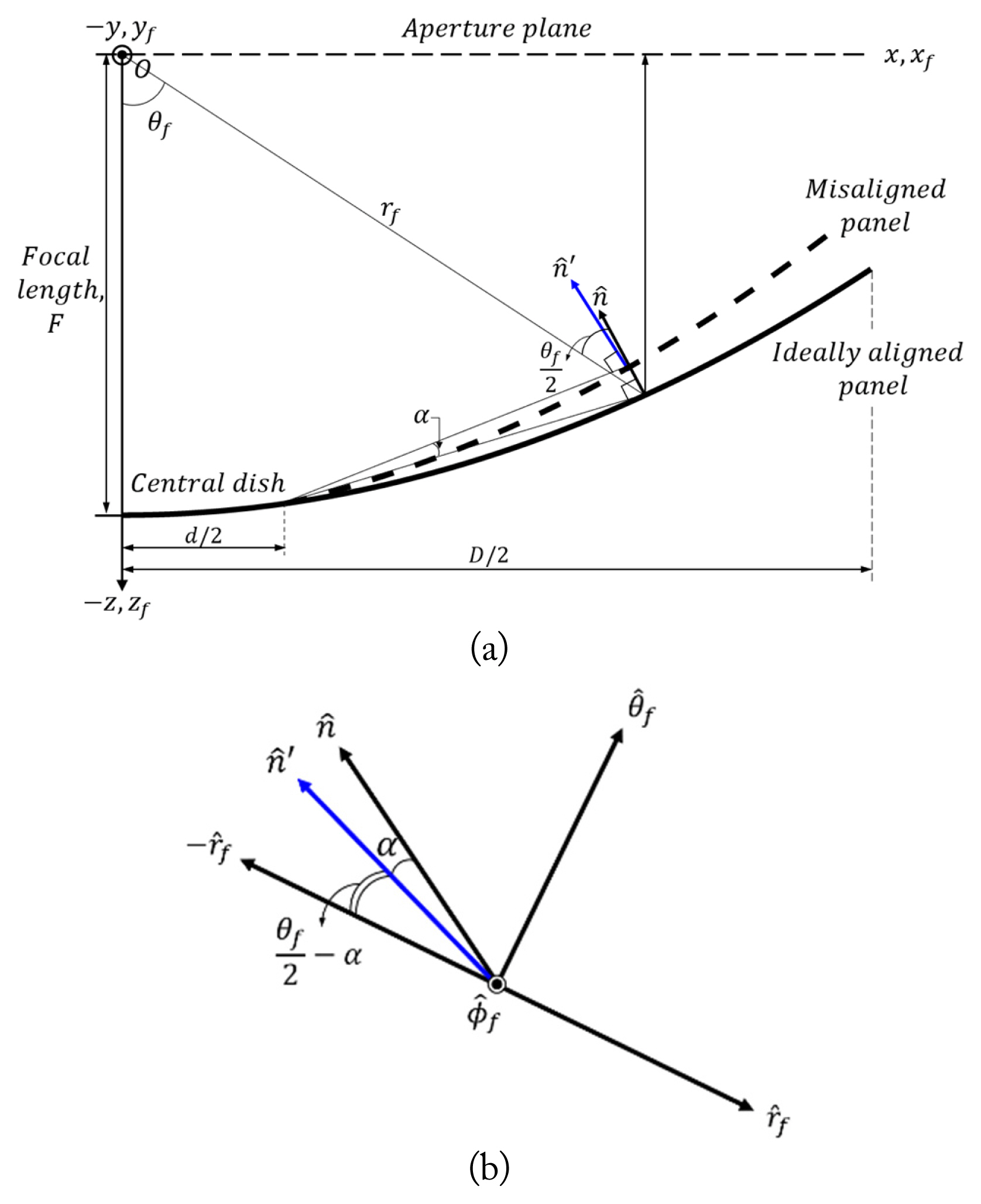
(a) Rotation of the normal vector due to panel misalignment. (b) Normal vector on the rf–θf plane.
To investigate the effects of panel misalignment on cross-pol generation separately from the feeder unbalance, the feeder is assumed to have a balanced pattern in which the E-plane and H-plane patterns are equal. For a balanced feeder with an x-polarized radiation pattern, the incident wave onto the reflector is expressed as [5]:
where C(θf) is the pattern in the E- and H-planes. Furthermore, the reflected wave from the misaligned panel is expressed as Er =2(
where
Here, δm indicates the phase error calculated from the path length error at the m-th panel [8, 9]. In the aperture field expressed in (3), ACO and ACX are the x- and y-direction components that contribute to the generation of co-polarized and cross-polarized radiation fields, respectively. Meanwhile, AZ refers to the z-direction component of the aperture field, which does not contribute to the radiation field. The rotation of the normal vector by angle α and phase error δm result from the panel misalignment. Moreover, since α is small positive when the panel is incompletely deployed, ACO exhibits almost unity although ACX is not negligible for the small α. While the copol radiation degrades mainly due to the phase error δm [9], cross-pol generation is seriously affected by the rotation of the normal vector.
From (4), it is understood that the cross-pol does not occur in the aperture field if the panels are completely deployed (α=0 and
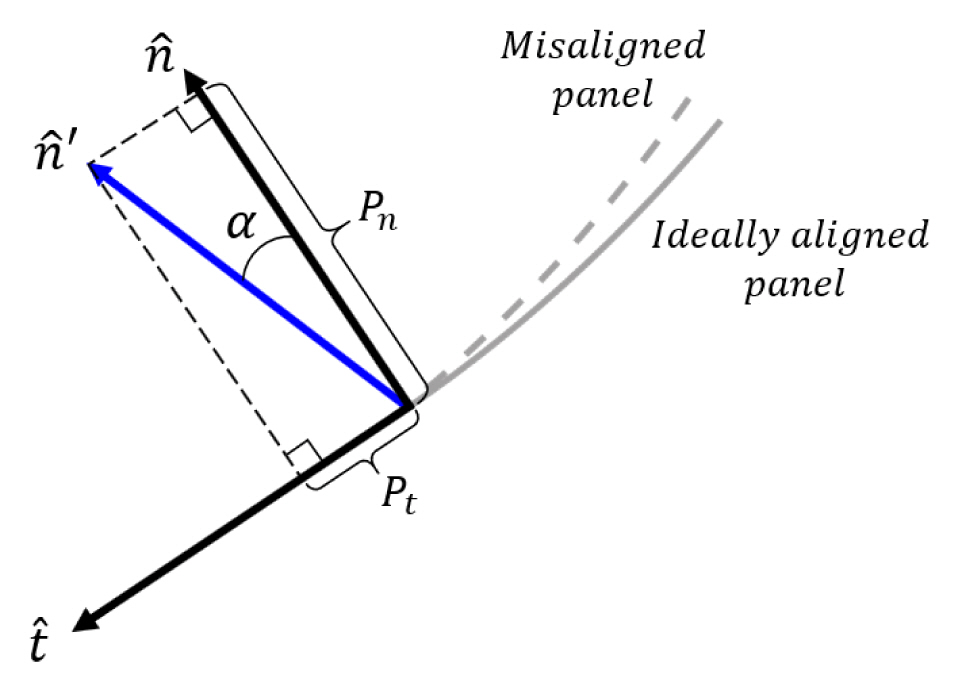
Generation of the components of
where Pn=cosα and Pt =sinα are the normal and tangential components of
Using (2) as an incident x-polarized field from the feeder and
From (7), it is clear that in the rotated unit normal vector
III. Effects of Panel Misalignment on Cross-Pol Radiation
The generation of cross-pol fields due to panel misalignments in the deployable antenna utilized in this research is investigated by analyzing the aperture fields. The diameters of the antenna and the central dish are 1.5 m (D) and 0.2 m (d), respectively. Additionally, the operating frequency is fixed at 9.6 GHz, and the focal length is 0.45 m (F). The number of panels is 30. Furthermore, x-polarized balanced feeding is assumed. Additionally, C(θf) is defined using a Gaussian function when the edge taper is −12 dB.
1. Uniform Panel Misalignment
This section details the analysis of cross-pol characteristics when the misalignment angle (α) is equal for all panels. Since the radiation field is a Fourier integration of the aperture field in (3), the generation of the cross-pol field can be estimated by investigating the behavior of ACX. It has been confirmed that the effect of δm on cross-pol generation is negligible for small α. Drawing on (7),

Distribution of ACX in the aperture for the uniform misalignment error where α is 1°.
The pattern factor of the radiated field in the far-field region can be obtained from the two-dimensional Fourier integral of (3). This integration is performed numerically by dividing the aperture region into trapezoidal micro-regions using a Gaussian quadrature. In radiated electromagnetic fields, the cross-pol field defined by Ludwig [11] is generated from the y-component of the aperture field. Therefore, the distribution of ACX, as shown in Fig. 3, is an important feature in terms of dealing with the cross-pol field.
With regard to the E-plane (φ=0 or π) and H-plane (
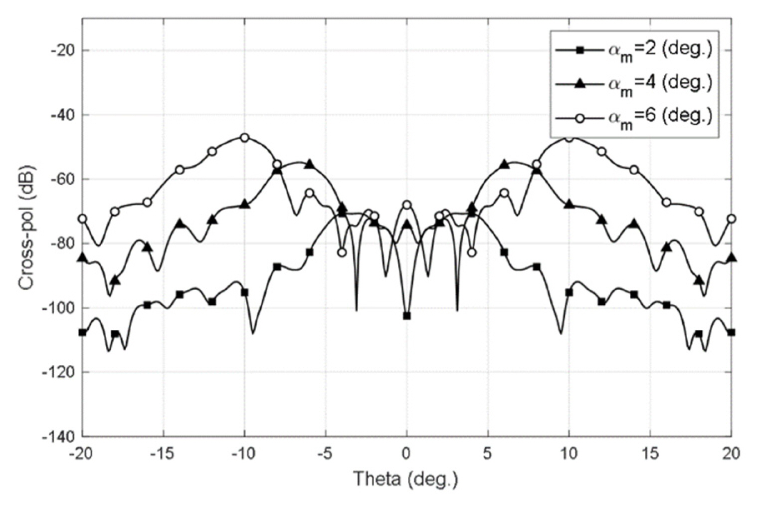
Fig. 4 depicts the cross-pol patterns in the
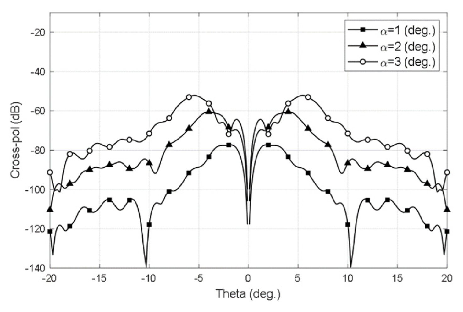
Cross-pol radiation patterns for uniform misalignment errors of panels in the
2. Non-uniform Panel Misalignments
It would be interesting to investigate the generation of the cross-pol field in cases where the distribution of the panel misalignment error is non-uniform. By investigating aperture cross-pol fields, it is possible to estimate the levels of cross-pol radiation for non-uniform panel misalignments. As a typical model of the non-uniform distribution of misalignment errors, we chose sinusoidal functions. Since misalignment angles resulting from incomplete deployment always have a positive value, we assume the misalignment angle of the k-th panel to be:
where k indicates the sequential number of the panel, which increases from the panel at φ=0. Meanwhile, φk denotes the angle in the φ-direction at the middle of the k-th panel, αm indicates the maximum error, and φαm refers to the angle exhibiting the maximum error. Inside the panel, the misalignment angle is assumed to be uniform.
2.1. 1-Cycle Non-uniform Misalignments
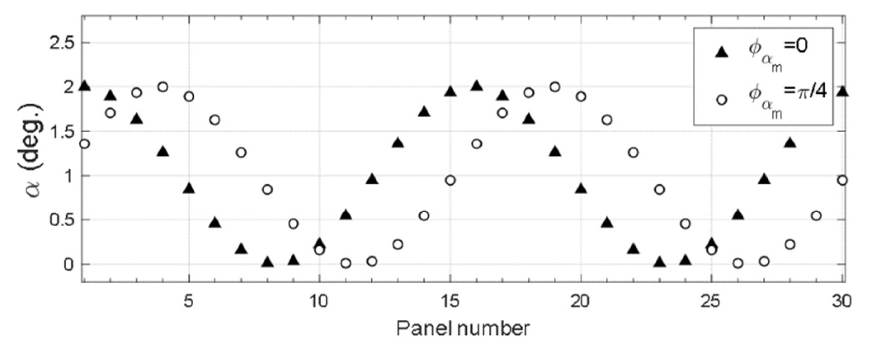
For N = 1, αk varies one cycle for the change of φk from 0 to 2π. Fig. 5 depicts the variations in αk for the panels when φαm=0 and
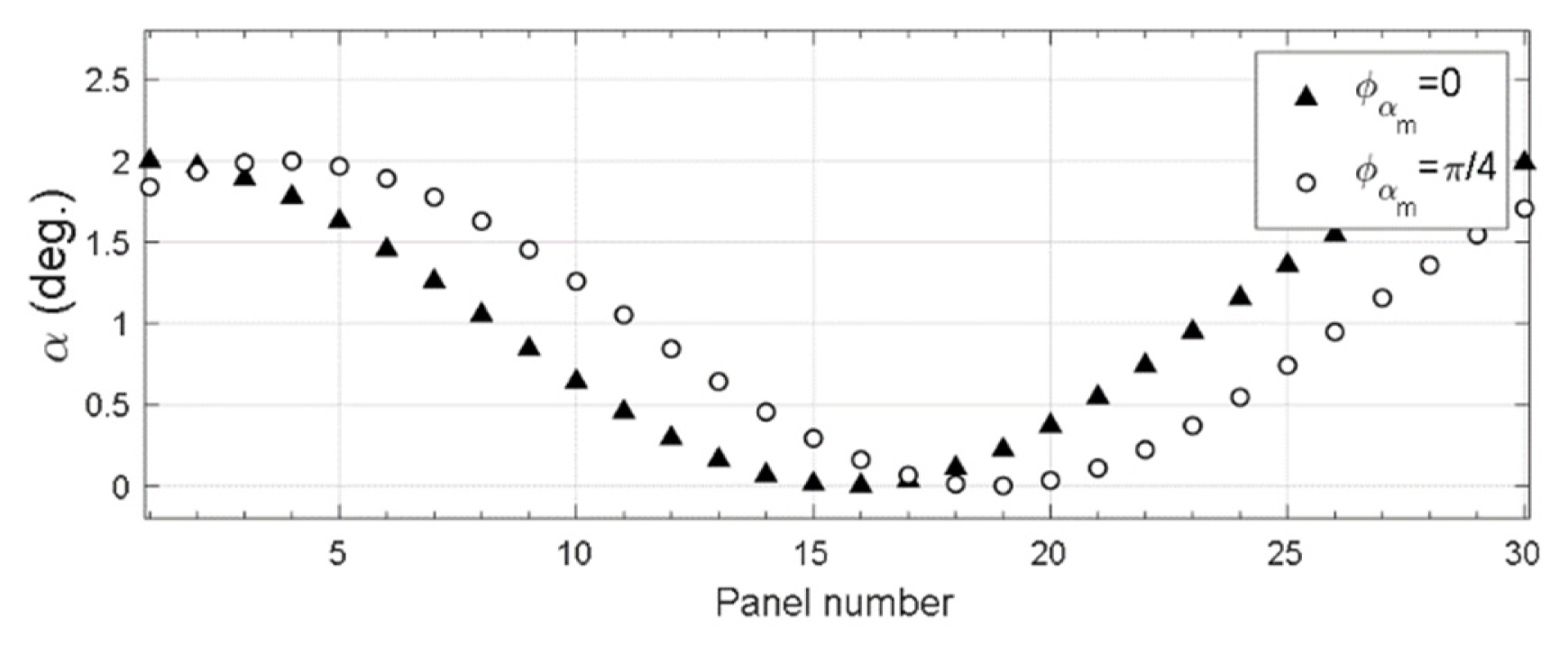
α for 1-cycle misalignment errors.
From (7), we note that ACX is positive in the 1st and 3rd quadrants, while it is negative in the 2nd and 4th quadrants, regardless of whether the misalignments are uniform or not. Fig. 6(a) shows the ACX distribution for 1-cycle misalignment with φαm=0. Since
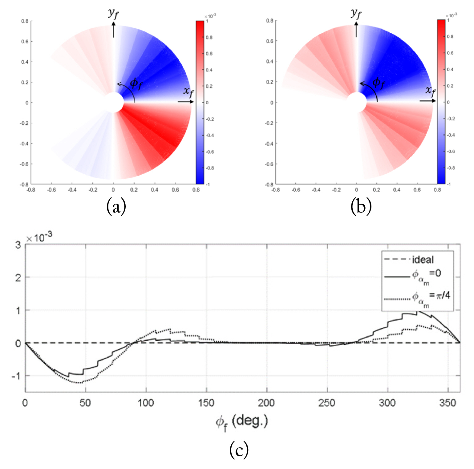
Distribution of ACX in the aperture for 1-cycle misalignment errors when αm is 2° for (a) φαm =0, (b)
Cross-pol radiation patterns for 1-cycle misalignment errors of panels in the
Since the level of cross-pol radiation depends on the net amount of ACX in the aperture, the average aperture cross-pol for a balanced feeder pattern may be expressed as:
Here, FA refers to the integration of the cross-pol component divided by an incident field from the feeder. From FA, we can easily estimate the level of cross-pol radiation for various configurations of the misalignment error. Since FA= 0 for the uniform misalignment error, the cross-pol level is very low. For a 1-cycle misalignment error with a cosine variation, FA = 0 when φαm=0, although FA≠ 0 and the cross-pol level increases when φαm≠0.
Moreover, for 1-cycle misalignments, a closed-form expression of FA can be obtained from α in (8). A smooth change in the misalignment angle is assumed and φf is used instead of φk. By implementing Taylor’s series, Pt2 is expanded into two terms, expressed as follows:
Substituting (10) in (9), FA for a 1-cycle misalignment error with a maximum misalignment angle of αm at φαm is expressed as:
Fig. 8(a) shows the calculated FA with respect to the change in φαm when αm is 2° and 4°. It is observed that FA changes along with φαm, reaching its maximum value when

Comparison with respect to φαm for 1-cycle misalignment errors of (a) FA and (b) XPOL.
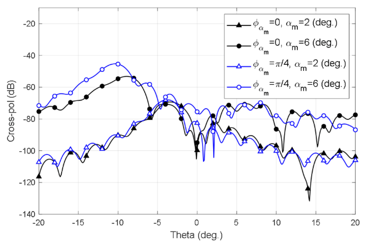
Fig. 9 depicts the cross-pol patterns in the

Cross-pol radiation patterns for 1-cycle misalignment errors of panels in the
In Fig. 10, cross-pol patterns calculated by the AXPF method are compared with the results of physical optics approximation using the commercial GRASP program for one-cycle non-uniform errors. In the case of the unbalanced Gaussian feeder, in which the ratio of the standard deviations of CH and CE is v, the cross-pol patterns of the two methods show good agreement. The agreement between the results from the two methods in the unbalanced case implies that our analysis is valid for calculating cross-pol. In the balanced case, however, the level of cross-pol radiation is very low compared to that in the unbalanced case. Moreover, the patterns do not exhibit good agreement. The results of deploying the AXPF method clearly indicate tilting of the radiation field due to non-uniform panel misalignment. Apart from this, the AXPF analysis also provides adequate results with regard to the level of cross-pol radiation resulting from panel misalignments. Additionally, it demonstrates the physical implications for the generation of cross-pol components from panel misalignments.

Comparisons of cross-pol patterns by GRASP using our method for analyzing the 1-cycle misalignment errors of panels in the
2.2. 2-Cycle non-uniform misalignments
For N = 2, αk varies across two cycles with regard to the change in φk from 0 to 2π, as shown in Fig. 11. When φαm= 0, the misalignment error reaches its maximum value at the 1st and 16th panels, and a minimum value at the 8th and 23rd panels. The configuration of the misalignment error is symmetric about the x- and y-axes. Meanwhile, the radiation patterns are symmetric, but vary in tandem with different angles of the observation planes. For
α for 2-cycle misalignment errors.
The distribution of ACX in the aperture on the occurrence of a 2-cycle non-uniform misalignment is elaborated in Fig. 12(a) and 12(b), where αm is 2°. These distributions are observed to be point symmetric about the center. For φαm=0, the net amount of ACX is zero, while the cross-pol radiation is very small. However, for
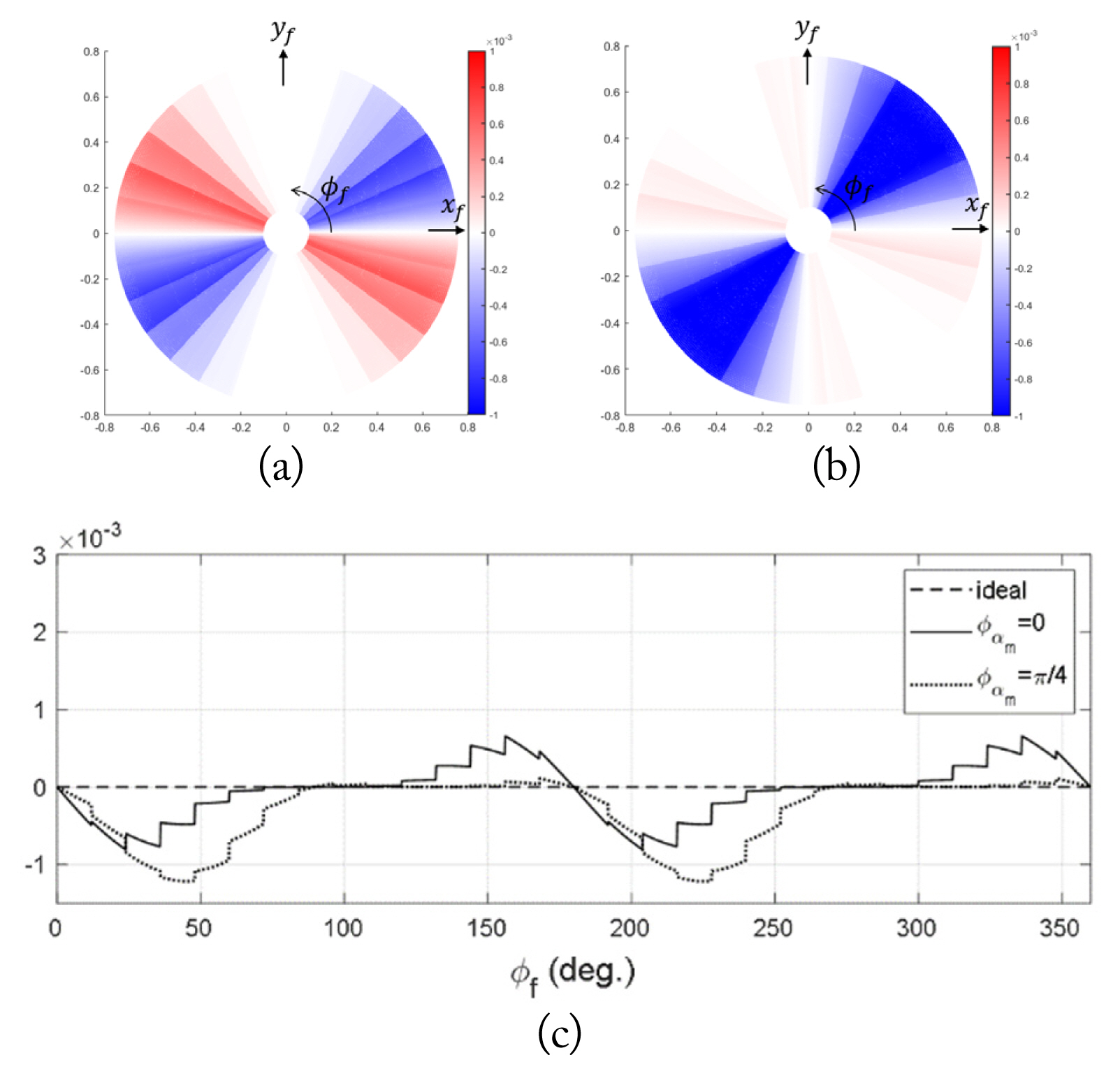
Distribution of ACX in the aperture for 2-cycle misalignment errors when αm is 2° for (a) φαm =0, (b)
For the 2-cycle panel misalignment error (N = 2), we obtained the expression of the factor of the average cross-pol in the aperture FA using (8) and (10).
Fig. 13(a) illustrates changes in FA with φαm for N = 2, with FA reaching its maximum value when
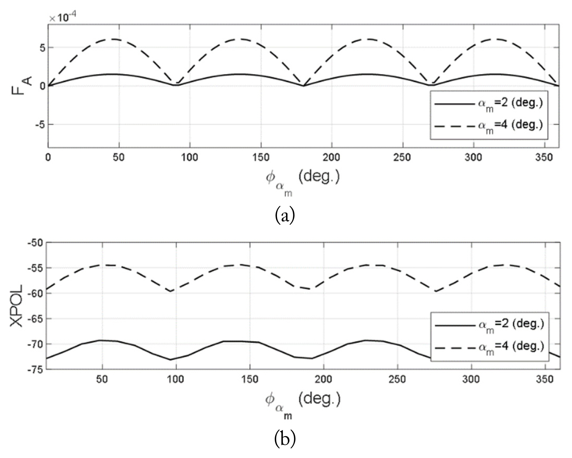
Comparison with respect to φαm for 2-cycle misalignment errors of (a) FA and (b) XPOL.
Fig. 14 shows the cross-pol patterns in the
Cross-pol radiation patterns for 2-cycle misalignment errors of panels in the
IV. Conclusion
This study first assumed the shape of the panel misalignment error that can occur in a deployable reflector antenna and then analyzed the generation mechanism of the cross-pol radiation caused by the panel misalignment error. The aperture field was calculated by considering the phase error of the signal and the rotation of the normal vector on the reflective surface resulting from the misalignment of the panel. The rotation of the normal vector caused by misalignment is an essential factor in the analysis of cross-pol performance. Moreover, the net amount of the cross-pol component in the aperture was found to be closely related to the level of cross-pol radiation. For non-uniform misalignment, the cross-pol radiation was higher, and the maximum cross-pol level was generated when
Acknowledgments
This work has been supported by the National Research Foundation of Korea (NRF) grant funded by the Korean government (MSIT) (No. 2020R1F1A107675512).
Appendices
Appendix A. Derivation of the formula for the electric field distribution at the aperture with panel misalignment
Eq. (3) in Section II indicates the electric field distribution at the aperture. By substituting (1) and (2) into Er = 2(
The aperture field expressed in the spherical coordinates is transformed into one in the cartesian coordinates and expressed as follows:
Finally, the formula for the electric field distribution in the aperture is derived by simplifying (A.2) in the (x,y,z) coordinates depicted in Fig. 1(a) as:
References
Biography

Si-A Lee received her B.S. and M.S. degrees in electronics and information engineering from Korea Aerospace University, Goyang, Korea, in 2019 and 2021, respectively. She is currently a junior researcher at Satellite System Team 1 in Hanwha Systems. Her current research interests include satellite communication antennas and radar antenna design and analysis.

Seung-Joo Jo received her B.S. and M.S. degrees in electronics and information engineering from Korea Aerospace University, Goyang, Korea, in 2018 and 2020, respectively. She is currently a junior researcher at Satellite System Team 1 in Hanwha Systems. Her current research interests include satellite communication antennas and radar antenna design and analysis.

Suk-Jin Kim received his B.S. and M.S. degrees in electronics and information engineering from Korea Aerospace University, Goyang, Korea, in 2020 and 2022, respectively. His current research interests include satellite communications and radar antennas, spaceborne SAR systems, and antenna design and analysis.

Taek-Kyung Lee received his B.S. degree in electronic engineering from Korea University, Seoul, Korea, in 1983, and his M.S. and Ph.D. degrees in electrical engineering from the Korea Advanced Institute of Science and Technology (KAIST), Daejeon, Korea, in 1985 and 1990, respectively. From 1990 to 1991, he was a postdoctoral fellow at the University of Texas at Austin, TX, USA, under a grant from the Korea Science and Engineering Foundation. From 1991 to 1992, he was a research scientist at KAIST. In 1992, he joined the faculty of Korea Aerospace University (KAU), Goyang, Korea. He was an associate visiting research professor at the University of Illinois at Urbana–Champaign, IL, USA, from 2001 to 2002. From 2006 to 2007, he was the chairman of the School of Electronics, Information, and Computer Engineering at KAU, where he also held the position of director of the Aerospace and Aviation Electronics Research Center from 2011 to 2013. He was the chairman of the Radar Technical Group, Korean Institute of Electromagnetic Engineering and Science, Seoul, from 2012 to 2013, and served as the president of this institute in 2014. He is currently a professor at the School of Electronics and Information Engineering at KAU. His current research interests include computational electromagnetics, antennas, microwave passive circuits, satellite antennas, spaceborne SAR systems, and air surveillance systems.

Jae Wook Lee received his B.S. degree in electronic engineering from Hanyang University, Seoul, Korea, in 1992, and his M.S. and Ph.D. degrees in electrical engineering with a specialization in electromagnetics from the Korea Advanced Institute of Science and Technology, Daejeon, Korea, in 1994 and 1998, respectively. From 1998 to 2004, he was a senior member of the Advanced Radio Technology Department, Radio and Broadcasting Research Laboratory, Electronics and Telecommunications Research Institute, Daejeon. Additionally, he has been on the faculty of Korea Aerospace University (KAU), Goyang, Korea. He is currently a professor at the School of Electronics and Information Engineering at KAU. His current research interests include high power amplifier design, computational electromagnetics, electromagnetic interference and electromagnetic compatibility analysis on printed circuit boards, satellite antennas, and spaceborne SAR systems.