I. Introduction
Monopulse antenna arrays are generally applied to target-tracking in radar systems for the accurate angle estimation. Conventional monopulse antennas that use horns, lenses, and Cassegrain parabolic antennas are bulky and heavy. For these reasons, microstrip structures with low profiles and light weights are widely used. However, the microstrip monopulse antenna has disadvantages in terms of larger radiation loss and spurious radiation in the millimeter-wave band [1, 2]. Recently, substrate-integrated waveguide (SIW) technology has been applied to monopulse antennas due to its low loss, low cost, and ease of integration [3, 4]. Various SIW technology-based monopulse antennas have been reported: SIW monopulse antenna arrays with microstrip feed [3], SIW monopulse slot antenna arrays with magic-T junction [4], monopulse antenna arrays based on a dual-mode SIW cavity [5, 6], SIW-slot array monopulse antenna in a planar single-substrate structure [5], and SIW-filtering monopulse slot antenna array using diagonal internal coupling slots in a double-substrate structure [6].
In addition, the filtering antenna (filtenna) provides the rejection of unwanted interferences, enhancing the system linearity.
This paper proposes a millimeter-wave monopulse filtenna array using DRs with higher-order mode excitation and SIW technology with a planar single-substrate structure. The design procedure of the proposed monopulse filtenna array is as follows: First, the DR antenna with HEM133 mode and a SIW feeding structure with a circular aperture was designed. Second, the 4th-order Chebyshev SIW filter was realized. Third, a single SIW-DR filtenna was produced by combining the DR antenna and the SIW filter. Fourth, a monopulse comparator was designed using the dual-mode SIW cavity and diagonal irises. Finally, the monopulse filtenna array was implemented with both SIWŌĆōDR filtennas and the monopulse comparator.
II. Monopulse Filtenna Array Design
A designed dielectric resonator antenna (DRA) using a cylindrical DR with the electrical properties of ╔ør = 9 and tan╬┤ = 0.0005 is fed by a circular aperture on the top layer of a SIW, which was implemented by the substrate with ╔ør = 2.2, tan╬┤ = 0.0009, and T = 0.508 mm. The DRA using higher-order mode excitation, such as HEM133 for millimeter-wave band is advantageous due to its low conduction loss [7] and enhanced directivity [8]. It has the disadvantage of a relatively narrow impedance bandwidth (BW) [9].
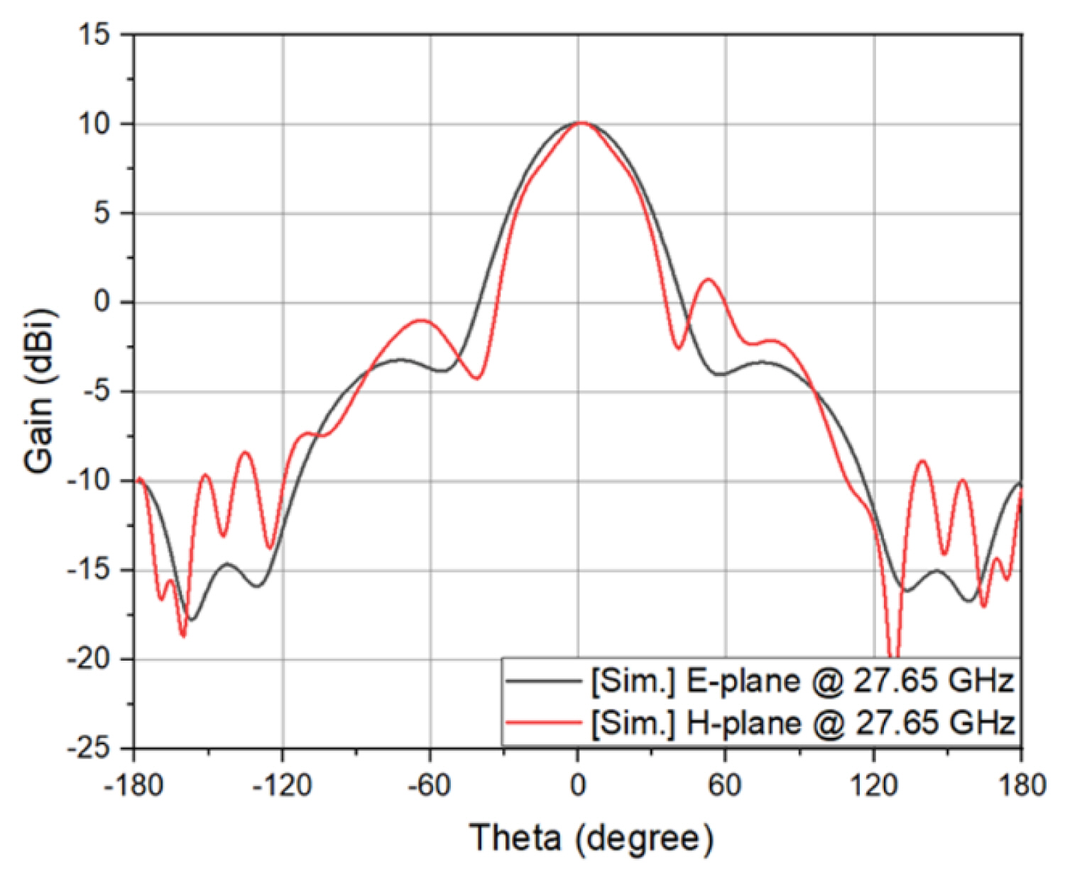
The initial dimensions of the DR with HEM133 mode were estimated by the magnetic wall method using commercially available software such as a CST Eigenmode Solver with a simple SIW feeding network including the aperture [9]. The aperture is employed to have a lower back lobe level than the microstrip line for antenna feed structures [8], satisfying internal coupling and external quality factor for the requirement of the designed filtenna. Fig. 1 illustrates the simulated H-field distributions of the desired HEM133 mode of the DR. The initial diameter of the coupling aperture and its distance from the shorted end of the SIW are based on [8]. The dimensions of the resonator and aperture were optimized for maximum directivity at the center frequency of 27.65 GHz. The SIW is fed by a grounded coplanar waveguide (GCPW) line adjoined to the SIW. The GCPW line, including two linearly tapered slots, was optimized for improving the return loss performance of the DRA. The width of the SIW feeding network acting as TE101 and TE102 cavities was determined for the required speculation of the filtenna. Fig. 2 depicts the simulated radiation patterns of the designed single DRA for the E- and H-planes. The DRA provides a return loss of greater than 20 dB and gains of 10.1 dBi for the E- and H-planes at the center frequency of 27.65 GHz, respectively.
1. Design of 4th-order Chebyshev SIW Filter
To design the SIW filter, the lowpass filter prototype coefficients (gi) should be calculated first. From those parameters, the external quality factor (Qe) and coupling coefficients (kij) for the filter can be determined as
where FBW is the fractional bandwidth.
The design parameters of the SIW filter for a 4th-order Chebyshev response with a center frequency of 27.65 GHz, a BW of 700 MHz, and a return loss of better than 15 dB can be obtained as Qe = 47.35, k12 = 0.0203, k23 = 0.0163, k34 = 0.0203. Then, the generalized coupling matrix of the filter is given by:
The fundamental size of the TEm0p mode for a rectangular SIW cavity can be obtained by the following formula [10]:
where
Here, w and l are the width and length of the cavity, respectively; d and p are the diameter of metallized via holes and the center-to-center distance between adjacent via holes, respectively; c0 is the phase velocity in free space; and ╔ør is the relative dielectric constant of the substrate.
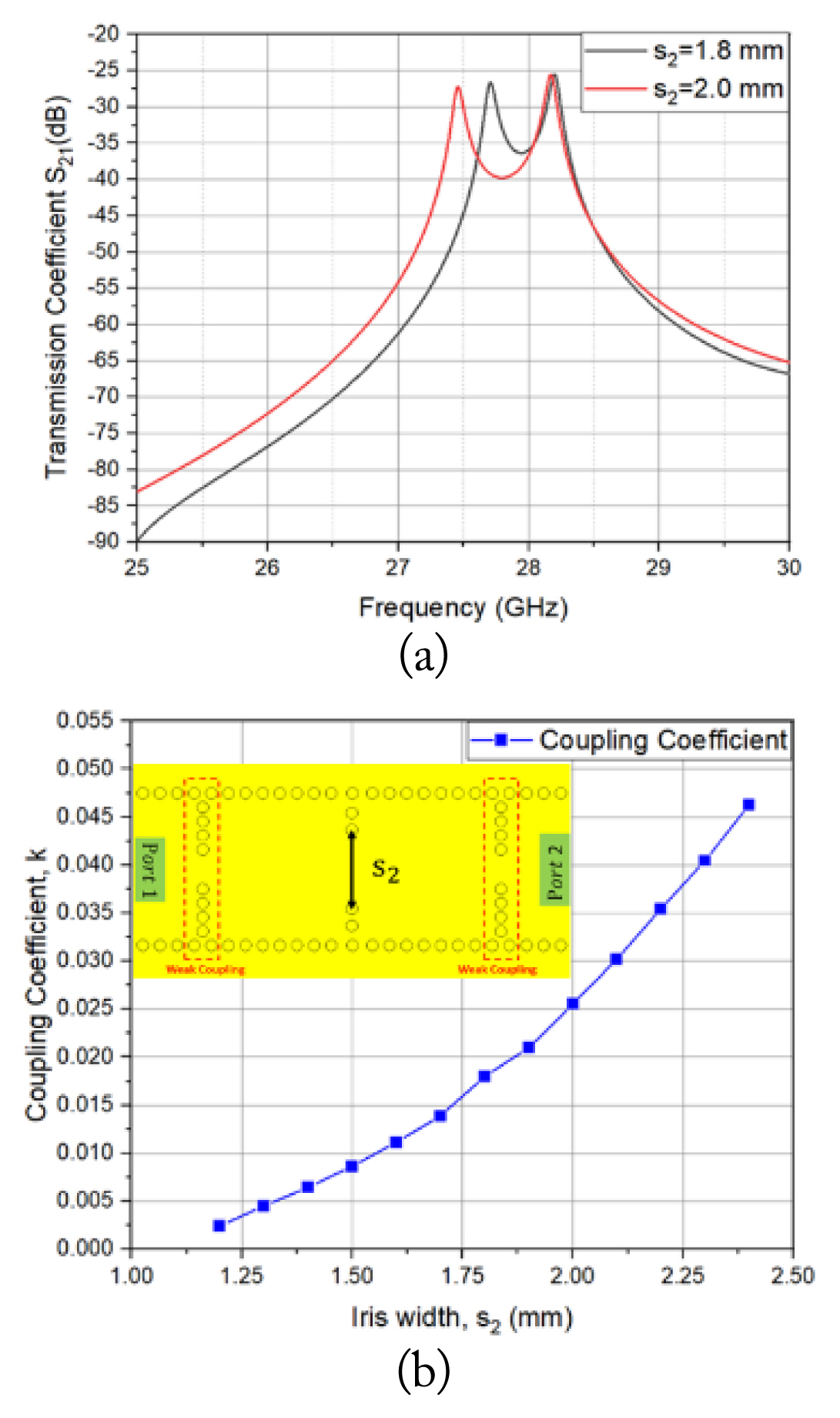
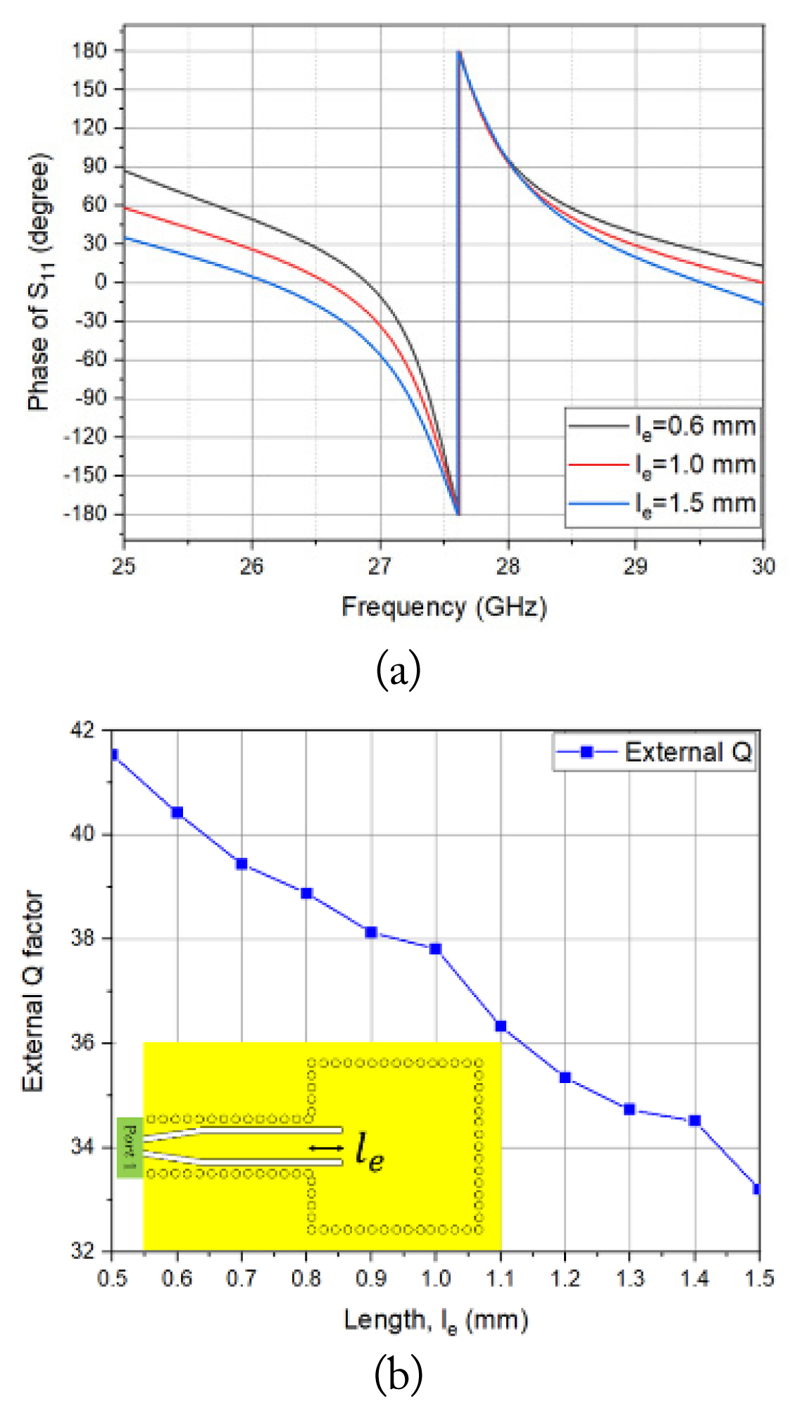
Fig. 3 illustrates the simulated frequency response of the phase of S1 and extracted external quality factor in the TE101 SIW cavity. Fig. 4 depicts the simulated frequency response of the transmission coefficient and extracted internal coupling coefficient against the inductive iris width between both TE101 SIW cavities. The coupling coefficients can be obtained using the following relation [11]:
where f2 and f1 are the high and low resonant frequencies, respectively, and k is the coupling coefficient between adjacent SIW rectangular cavities.
The external quality factor for the GCPW-to-SIW transition can be determined by the equation [11]:
where f0 and ╬öfŌłÆ90┬░ to +90┬░ are the center frequency and BW of S1, respectively, and the BW is defined by the phase of S1 changing from ŌłÆ90┬░ to +90┬░.
The obtained design parameters were used for the initial design of the 4th-order Chebyshev SIW filter and optimized for the desired specification. Fig. 5 shows the simulated frequency responses of the return and insertion losses of the filter. The designed filter has a center frequency of 27.65 GHz, a BW of 700 MHz, a return loss of better than 15 dB, and a minimum passband insertion loss of 1.88 dB.
2. Design of 4th-order Chebyshev SIW Single Filtenna with DR
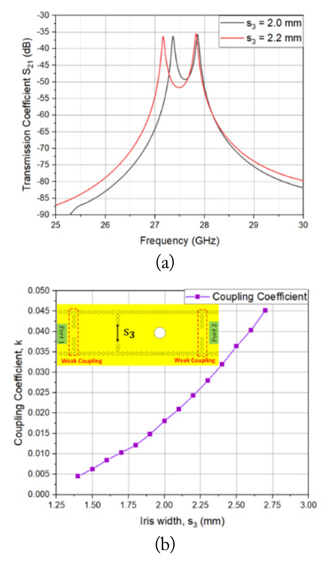
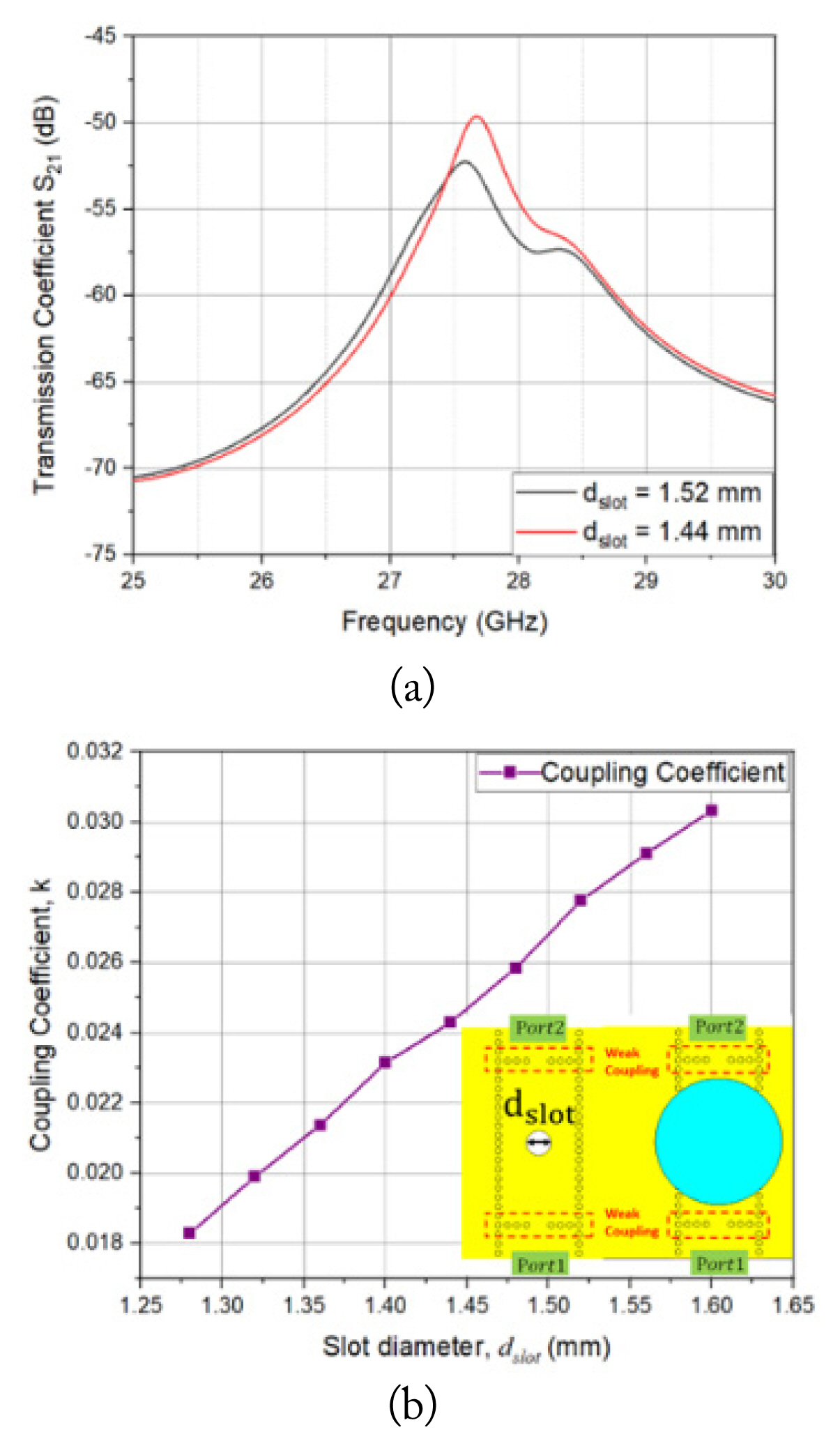
The filtenna multifunctionally provides both filtering and radiating in a single unit, reducing the size and cost [12, 13]. The filter specification of the single SIW filtenna is identical to that of the 4th-order Chebyshev SIW filter. The design parameters and generalized coupling matrix of the single SIW filtenna were obtained using the same procedure as the SIW filter. As depicted in Fig. 4, the internal coupling coefficient between the first and second SIW cavities can be extracted. The circular aperture is employed to satisfy the requirement of the internal coupling between the third and fourth resonators and the external quality factor of the radiator for the desired BW and return loss of the filtenna. A relatively large circular aperture away from the shorted end of the SIW compared to ╬╗g/4 length is employed for the required internal coupling and external quality factor of the filtenna. Therefore, the TE102 cavity is introduced as the third SIW cavity in addition to the second SIW cavity operating at TE101 mode. The DR acts as the fourth resonator and the radiator in the filtenna [14]. Fig. 6 displays the simulated frequency response of the transmission coefficient and the extracted internal coupling coefficient between the TE101 and TE102 SIW cavities with straight inductive iris. Fig. 7 shows the simulated frequency response of the transmission coefficient and extracted internal coupling coefficient between the TE102 SIW cavity and DR with circular aperture. The coupling coefficients can be obtained by the Eq. (4).
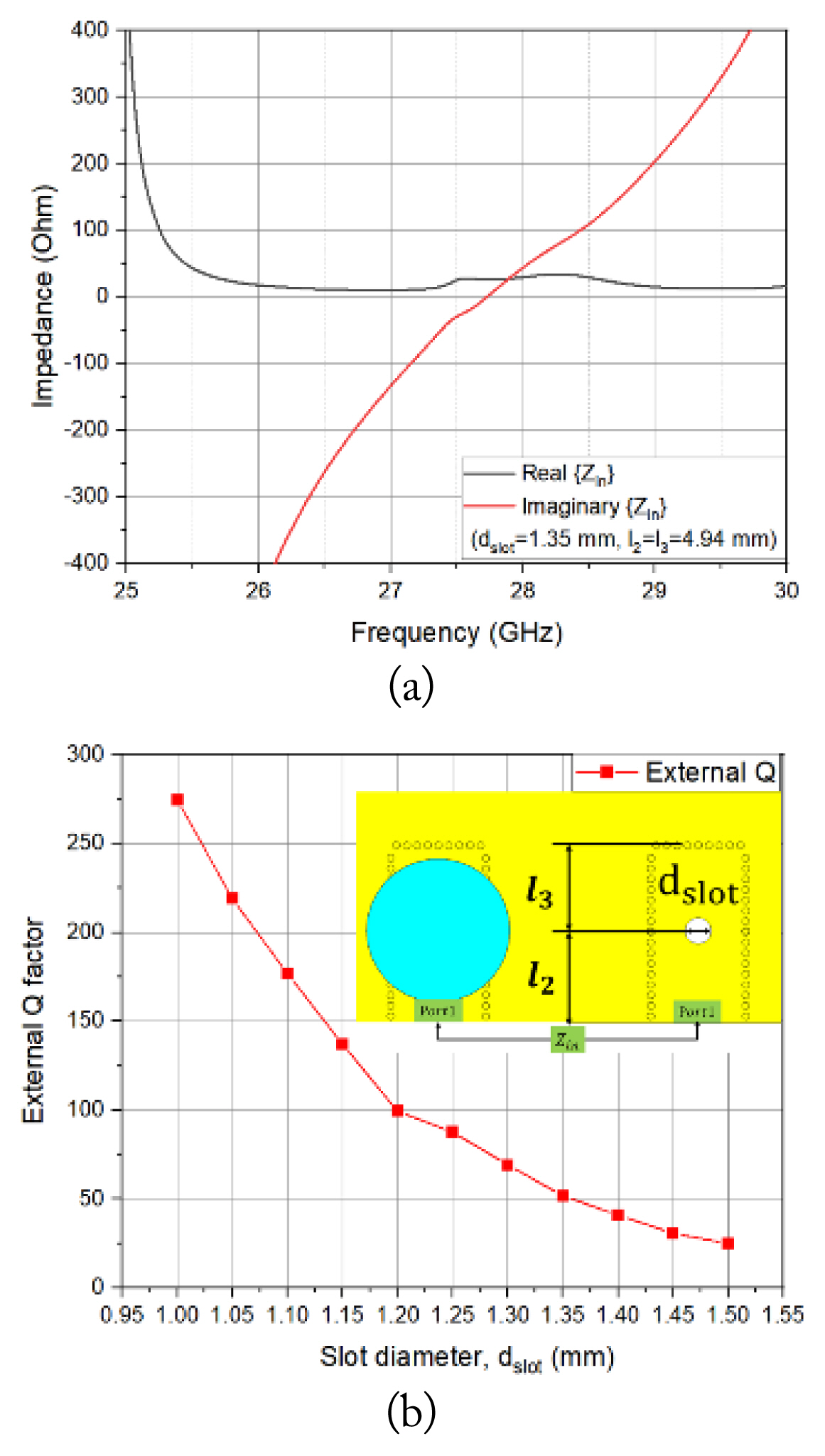
Fig. 8 depicts the simulated frequency response of the input impedance, Zin of the TE102 mode cavity with the circular aperture and DR and extracted external quality factor against the diameter of the circular aperture. The external quality factor can be calculated by the following formula [15]:
where fo is the resonant frequency.
The length of the TE102 mode cavity and diameter of the circular aperture were modified, and the external quality factor was extracted for each cavity with a resonant frequency of 27.65 GHz.
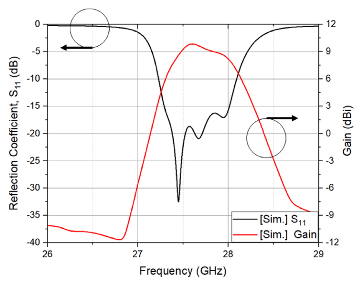
The extracted design parameters were applied to the initial design of the 4th-order Chebyshev SIW-DR filtenna and optimized for the desired specification. Fig. 9 depicts the simulated reflection coefficient and antenna gain. Fig. 10 illustrates the radiation patterns for the E- and H-planes. The designed DR filtenna at the center frequency of 27.65 GHz offers a BW of 700 MHz, return loss of greater than 15 dB, and gain of 9.7 dBi.
3. Design of the Monopulse Filtenna Array
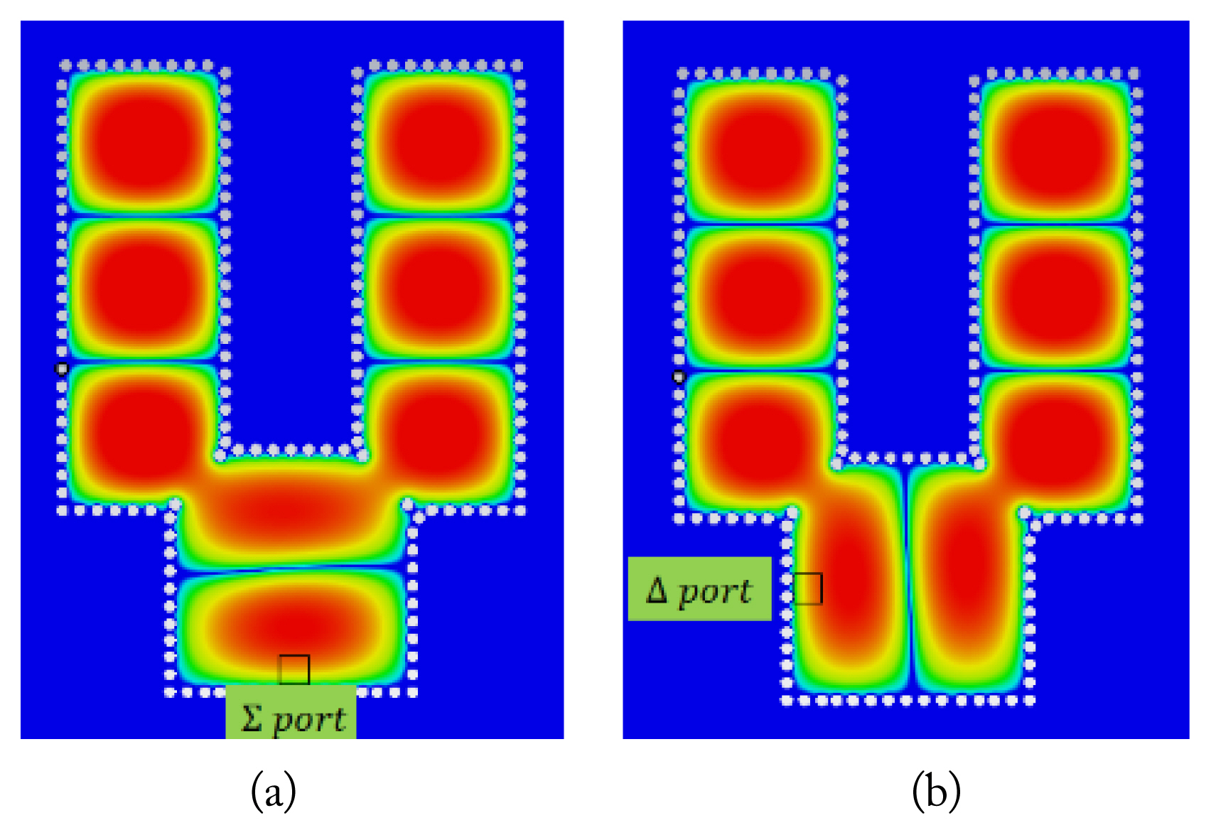
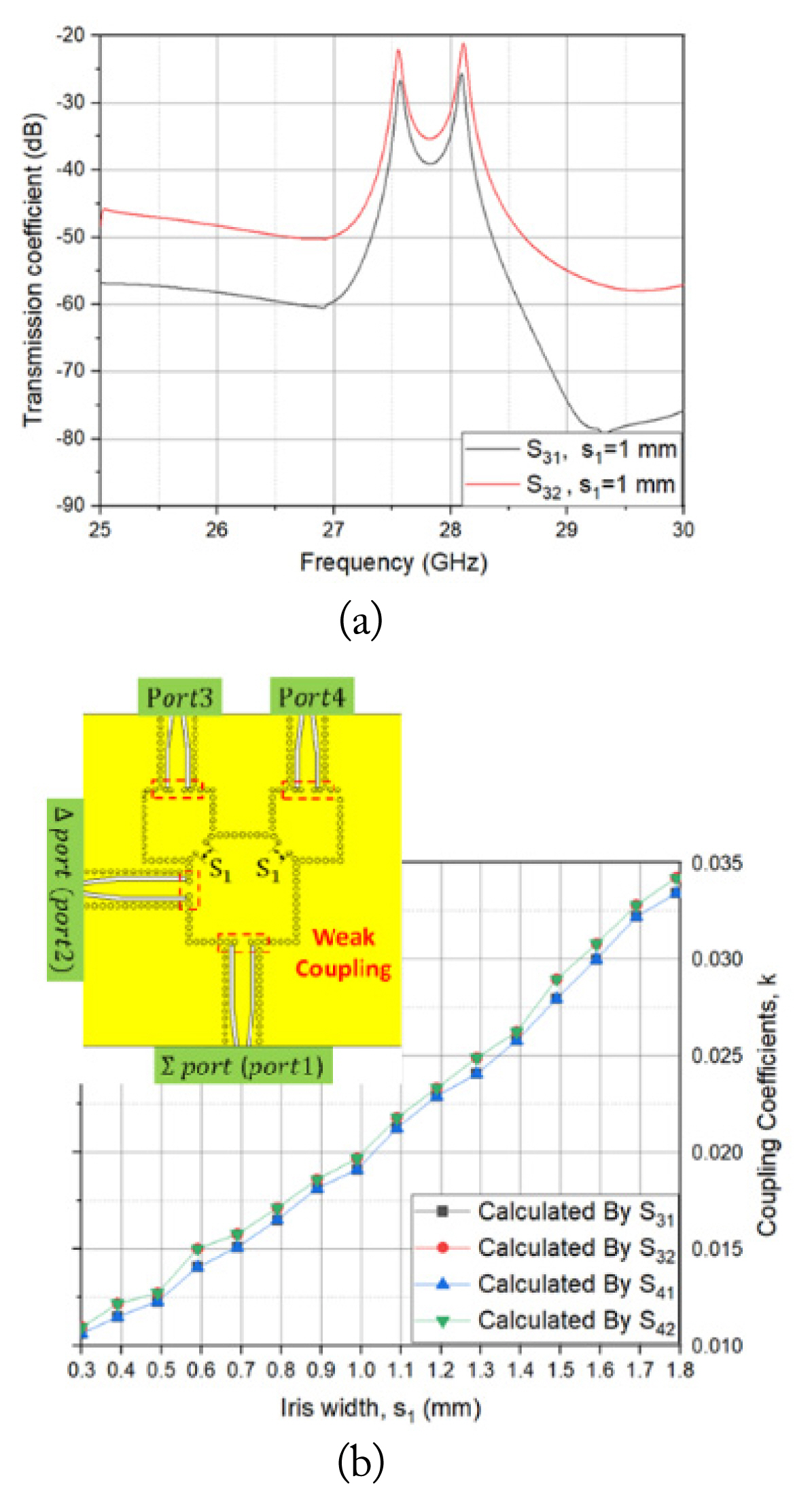
The proposed monopulse filtenna array includes a monopulse comparator, SIW cavities with circular apertures, and both DRs. The monopulse comparator realized by a square dual mode for the sum and difference ports operates at TE102 and TE201 modes, respectively, and the second and third work at TE101 and TE102 modes, respectively. The designed filtenna has 4th-order Chebyshev response, including the first-stage resonator of the monopulse comparator and the other resonators of the other two cavities and the DR. Fig. 11 shows the electric field (E-field) distributions on the top surface of the DR filtenna for the sum and difference channels at the frequency of 27.65 GHz. As can be seen, the SIW dual-mode cavity operates in both degenerated modes of TE102 and TE201 with the orthogonal property at the frequency of 27.65 GHz, and thus the feed cavity shows acceptable isolation characteristics. The internal couplings between the feed and second cavities for both sum and difference channels affect the filter responses of the BWs and return losses for both channels. In this paper, a diagonal iris geometry between the monopulse comparator with TE102 and TE201 modes and next-stage cavities with TE101 modes has been proposed. The diagonal iris configuration leads to almost identical internal couplings for both sum and difference channels, and thus the filtering responses of the BWs and return losses for both channels are almost identical to each other, while maintaining a planar single-substrate structure with a compact size.
Fig. 12 illustrates the simulated frequency response of the phase of S1 and extracted external quality factor calculated from the Eq. (5). With respect to the width of the inductive iris window s1(=s2), the external coupling coefficients calculated from the Eq. (4) are shown in Fig. 13. The extracted design parameters were applied to the initial design of the 4th-order Chebyshev SIW-DR filtenna array and optimized for the desired specification.
III. Simulation and Measurement
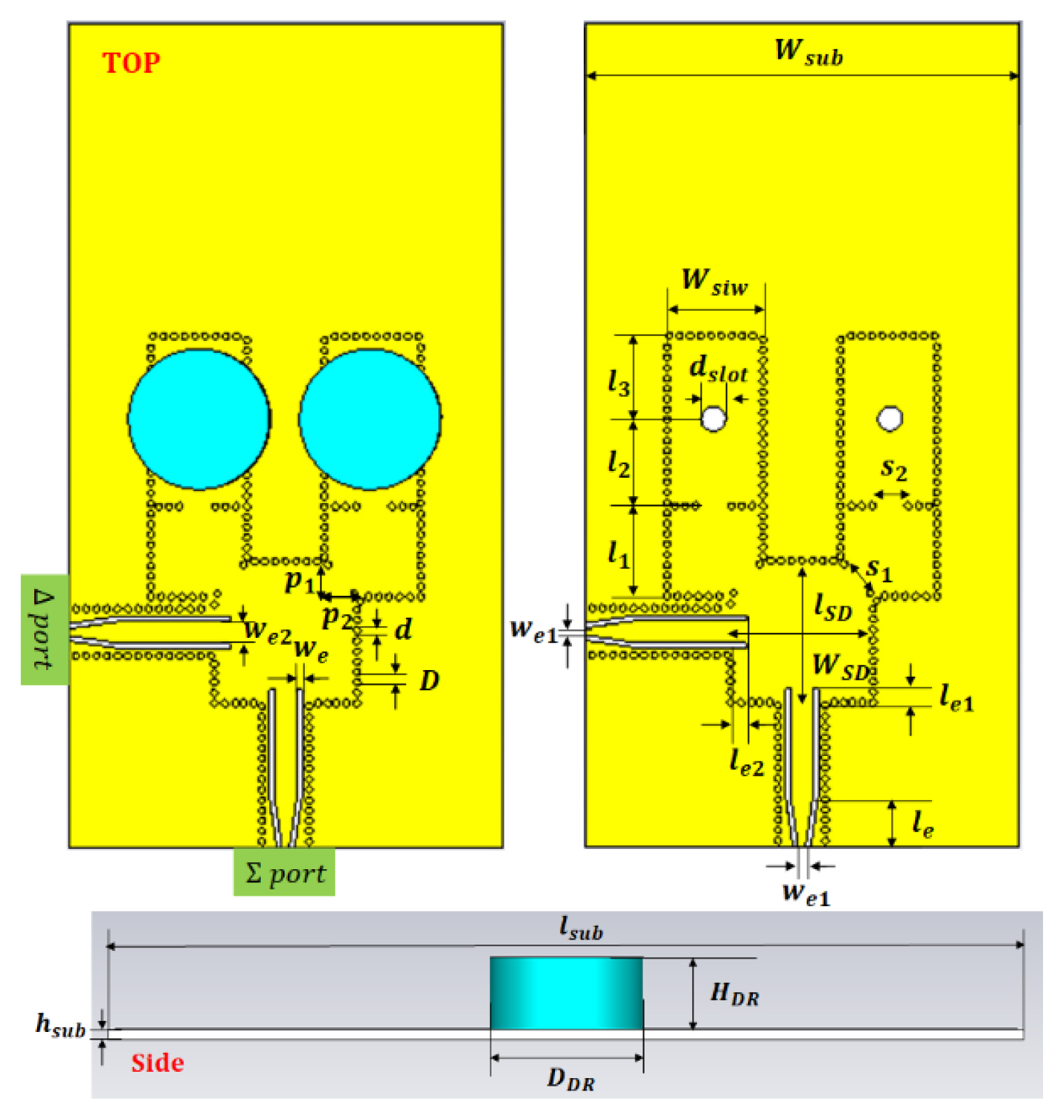
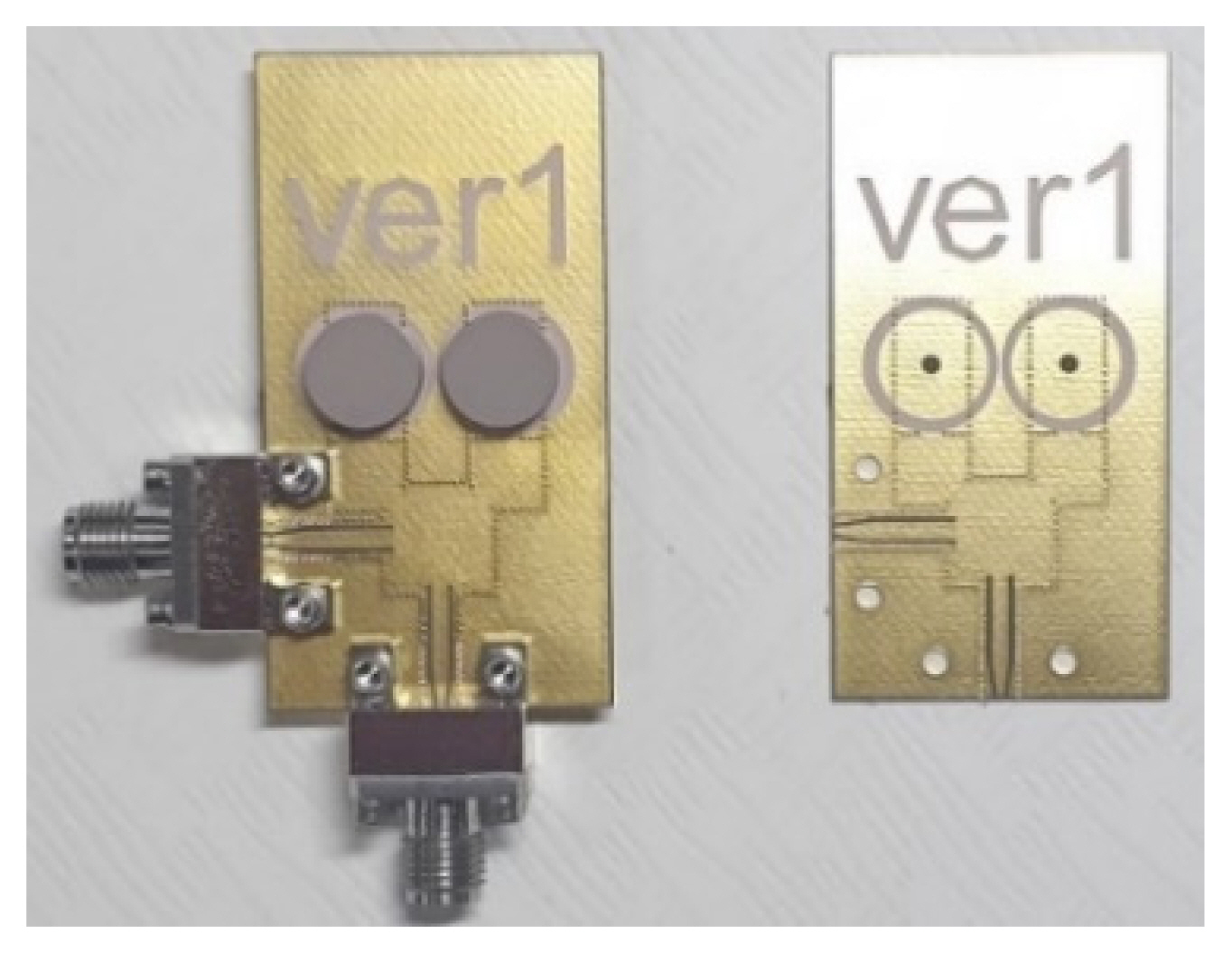
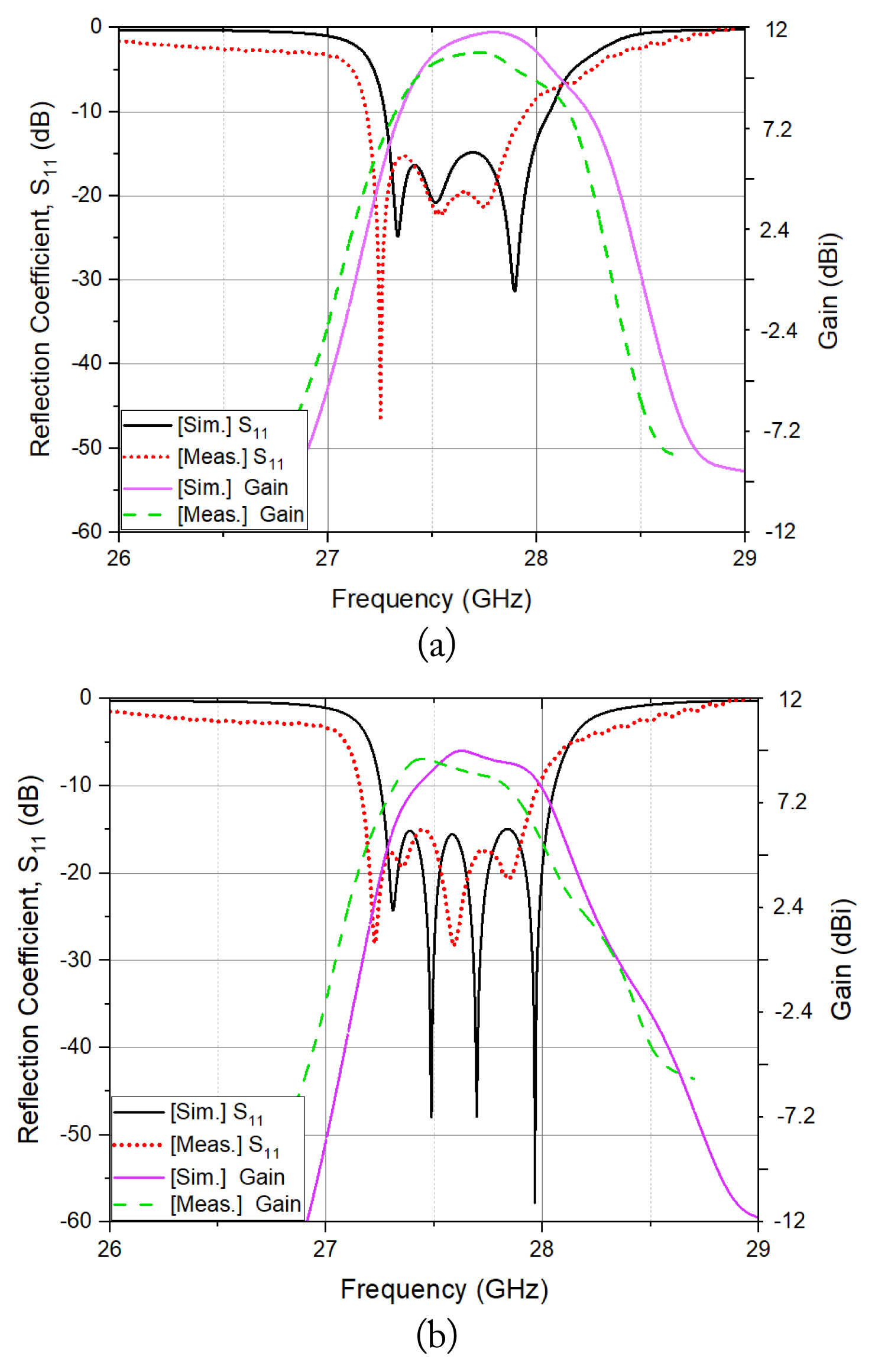
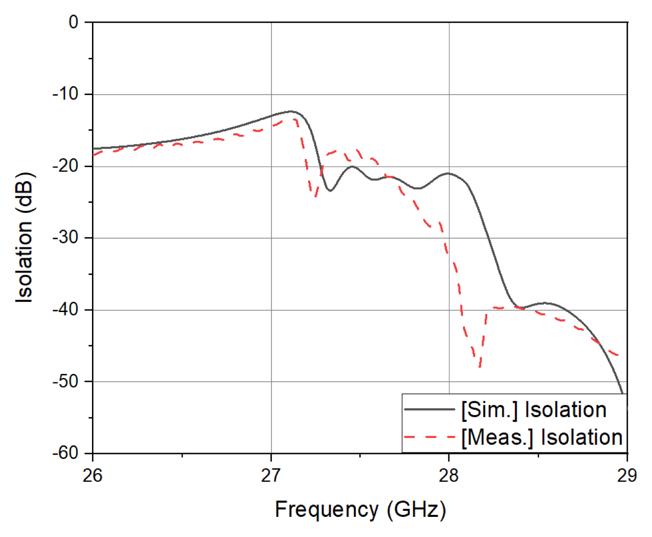
Fig. 14 shows the configuration of the designed monopulse filtenna array, of which the dimensions are listed in Table 1. Fig. 15 depicts the photograph of the fabricated monopulse DR filtenna array. In the simulation and measurement, the return losses, isolation, and gains of the proposed monopulse DR filtenna array are illustrated in Figs. 16 and 17. The designed DR filtenna provides 15-dB fractional bandwidths of 2.36% and 2.7%, a passband isolation of greater than 17.7 dB, gains of 10.84 and 8.50 dBi for the sum and difference channels, respectively, and a difference beam null depth of ŌłÆ15.6 dB at a frequency of 27.65 GHz. The performance summary of the published SIW-based monopulse antenna arrays are tabulated in Table 2 [4, 5, 6, 16, 17, 18].
In the simulation and measurement, the radiation patterns of the proposed DR filtenna at 27.65 GHz are depicted in Fig. 18.
The measured filtering responses and antenna gains for the sum and difference channels agree well with the simulated responses in terms of tendency. The measured antenna gains for the sum and difference channels were smaller than the simulated antenna gains by 0.86 and 0.92 dB, respectively. The total efficiencies of the DR filtenna array for the sum and difference channels were calculated using the simulated directivities and measured gains and achieved as 62% and 64% for both channels, respectively, at a frequency of 27.65 GHz. The discrepancies in filtering responses, antenna gains, and total efficiencies between simulation and measurement are primarily caused by the insertion loss of the fabricated filter and manufacture tolerance of the PCB fabrication process. The null depth for the different beam patterns was adversely affected by the body of the K connector located close to one of both DRs (Fig. 15).
IV. Conclusion
This paper proposes a new SIW-DR monopulse filtenna array in the Ka-band. The size of the entire circuit is reduced by virtue of filtenna structure. The filtenna has a 4th-order Chebyshev filter response, and the DRA adopting higher-order mode excitation with HEM13 results in enhanced directivity. The diagonal internal coupling irises between the feed dual-mode and next-stage SIW cavities contribute to maintaining a planar single-substrate with compact size. The proposed SIW-DR monopulse filtenna array are expected to be applied to practical millimeter-wave designs by virtue of its high directivity, low loss, low cost, compact size, and fabrication with a planar single-substrate structure.