Leakage Power Canceling Module with a Negative Capacitor for a Circulator’s Isolation
Article information
Abstract
In this study, we developed a leakage power canceling module (LPCM) incorporating a negative capacitor (NCAP). The NCAP provided the circulator with a wide bandwidth, rendering it suitable for retrodirective short-range wireless power transfer applications. The proposed LPCM consisted of a directional coupler, a hybrid coupler, and a low-pass filter network with an NCAP that exhibited the frequency response required to realize leakage power cancellation from the transmitter output to the receiver input. The two couplers were fabricated in an FR4 printed circuit board, and the NCAP was implemented using Samsung LR6LP 65 nm RF CMOS IC technology. The NCAP chip provided a capacitance of −2 pF and consumed a DC voltage and current of 3 V and 13 mA, respectively. The size of the fabricated LPCM was 41 mm × 37 mm. The application of the proposed LPCM was demonstrated with a commercial circulator. The S-parameter measurements indicated that the leakage cancellation was 20–46 dB at a frequency range of 2.29–2.515 GHz. The bandwidth was defined considering a leakage cancellation of more than 20 dB, and the actual and fractional bandwidths were 222 MHz and 9.25%, respectively.
I. Introduction
Short-range indoor wireless power transfer (WPT) applications have recently garnered interest [1]. Moreover, retrodirective arrays (RDAs) have been considered promising candidates for beamforming because of their compactness and cost effectiveness. A key component of the RF system for RDAs is a circulator. However, the isolation characteristic of the circulator between the transmitter (TX) output and the receiver (RX) input affects the performance of the array system. The power leak from the TX to the RX reduces sensitivity and degrades the beamforming accuracy of the system [2].
Many researchers have attempted to enhance the circulator’s isolation characteristics by canceling the TX leakage. Conventional feedforward circulator leakage cancellers with an attenuator and a phase shifter have been widely used [3, 4]. However, this technique produces extremely narrowband characteristics. Another RF-based canceler for frequency-division duplexing/full duplex (FDD/FD) systems was discussed in [5], in which where N-path filters played adopted the role of a configurable phase shifter, which was analogous to any conventional one concerning functions. Nevertheless, this approach presents some challenges in terms of resolving the issues of poor linearity and high power consumption. In [6], a leakage power canceling module (LPCM) was developed that used a tuner with a barium strontium titanate (BST) varactor at the antenna port. By changing the impedance of the antenna port, the TX signal bounced back into the circulator and canceled the TX leakage at the RX port. However, this approach had the limitations of excessive power loss in the TX-ANT path and a high-bias voltage due to the use of Opamp. In addition, an LPCM based on digital signal processing (DSP), which exhibited satisfactory performance, was established in [7]. However, this approach requires the use of numerous devices, causing an excessively complex implementation and notable DC power consumption. Although the BST tuner and DSP-based LPCMs could provide a wider bandwidth than the conventional LPCM, the bandwidth extension was not sufficient for use in the retrodirective short-range WPT system reported in [2]. Considering these aspects, this paper reports a feedforward LPCM with an active capacitor that provides negative capacitance to increase bandwidth.
II. Analysis and Design
Fig. 1 shows a simplified diagram of the RF system with the feedforward LPCM, which we used for the RDA introduced in [2]. The frequencies of TX and RX were 2.4 GHz and 2.5 GHz, respectively. The LPCM consisted of three basic blocks: power division, power combination, and feedforward. For power division and combination, a directional coupler and a hybrid coupler were used, respectively. To mitigate the TX output power waste and to consider the inherent isolation (baseline) of the circulator, the directional coupler was designed to couple only −20 dB relative to its source. Furthermore, a low-pass filter network (LPFN) with inductors and capacitors was used when designing the feedforward block (Fig. 2(a)). We included a negative capacitor (NCAP), CN, in the LPFN to ensure the required magnitude and phase responses for TX leakage cancellation across a wide frequency range (Fig. 3). It should be noted that considering each single value pair of attenuator and phase shifter (Ri, Φi) in the feedforward block (Fig. 1) provides the best isolation between the TX and RX (e.g., 80 dB) at a single frequency (fi) in the bandwidth of interest. The value of 80 dB is only an example, as different applications require various amounts of cancellation depending on their system analysis (e.g., 20 MHz bandwidth of 20 dB cancellation for full-duplex wireless communication in [5]). In our wireless power transfer system, 50 dB (de-embedded 30 dB from the circulator) is sufficient to meet the system requirements (4.3 ps jitter in the time domain [2]). Furthermore, the best isolation at fi is attained when the amplitude and phase of the feedforward canceling signal have matching amplitudes and a 180° phase difference with the leakage signal through the circulator. As a result, by using the data item in the ADS tool, we could establish the magnitude and phase response of the feedforward path (long dashed line in Fig. 3) consisting of the entire single points (Ri, Φi) in the bandwidth between 2.3 and 2.6 GHz and consider this as the “requirement.” To emulate this “requirement” in terms of phase and magnitude, we used an LPFN with an NCAP device (CN) (Fig. 2). There was a proviso that the matching conditions for the LPFN should be satisfied at 10 dB at least to reduce the power waste from the TX path. As shown in Fig. 3(b), the near-zero phase slope of a pure NCAP (non-foster element) can manipulate the negative phase slope of the LPFN with only the conventional passive components (C1, C2, and L) to meet the “requirement.” After inserting the NCAP into the LPFN, all components were combined to construct the required phase shift and attenuation at a wide frequency range (LPFN with NCAP in Fig. 3). Fig. 2(b) shows a simplified schematic of the NCAP based on an impedance converter with positive feedback using a cross-coupled differential NMOS device pair and a load capacitor (CL). The design technique for a two-port stable NCAP, as reported in [8], was adopted with a straightforward formula for the input impedance of ≈2/gm−M1,2 +1/(−sCL). For more details on NCAP properties, please refer to [8]. The NCAP used a symmetrical single NMOS pair, and the two ports of the NCAP corresponded to the source terminals of each NMOS device. To obtain an NCAP with a value of −2 pF (at 2.45 GHz with < 5% variation from 2.2 to 2.6 GHz), the following design parameters were selected: (W/L)M1,2 = 6670, (W/L)MP1,2 = 240, (W/L)MN1,2 = 50, CL = 0.85 pF, and CD = 10 pF. The supply voltage and total current consumption were 3 V and 13 mA, respectively.

Configuration of an RF system with feedforward LPCM.
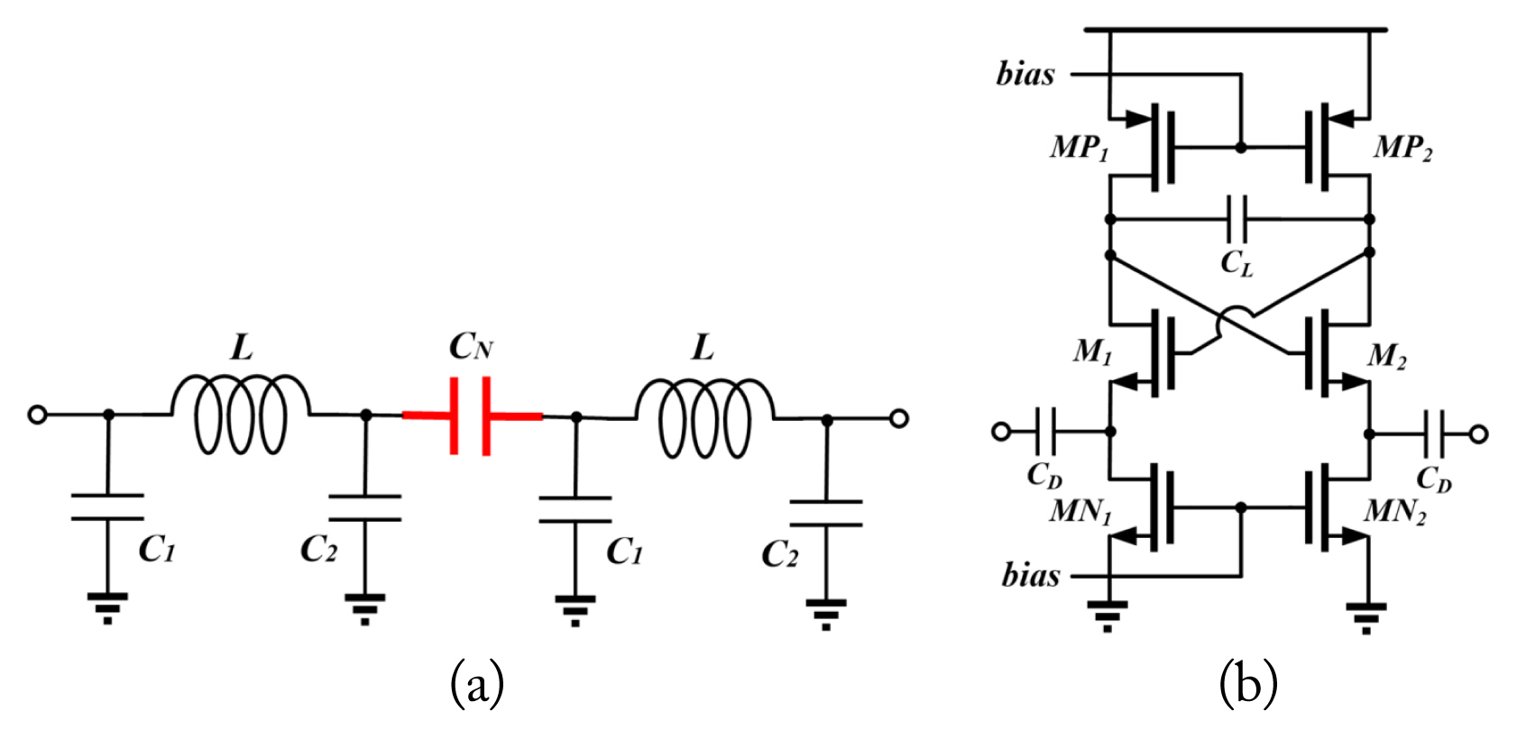
Configuration of a feedforward block of the proposed LPCM: (a) simplified circuit schematic of LPFN with NCAP and (b) simplified circuit schematic of NCAP.

Simulation results of the required frequency response for feedforward cancellation. LPFN emulates the “requirement” in terms of (a) magnitude and (b) phase.
Fig. 4 shows the simulation results of the circulator’s isolation with the proposed LPCM. The LPFN was designed to obtain the first and second best-isolation at 2.5 GHz and 2.4 GHz, respectively, because of the frequency planning of the retrodirective RF system. The aim was to improve the minimum sensitivity, mitigate the linearity requirements, and reduce the filtering burden in the RX. In Fig. 4, Sim I represents the results of the conventional feedforward LPCM, which uses an attenuator and a phase shifter only for 2.5 GHz and exhibits narrowband characteristics. This LPCM shows excellent cancellation of approximately 60 dB at 2.5 GHz but only 9 dB at 2.4 GHz. Sim II represents the results of the proposed LPCM using the LPFN with ideal passive components. The values of CN, C1, C2, and L are designed to be −2 pF, 3.1 pF, 6.9 pF, and 1.48 nH, respectively. A perfect frequency response was obtained at 2.4 GHz and 2.5 GHz, and excellent cancellation was observed at the two frequencies. Sim III represents the results obtained using the NCAP circuit. The results of Sim II and Sim III showed some discrepancies due to the lossy parasitic components in the circuit. The isolation performance at approximately 2.4 GHz shifted toward the lower frequencies and degraded.
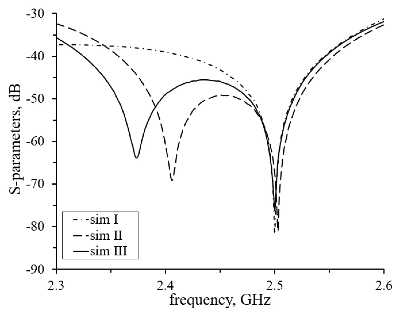
Simulation results of TX/RX isolation with the proposed LPCM (Sim I, conventional feedforward at a single frequency; Sim II, LPFN with an ideal NCAP model; and Sim III, LPFN with a real PDK NCAP circuit).
III. Implementation and Measurement
The proposed LPCM was fabricated on an FR4 printed circuit board (PCB), and the NCAP was implemented using Samsung LR6LP 65 nm RF CMOS IC technology. A photograph of the fabricated LPCM incorporating the surfacemounted device (SMD) circulator (UIYSC25A2300T2500) is presented in Fig. 5. The dimensions of the LPCM and NCAP were 41 mm × 37 mm and 624 μm × 509 μm, respectively. The chip was mounted and wire-bonded on the open-faced package with 16 leads and a size of 3 mm × 3 mm. The directional and hybrid couplers were fabricated in the PCB, and the LPFN was implemented using commercial SMD off-chips (inductor and capacitor chips) and the designed NCAP chip.
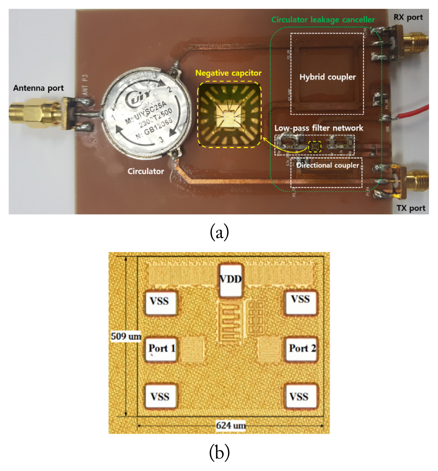
Photograph of the fabricated (a) LPCM and (b) NCAP chip.
The measured results of the isolation of the circulator with the fabricated LPCM are presented in Fig. 6. The isolation performance shifted to slightly lower frequencies compared with the simulation due to the larger number of parasitic components in real devices. The isolation characteristics at 2.5 GHz and 2.4 GHz were −57 dB and −47 dB, respectively. Excluding the intrinsic isolation of the circulator, the leakage cancellation at 2.5 GHz and 2.4 GHz was 31 dB and 24 dB, respectively, and the noise figure increased by 3.7 dB at 2.5 GHz. Therefore, the minimum sensitivity of RX was improved by 27.3 dB, and the filtering burden of the 2.4 GHz component in the RX for beamforming accuracy was simultaneously reduced by 24 dB. The leakage cancellation was more than 20 dB for the frequency range of 2.29–2.512 GHz. In this study, the bandwidth of the LPCM was defined by the frequency range that corresponded to a leakage cancellation of more than 20 dB. Moreover, the fabricated LPCM obtained absolute and fractional bandwidths of 222 MHz and 9.25%, respectively.
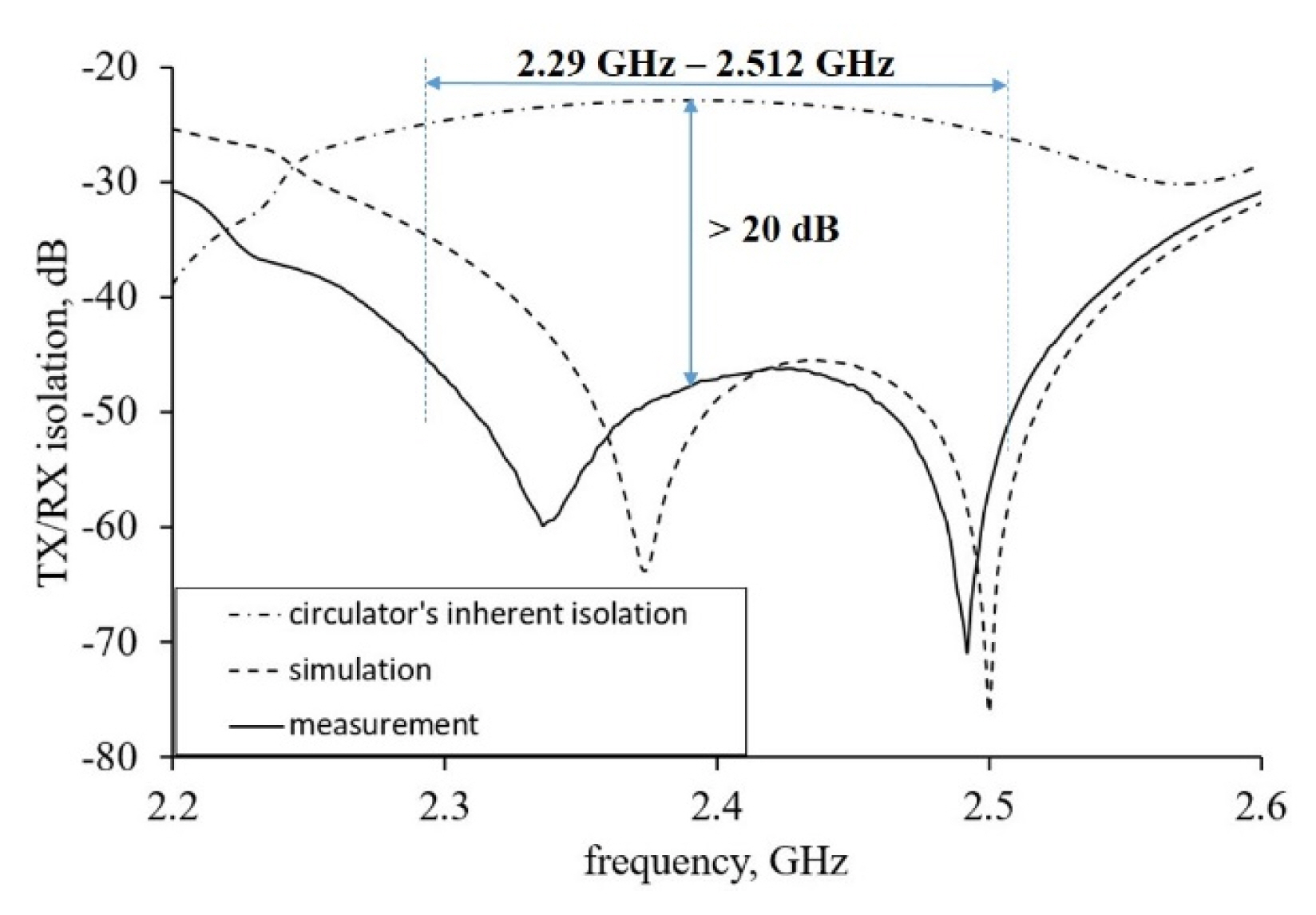
Table 1 presents a comparative analysis of the performance of the proposed LPCM and that of the existing LPCMs, showing that the proposed LPCM exhibited the widest bandwidth. The proposed LPCM and the LPCMs in [5–7] dissipated DC power because of the presence of active devices. Conversely, the LPCM in [4] did not consume any DC power because it used only passive devices, resulting in an extremely narrow bandwidth. Although the LPCM in [7] incorporated many active device chips, the authors did not report any DC power consumption. Compared with the LPCM in [5] with noise figure (NF) given, the proposed LPCM exhibited a 5-time wider bandwidth, an approximately 2.3-time reduction in DC power consumption, and identical average leakage cancellation. To enable a fair comparison between the two LPCMs, the figure-of-merit (FOM) was defined as follows:
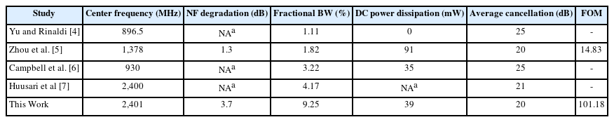
Comparison with existing LPCMs
where all the values correspond to a linear scale. The FOM of the proposed LPCM was 6.8 times higher than that of the LPCM in [5].
IV. Conclusion
In this paper, a wideband LPCM for a retrodirective RF system was proposed, fabricated, and evaluated. An NCAP was incorporated into the LPCM to enhance the isolation characteristics of the circulator, which can enhance the minimum sensitivity, linearity requirements, and filtering burden of the RF system. The proposed LPCM was demonstrated using a commercial circulator and compared with other existing LPCMs. The proposed LPCM exhibited a state-of-the-art bandwidth. To the best of our knowledge, this study is the first attempt to develop LPCM with an NCAP circuit to increase bandwidth.
Acknowledgments
This work was supported by the National Research Foundation of Korea (NRF) grant funded by the Korea government (MSIT) (No. 2022R1A2C1007712). The chip fabrication and EDA tool were supported by the IC Design Education Center (IDEC), Korea.
References
Biography

Tan-Binh Ngo received his B.S. degree in electronics telecommunications engineering from Ho Chi Minh University of Technology, Ho Chi Minh City, Vietnam, in 2016. From 2016 to 2018, he worked as an analog mix-signal circuit designer at Uniquify Inc., where he worked on SRAM and IO interface circuits for high-speed DRAM products. As of March 2018, he has been pursuing his masters–Ph.D. degree at the High-Speed Semiconductor circuit Laboratory, Department of Electronic Engineering, Kyung Hee University, Yongin, South Korea. His current research interests include high-speed memory interface designs, RF circuits for wireless power transfer systems and non-foster elements, and nonreciprocal circuits for RFIC applications.

Quang-Huy Do received his B.S. degree in mechatronics engineering from Hanoi University of Science and Technology, Hanoi, Vietnam, in 2020. He is currently pursuing his master’s degree at the High-Speed Semiconductor circuit Laboratory, Department of Electronic Engineering, Kyung Hee University, Yongin, South Korea. His current research interests include high-frequency IC design.

Sang-Woong Yoon received his B.S. degree from Yonsei University, Seoul, South Korea, in 1998, M.S. degree in electrical engineering from the Korea Advanced Institute of Science and Technology, Daejeon, South Korea, in 2001, and Ph.D. degree in electrical and computer engineering from the Georgia Institute of Technology, Atlanta, GA, USA, in 2004. From 2005 to 2006, he worked as a senior design engineer at RF Micro Devices, Billerica, MA, USA. From 2006 to 2007, he worked at Marvell Semiconductor Inc., Santa Clara, CA, USA. In 2007, he joined Kyung Hee University, Yongin, South Korea, and is a professor in Electronic Engineering now. He has authored and co-authored over 48 papers in refereed international journals and conference proceedings. His current research interests include analog/RF IC design.