Simple Dual-Feed Dual-Circular Polarization Antenna with High Isolation
Article information
Abstract
A dual-feed antenna system with circular polarization (CP) diversity and high isolation is proposed in this paper. The proposed antenna consists of two bent monopole antennas and an isosceles triangular partial GND on a single layer. To simply design an antenna with dual-feed dual-CP characteristics, CP bandwidth (BW) is optimized based on a single antenna. The proposed antenna is structurally different from conventional antennas in three ways. Structural asymmetry is realized by bending the shape of the antenna and moving the position, and thus good CP characteristics are obtained. The feeding structure is changed from a linear type to a meander type. As a result, a single monopole antenna has a CP BW of 36%. Next, an antenna system with dual-CP characteristics is introduced by implementing two monopole antennas on a single layer. In this structure, the resonant frequency is controlled by the antenna geometrical parameters, and the null frequency at S21 is controlled by the distance between the two antennas. The measured results show that the CP BW of the proposed antenna is 40.6% (1.51–2.28 GHz). The measured isolation is below −20 dB within the operating BW.
I. Introduction
Circular polarization (CP) diversity has received considerable attention in the field of communications [1]. The CP polarization diversity antenna has two advantages. First, its CP characteristics make it less susceptible to polarization mismatch than linear polarization (LP), and reduce fading loss [2, 3]. Second, isolation between two polarizations (left-hand and right-hand [LHCP and RHCP]) is very high. Therefore, different communication systems can be used at the same frequency [4].
The CP polarization diversity antenna requires a dual-feed structure to realize two CPs at the same frequency [5]. In this case, an important design consideration is the isolation characteristics. To obtain good isolation characteristics, a mutual coupling reduction structure is applied between the two resonators [6, 7]. But, it has a large size and narrow bandwidth [8, 9]. Alternatively, reconfigurable technology can be used to design a CP polarization diversity antenna with a single feed [10, 11]. However, an RF switch is applied to the radiating element, resulting in distortion of the radiation pattern. In [12], LP and CP antennas operating in the same frequency band are used on different layers, but isolation is not as high as approximately −15 dB and the polarization mismatch between LP and CP is theoretically 50%. In [13], a CP bandwidth of 7.8% is obtained using slots of different shapes, and a CP bandwidth of 2% is achieved by the use of different size H-shaped slots in [14]. In [15], a dual-feed polarization diversity antenna using a dielectric resonator (DR) structure with a CP bandwidth of 13.23%.
In this study, CP characteristics of a single-feed antenna are obtained by structural asymmetry (folded monopole and position shift). However, impedance bandwidth and axial ratio (AR) bandwidth have a narrow overlapping frequency range, so CP bandwidth is 13.2%, which is not satisfactory. Additionally, feed structure is changed to a meander shape. As a result, another resonance is added to improve the impedance bandwidth. As a result, the single monopole antenna has a broad CP bandwidth of 37.5%. When implemented as a dual-feed antenna, the CP bandwidth of the single-feed antenna is slightly changed. Further, the isolation is less than −20 dB.
II. Single Monopole Design
1. Antenna Shape
A monopole antenna with a partial ground plane is divided into a feed area with a ground plane at the bottom and a radiation area with a non-ground plane as shown in Fig. 1(a) and the simulated results are shown in Fig. 1(b) and 1(c). The antenna is implemented on an FR4 substrate with a dielectric constant of 4.4 and a thickness of 1.6 mm. In Model A, the antenna structure is symmetrical, based on the right diagonal. Therefore, AR value at the resonant frequency is 30 or higher. Model B shows a decrease in AR values at 1.2 and 2.07 GHz. However, because monopole is still symmetrical with the right diagonal line in the radiation area, it is not easy to obtain good CP characteristics.

(a) Monopole antenna with different shapes. (b) Simulated reflection coefficient and (c) axial ratio.
Fig. 2 shows current distribution formed in the two models at 2.07 GHz. In both models, surface current formed on the radiator is perpendicular to surface current formed on the ground. Two currents with a phase difference of 90° are essential for obtaining CP. However, in Model A, the current distribution on the ground is symmetrical with the right diagonal line. Therefore, the current on the ground plane is canceled. In Model B, feed structure is located on the right, so current distribution is not symmetrical. For this reason, the AR value decreases from 35 to 9 dB.

Current distribution on the monopole antenna and the ground plane: (a) Model A and (b) Model B.
2. Antenna Position
The monopole shape is bent to improve the AR characteristics, but it is still insufficient. To further improve the AR characteristics, the monopole antenna (represented by a solid line), placed in the center, is moved to the left and right, as shown in Fig. 3(a). Fig. 3(b) and 3(c) show the simulated performance of the antenna in different positions. As the monopole antenna moves 15 mm, two resonances are weakly separated, and when it reaches 30 mm, two resonances expand further, resulting in dual-resonance at 1.3 and 1.9 GHz. When the moving distance is the same, the reflection coefficient is similar regardless of the direction of movement.

(a) Monopole antenna in different positions. (b) Simulated reflection coefficient and (c) axial ratio.
The AR frequency response according to the moving distance shows three characteristics. Initially, there are two minimum points in the AR frequency response. Later, as the moving distance S increases, the structural asymmetry increases. Therefore, the AR value decreases. Finally, when the moving distance is the same, the AR frequency response shows a generally similar shape. However, the second minimum point is considerably lower when the monopole antenna moves to the left (S < 0) than when it moves to the right (S > 0).
Fig. 4(a) and 4(b) show the current distributions when S = +30 and −30 mm, respectively. The simulation is performed at a frequency corresponding to the second minimum AR. When the monopole moves to the right, the current is formed strongly near the feed structure, but the direction of the current formed on the left and right (region B) around the feed structure is reversed and canceled out. The same phenomenon occurs in region A. Accordingly, the surface current in the left diagonal direction formed on the ground plane is completely canceled out.
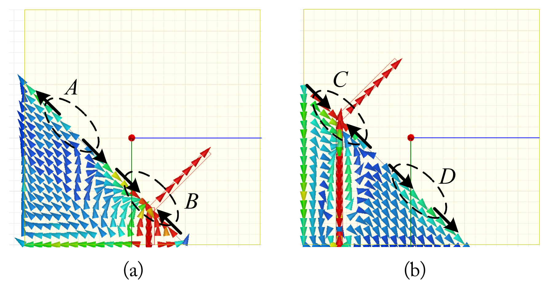
Surface current distribution: (a) S = +30 mm and (b) S = −30 mm.
In contrast, when the monopole moves to the left, the current is also formed strongly near the feed structure, but the direction of the current on the left and right is opposite depending on the C area. However, the current on the right side of the feed structure is weaker than that on the left side, and the direction of the current is formed in the same direction in region D. Therefore, the overall surface current is formed in the left diagonal (bottom right) direction. This means that CP characteristics can be well implemented.
3. Feeding Structure
To solve this problem, the meander feed structure shown in Fig. 5 is used. Fig. 6(a) and 6(b) show the simulation results for the antennas with different feed structures. At this time, the positions of the feeding points of the two antennas are set to be the same. If a meander feed is used in place of a simple feed, the resonance at 1.85 GHz is separated into two resonances, and matching is improved. The AR characteristics of the antennas with meander feed also have a wider bandwidth the antennas with simple feed. In particular, remarkably the AR frequency response above 2 GHz of the antenna with the meander feed structure is significantly better than that of the antenna with the straight feed structure.
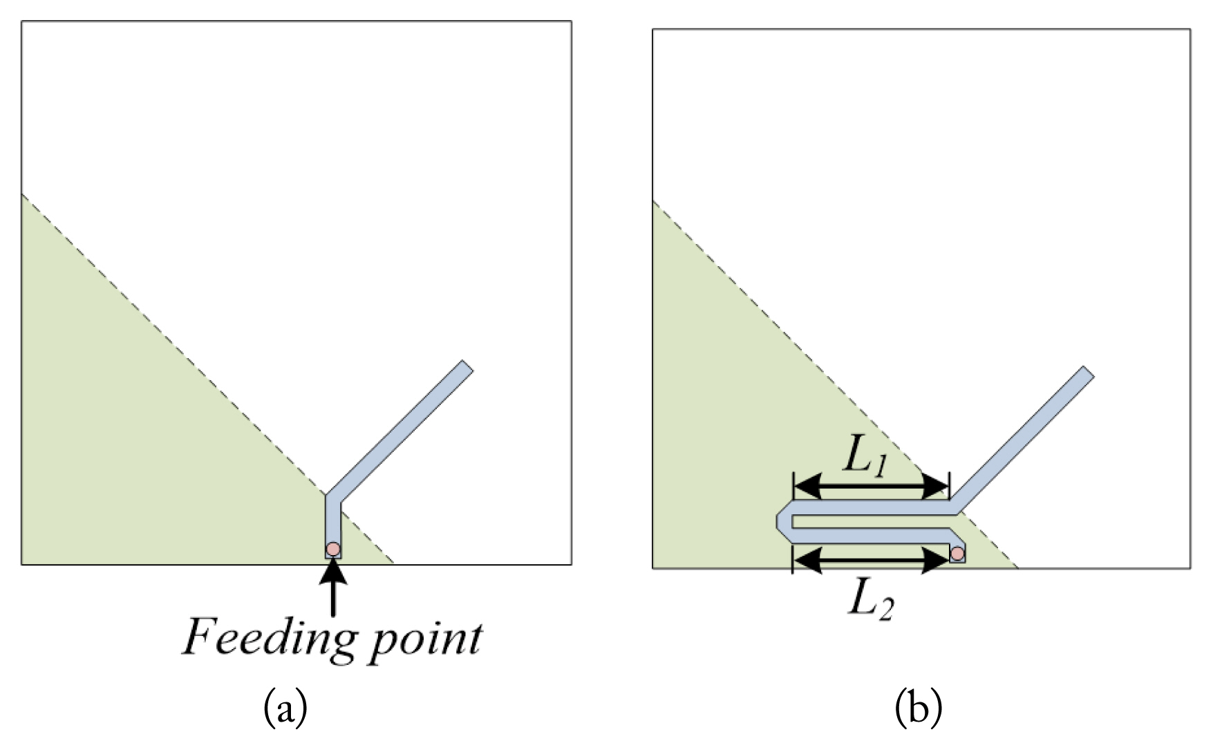
Monopole antennas with different feeding structures: (a) straight feed and (b) meander feed.

Comparison of simulation performance: (a) reflection coefficient and (b) axial ratio.
Fig. 7 shows the simulated surface current formed on the ground plane. The simulation is performed at 2.25 GHz, at which the AR values of the two structures differ significantly. When the straight feed line is used, the direction of the surface current formed on the hypotenuse is reversed based on the feeding structure, and as a result, it is canceled. This is because the vertical feeding structure is not suitable for forming a surface current in the hypotenuse direction.
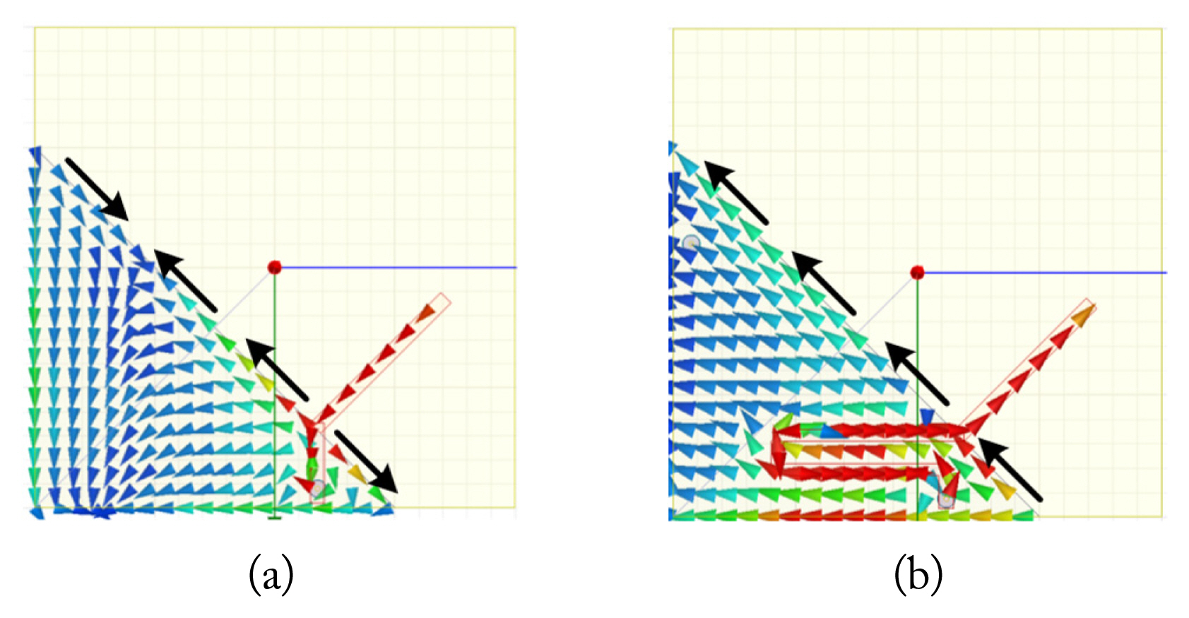
Surface current distribution at 2.25 GHz: (a) straight feed structure and (b) meander feed structure.
On the other hand, when the meander feed line is used, the direction of the surface current formed at the hypotenuse of ground (GND) is perpendicular to the monopole antenna as shown in Fig. 7(b). Since the meander line feeding structure is composed of vertical and horizontal directions, the surface current in the diagonal direction is easily formed by the sum of the two vectors. The surface current formed in the GND is perpendicular to the direction of the current formed in the monopole antenna, and the final structure acquires CP characteristics.
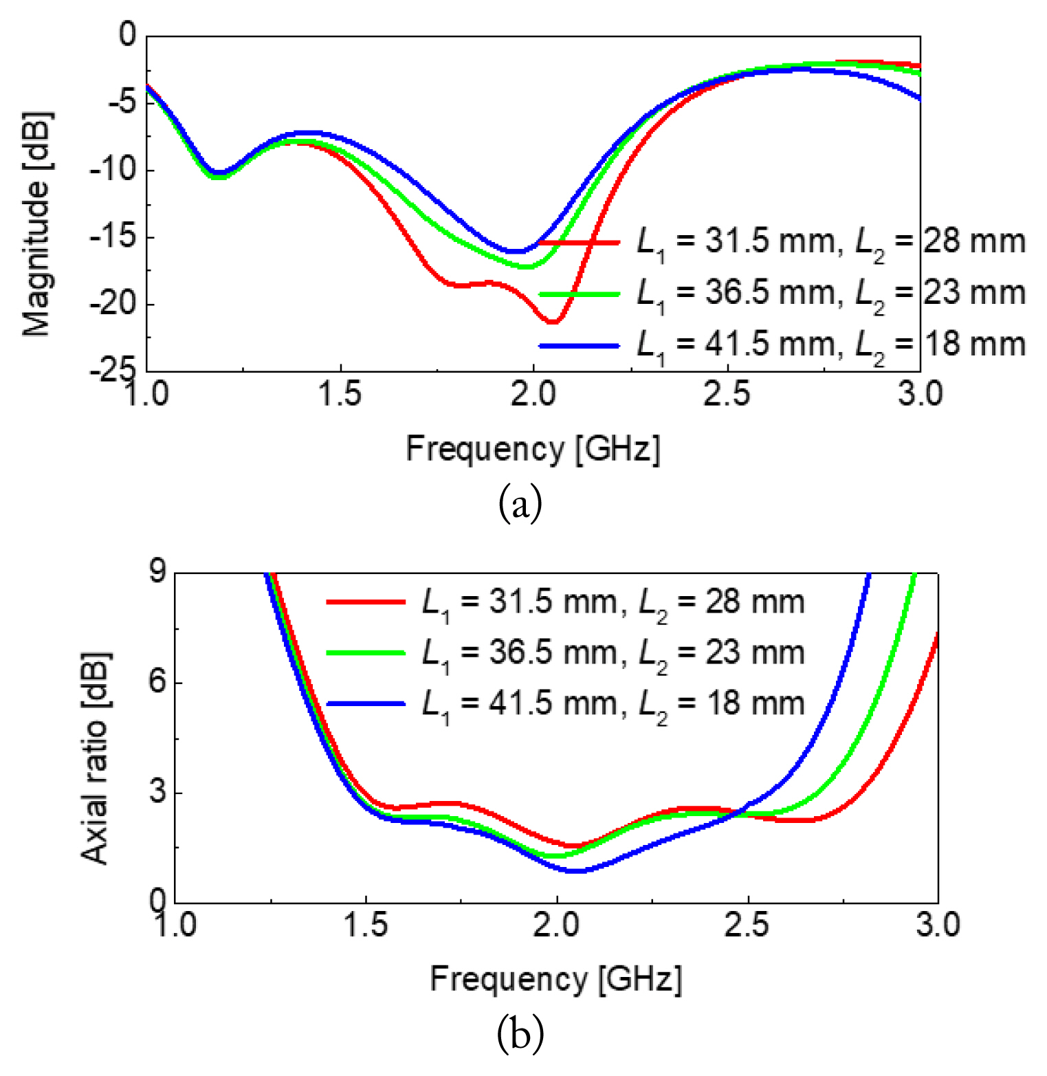
Fig. 8 shows straight feed line structures with different feeding points. Here, Fig. 8(a) is the same as Fig. 5(a). The feeding point is moved to the left by 10 mm. Accordingly, the length of the horizontal component of the feed structure increases. The simulation results are presented in Fig. 9. In the case of the straight feed line, the reflection coefficient hardly changes as the feeding point changes. In addition, the AR frequency response shows little change in the frequency band below the 2 GHz band as the position of the feeding point is changed. On the other hand, in the frequency band above the 2 GHz band, the AR frequency response characteristic improves as the feeding point moves to the left. This is because, as the feeding point moves to the left, the length of the horizontal portion of the feeding structure increases, thereby forming a horizontal component of the surface current. This is illustrated in Fig. 7(b). As can be seen from the simulation results, the straight feed line can improve the AR characteristics at the high frequency band, but there is a limit to increasing the operating bandwidth of the antenna as the reflection coefficient is maintained.
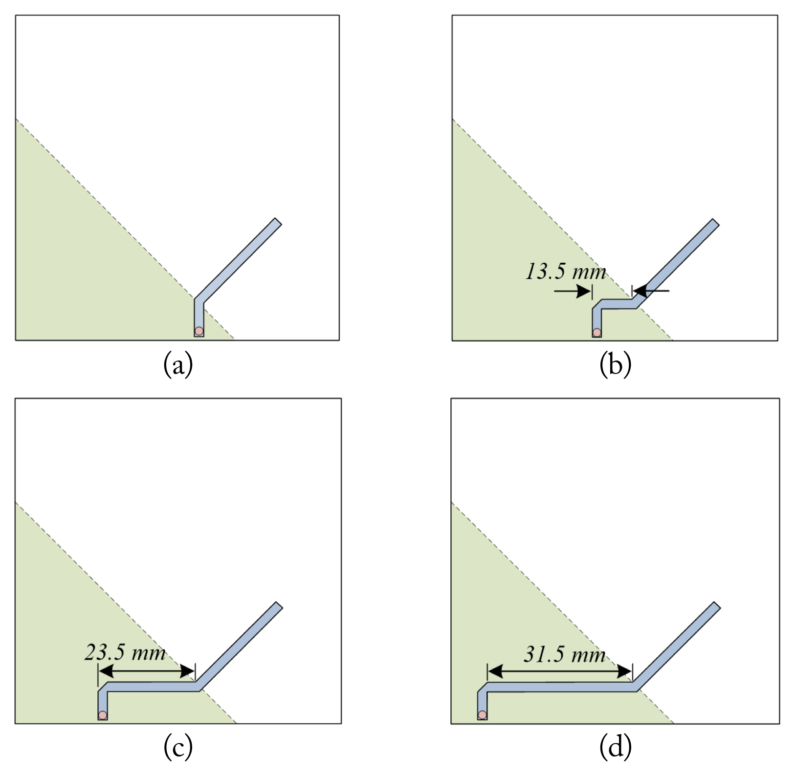
Straight feeding structure with different feeding points: (a) left shift = 0 mm, (b) left shift = 10 mm, (c) left shift = 20 mm, and (d) left shift = 30 mm.
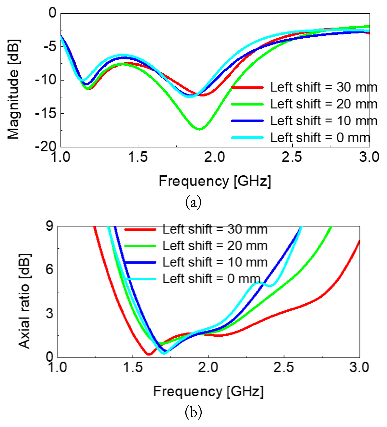
Simulated results: (a) reflection coefficient and (b) axial ratio.
Fig. 10 shows the feeding structure with different L2 in the structure of Fig. 5(b). At this time, L2 fixed at 31.5 mm. Accordingly, the feeding point moves to the left by 10 mm, respectively. Here, Fig. 10(a) means Fig. 5(b). In Fig. 10(a), where the feeding point is at the far left, there is one resonance in the 2 GHz band.
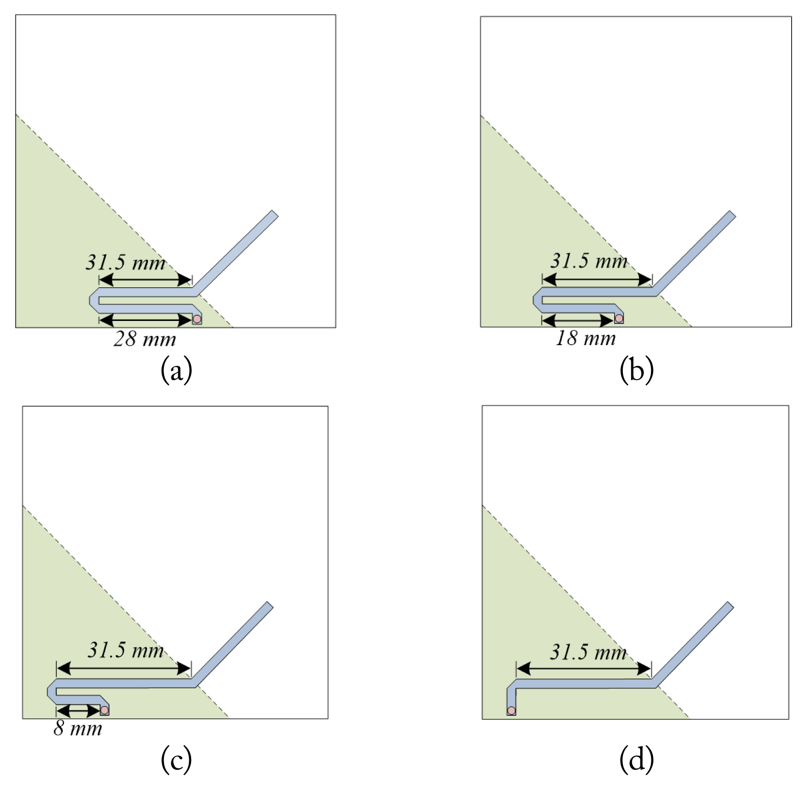
Meander feeding structure with different feeding points: (a) left shift = 0 mm, (b) left shift = 10 mm, (c) left shift = 20 mm, and (d) left shift = 30 mm.
The simulation results are presented in Fig. 11. As the feeding point moves to the right, matching is improved, and in Fig. 10(c), in which the feeding point is moved by 20 mm, the resonance in the 2 GHz band is separated. In addition, as the feeding point moves to the right, the first minimum AR point deteriorates, the third minimum AR point improves. While, the second minimum AR point hardly changes.
Simulated results: (a) reflection coefficient and (b) axial ratio.
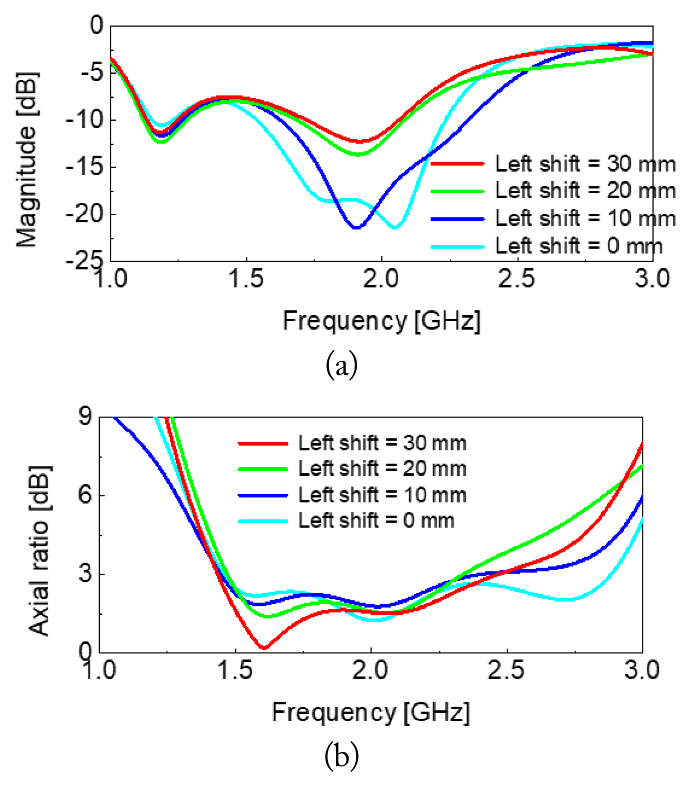
Fig. 12 compares the simulation results for the antennas using meander feeds with different L1 and L2. In all three models, the distance from the feeding point to the antenna is set to be the same. There is no change in the first resonant frequency. As the feeding point approaches corner 3, the second resonance around 1.85 GHz band is strongly split into two resonances. The AR frequency response little change when the feed structure of the antenna is changed.
Feeding structures with same total length: (a) simulated reflection coefficient and (b) simulated axial ratio.
To analyze the operating principle of the proposed antenna at three resonant frequencies, the simulated E-field distribution formed on the monopole antenna and the GND surface is investigated, and it is shown in Fig. 13. From the simulation results, it can be seen that all three resonant frequencies are formed by the monopole antenna and GND. From the viewpoint of GND, a strong E-field is formed at corner 1 at f1. f2 and f3 are split from one resonance as shown in Fig. 6, and accordingly, the two E-field distributions are very similar, and a strong E-field is formed at corners 2 and 3.

Simulated E-field distribution: (a) f1, (b) f2, and (c) f3.
4. Ground Plane Shape
To examine the antenna performance according to the shape of the GND, three different models are designed and simulated by cutting the three corners of the triangular GND. The cut length of corner 1 is set as p1. It is inserted in Fig. 14(a). As p1 increases, f1 decreases. At this time, f2 and f3 are hardly affected. As shown in Fig. 14(b), as p1 increases, the first and second minimum AR points merge into one. Also, as p1 increases, the frequency of the third minimum AR point increases. At this time, the AR characteristic gradually deteriorates.
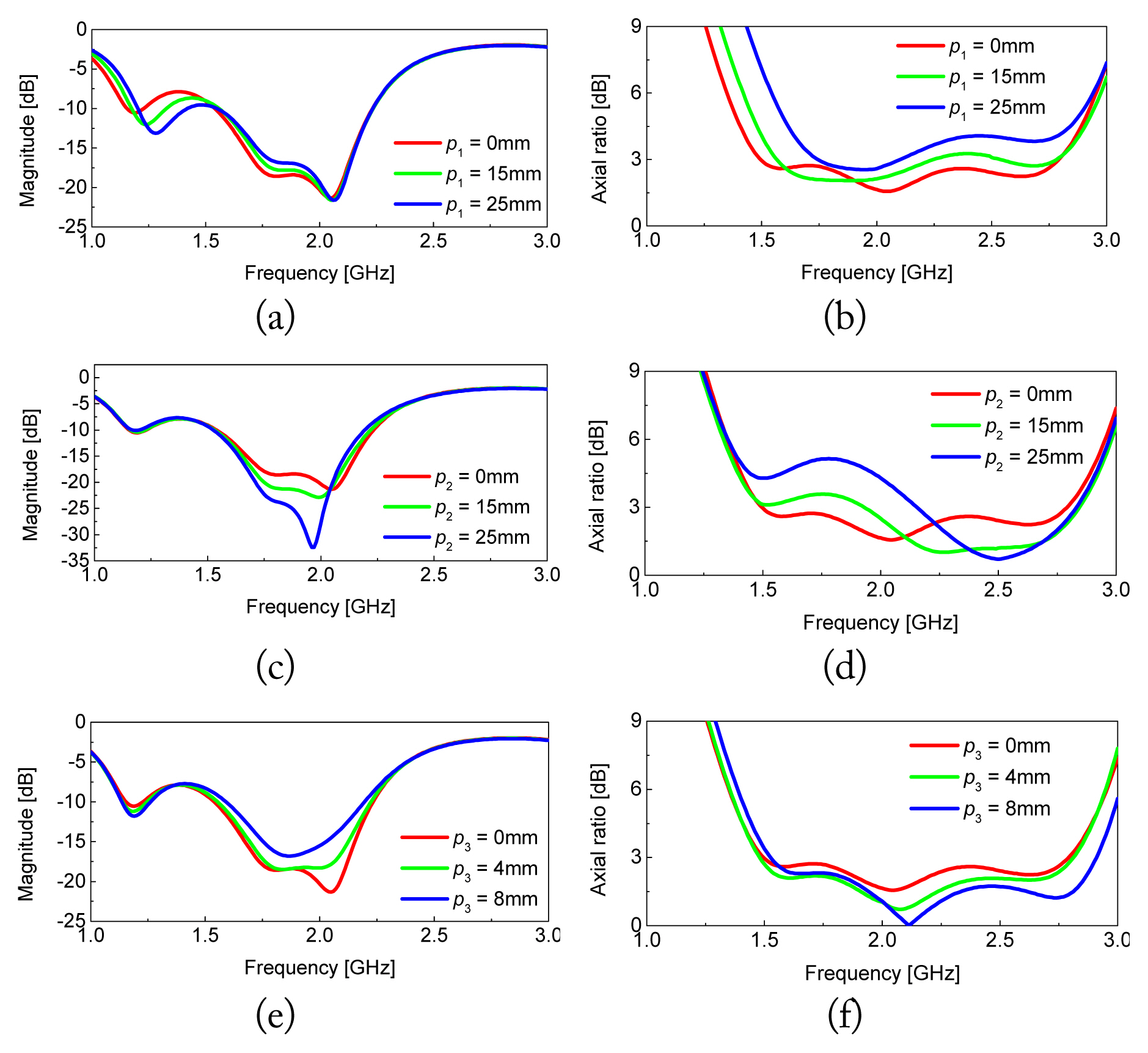
Simulated results: (a) reflection coefficient with different lengths p1, (b) axial ratio (AR) with different lengths p1, (c) reflection coefficient with different lengths p2, (d) AR with different lengths p2, (e) reflection coefficient with different lengths p3, and (f) AR with different lengths p3.
The cut length of corner 2 is set to p2. It is inserted in Fig. 14(c). As p2 increases, f2 and f3 are affected. Referring to Fig. 13(b), this is because a strong E-field is formed in corner 2 at f2 and f3. As shown in Fig. 14(d), as p2 increases, the second and third minimum AR points merge into one. The cut length of corner 3 is set as p3. It is inserted in Fig. 14(e). Depending on p3, f2 and f3 are combined or split. According to the change of p3, as shown in Fig. 14(f), there is little change in the AR frequency response.
Fig. 15 shows the proposed antenna with dual-feed dual-CP characteristics. The monopole antenna described in Section II (Fig. 5(b)) is used. Both antennas are symmetrical with respect to the right diagonal. The AR characteristic of a monopole antenna with S < 0 is considerably better than that of the monopole antenna with S > 0. However, to implement two antennas on the same plane simultaneously, an antenna with S < 0 is used.

Proposed dual-feed dual-CP monopole antenna.
When port 1 is excited and port 2 is terminated with 50 Ω, this antenna radiates LHCP wave at the +z-direction. When exchanging the excited and matched ports, the radiation is reversed. In Fig. 16, the antenna characteristics from Fig. 5(b) and Fig. 15 are compared. As seen from the simulation results, there is no significant difference in S11. Further, S21 has a characteristic of less than −18.8 dB in the operating band. Moreover, the AR frequency response shifts downward in the case of a dual-port antenna. At this time, the distance d between the two antennas is 61.2 mm.
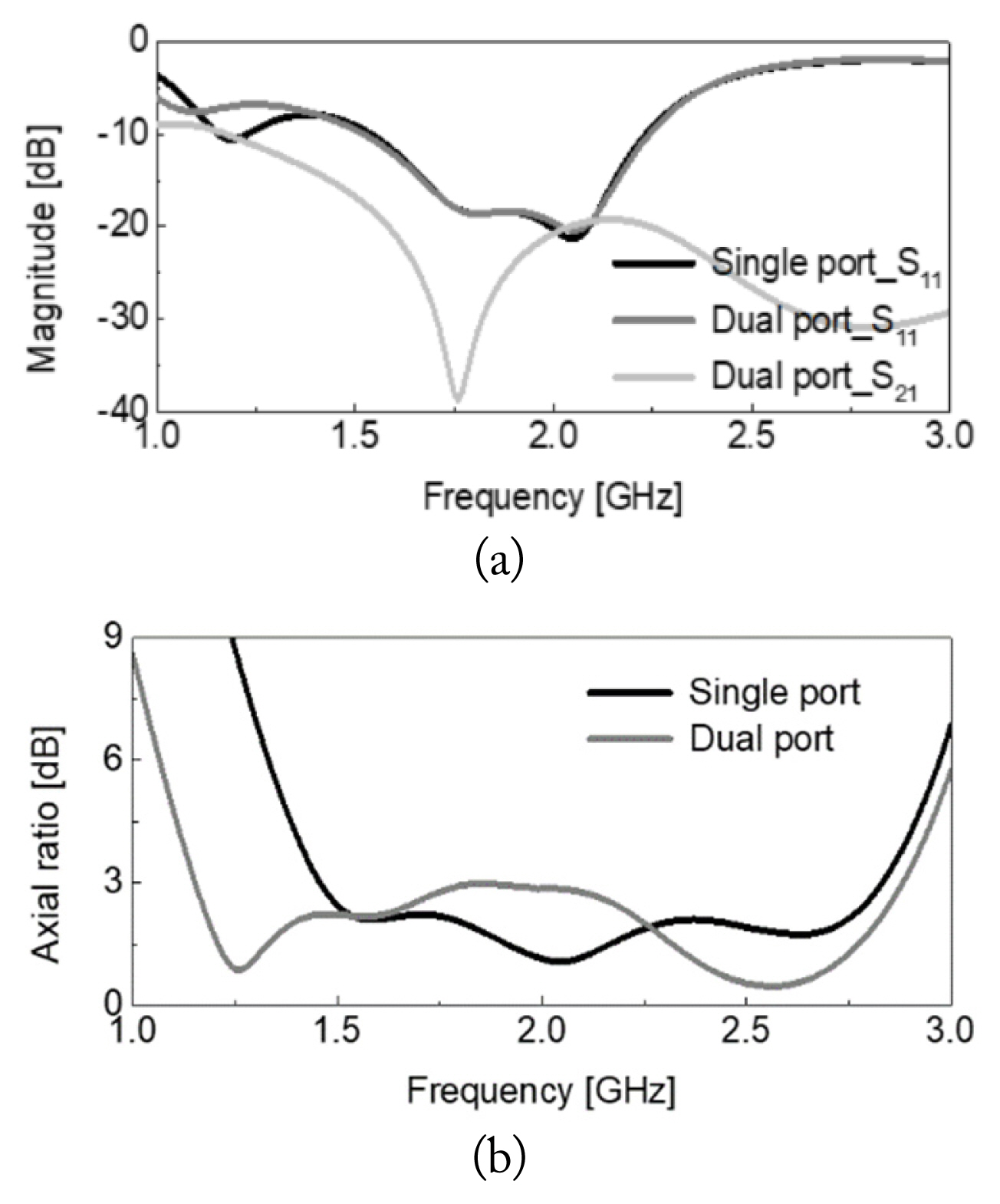
Comparison of characteristics of monopole antenna with single- and dual-port: (a) reflection coefficient and (b) axial ratio.
III. Single-Layer Dual-Feed Dual-CP Antenna
Fig. 17 shows the simulated antenna performance according to the change of the distance d. Except d, all other parameters are kept the same. As d increases, the antenna matching characteristic deteriorates somewhat, and the isolation characteristic improves by that much. This is a general phenomenon that occurs in the dual-feed dual antenna structure. As d increases, the overall AR value decreases, and the AR frequency response is improved. According to the change of d, the effect of matching and isolation is insignificant, while the degree of improvement in AR characteristics is relatively large. Based on this fact, d is finally selected as 63.2 mm.
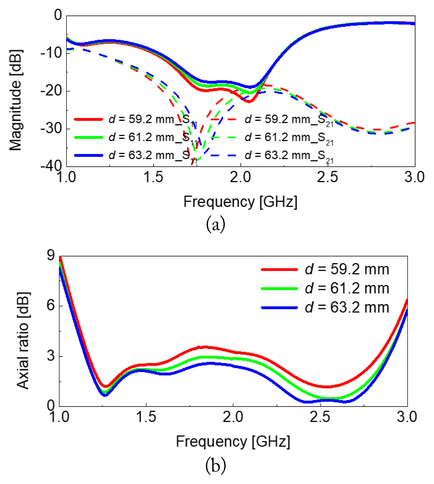
Simulated result with different distance d: (a) reflection coefficient and (b) axial ratio.
Fig. 18 shows the simulated performance of antenna with different L. As expected, as L increases, the three resonant frequencies decrease. In this case, the matching characteristics at the three resonant frequencies improves. However, since the change of f3 is faster than the change of f2, the operating bandwidth is reduced. At this time, there is almost no change in isolation characteristics. The monopole length L has little effect on the AR frequency response. As mentioned before, since the CP characteristic is determined by the position of the antenna or the GND shape, it is natural that the length of the antenna does not affect the CP characteristic.

Simulated result with different length L: (a) reflection coefficient and (b) axial ratio.
Fig. 19 shows the simulated antenna performance according to various Lf. As Lf increases, as f2 and f3 decrease, the matching characteristic at f2 and f3 deteriorates rapidly. Accordingly, the impedance bandwidth of the antenna rapidly decreases. At this time, the isolation characteristics hardly changes. The AR value in the 2 GHz band is the largest in the entire AR frequency response. When Lf is 25 mm, the AR value is exactly 3 in the 2 GHz band, which does not reduce the 3 dB AR bandwidth. In addition, as Lf increases to 28 mm and 31 mm, these values are decreasing to 2.58 and 2.49. Therefore, all three cases (Lf = 25 mm, 28 mm, and 31 mm) above can maintain a wide 3 dB AR bandwidth. However, considering the antenna manufacturing error and measurement error, it is not appropriate that Lf = 25 mm. When Lf = 31 mm, the matching characteristics of S11 are poor, so the Lf is selected as 28 mm.
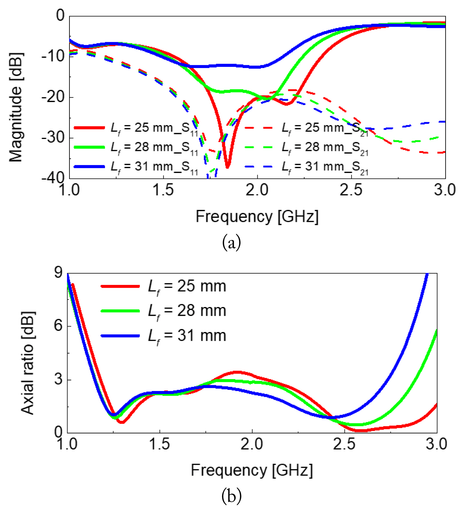
Simulated result with different length Lf: (a) reflection coefficient and (b) axial ratio.
Fig. 20 shows the simulation results of antenna with different α. As α increases, the matching characteristics deteriorate and the bandwidth hardly changes. On the other hand, the isolation characteristics are greatly affected as α changes. The isolation value becomes the highest in the 2.2 GHz band based on the operating bandwidth. As α increases, this value decreases, which is basically advantageous for obtaining good isolation characteristics. However, isolation is higher at the lower edge frequency of the bandwidth than that at 2.2 GHz. That is, it can be seen that the isolation level of the proposed antenna is determined by the isolation value at the lower edge frequency. When α = 65°, the lower edge frequency of bandwidth is 1.56 GHz, the isolation is −15 dB at this frequency. The isolation at 2.25 GHz is −30.3 dB, showing very good characteristics, but the overall isolation is actually −15 dB. As angle α starts at 25° and increases by 10°, the isolation at lower edge frequencies becomes −16.88 dB, −17.28 dB, −17.2 dB, −15.95 dB, and −15.01 dB, respectively. At this time, the isolation at the upper edge frequency becomes −17.74 dB, −18.89 dB, −20.59 mm, the matching characteristics of S11 are poor, so the Lf is selected as 28 mm.

Simulated result with different angle α: (a) reflection coefficient and (b) axial ratio.
When α decreases with respect to 45°, the AR value in the 1.87 GHz band increases. When α = 45°, AR is 2.58, and as α decreases by 10°, it increases to 3.51 and 4.34. On the other hand, when α increases, this value decreases, but the AR value in the 1.5 GHz and 2.5 GHz bands increases. Since the impedance bandwidth starts above 1.5 GHz, this does not significantly affect the overall bandwidth. In consideration of the isolation characteristics and the stable AR characteristics within the operating band, α is finally chosen as 45°.
Fig. 21 presents the simulated and measured frequency responses of the fabricated antenna. The parameters are L = 38.5 mm, W = 3 mm, Lf = 28 mm, Wf = 3 mm, d = 63.2 mm, α = 45°, and G = 75 mm. The measured overlapping CP bandwidth (S11 < −10 dB and AR < 3 dB) is 40.6% (1.51–2.28 GHz). In order to check the interference between the two antennas, the envelope correlation coefficient (ECC) obtained based on the radiation pattern is presented in Fig. 21(c). ECC in the operating band is lower than 0.01.

Simulated and measured result when port 1 is excited: (a) reflection coefficient, (b) axial ratio, and (c) ECC based on radiation pattern.
Figs. 22 and 23 present the simulated and measured radiation patterns of the proposed antenna at 1.71 and 2.03 GHz. The measured peak gain is 2.75 and 2.44 dBic. Fig. 24 shows the fabricated antenna.

Simulated and measured radiation pattern at 1.71 GHz when port 1 is excited: (a) xz plane and (b) yz plane.
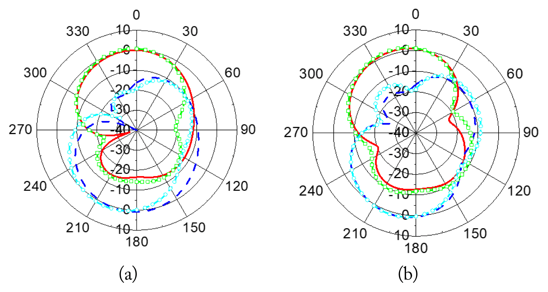
Simulated and measured radiation pattern at 2.03 GHz when port 1 is excited: (a) xz plane and (b) yz plane.

Fabricated antenna: (a) top layer and (b) bottom layer.
Table 1 compares the antenna bandwidth according to the design process. Ant-1 simply bent the monopole and improves AR frequency response characteristics, but shows the LP characteristics. To increase the asymmetry, Ant-1 shifts, it refers to as Ant-2. Ant-2 has the CP bandwidth of 15.3%. Here, the structure with meander feed instead of straight feed is Ant-3. At this time, the CP bandwidth is increased to 36.4%. The two antennas obtained from Ant-3 are symmetrically placed with respect to the right diagonal, and it refers to as Ant-4. The CP bandwidth hardly changes. Rotating the monopole in Ant-4 becomes Ant-5. CP bandwidth is increased to 40.6%.

Comparison of antenna performance according to design evolution
Table 2 summarizes the performance and size of the dual-feed dual-CP antennas. Here, λ0 is the free-space one wavelength with the lowest frequency in the operating band. Compared to the previous antennas, the size of the proposed antenna is the smallest, except in case of [16]. The CP bandwidth of the proposed antenna is narrower than that of [16–18]. A wide slot with a curved edge is used instead of a rectangular or square slot to maximize the bandwidth of the antenna in a given space [16, 17]. But, they are difficult to redesign because the numerical value or shape of the curve is not clear. However, because the authors of [18] uses a hybrid coupler, a wide CP bandwidth can be obtained, but the size is too large.
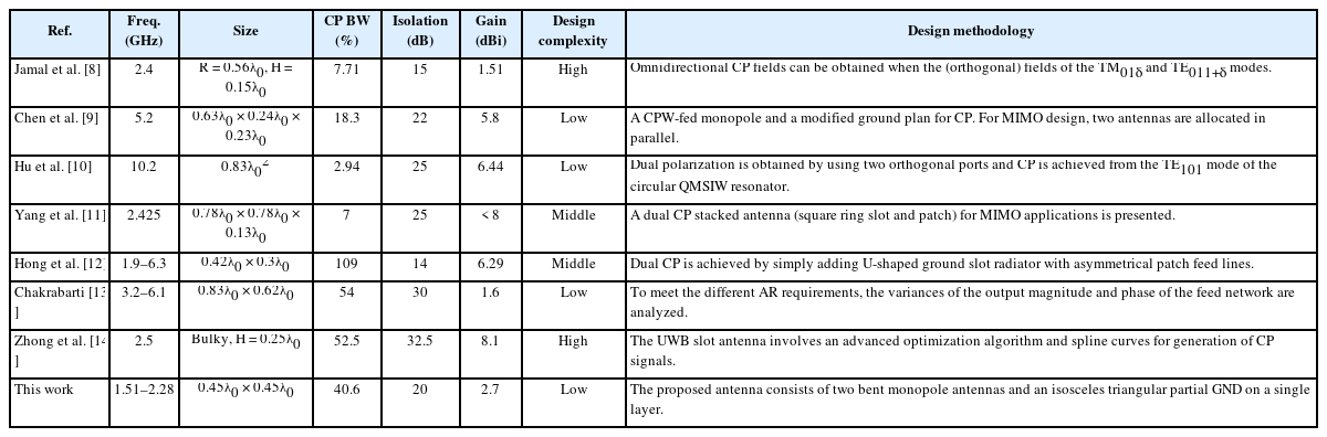
Comparison with previous dual-feed dual-CP antennas
IV. Conclusion
In this study, a dual-feed dual-CP antenna system is proposed. In the first step, based on a single monopole antenna, current distributions are formed perpendicular to each other. The antenna and feed structure are modified to optimize the AR frequency response. The location of the antenna is set considering the AR characteristics and dual-feed structure. Next, the impedance matching characteristics of the dual-feed antenna are modified by adjusting the length of the monopole and the feeding part. Further, the isolation characteristics are optimized by adjusting the distance between the antennas. The proposed antenna has a wide CP bandwidth of 40.6%, and its isolation in the operating bandwidth is less than −23 dB. The measured gain is 2.7 dBic. The antenna can be operated with either bidirectional or unidirectional characteristics, covering multiple commercial application bands including WLAN and WiMAX.
Acknowledgments
This work was supported partly by the ICT R&D program of MSIP/IITP (No. 2021-0-01024, Standard technology development and its international standardization for mission-critical smart mobility services based on 5G+) and partly by the National Research Foundation of Korea (NRF) grant funded by the Korea government (MSIT) (No. 2022R1A4A5028239).
References
Biography

Sang Won Choi received the M.S. and Ph.D. degrees in electric and electrical engineering and computer science from KAIST, Daejeon, South Korea, in 2004 and 2010, respectively. He was a senior research engineer involved in the development of multimode modem chips, from 2010 to 2014. From 2014 to 2020, he was a senior researcher with the Train Control and Communication Research Team, Korea Railroad Research Institute. Since September 2020, he is currently an assistant professor with the Department of Electronic Engineering, Kyonggi University, South Korea. His research interests include mission-critical communications, mobile communication, communication signal processing, multi-user information theory, and machine learning. He was a recipient of the Silver Prize with the Samsung HumanTech Paper Contest, in 2010.

Youngje Sung was born in Incheon, Korea, in 1975. He received the B.S., M.S., and Ph.D. degrees from Korea University, Seoul, Korea, in 2000, 2002, and 2005, respectively. From 2005 to 2008, he was a senior engineer with the Antenna R&D Laboratory, Mobile Phone Division, Samsung Electronics, Korea. In 2008, he joined the Department of Electronic Engineering, Kyonggi University, Suwon, Korea, where he is currently a professor. His research interests include reconfigurable antennas, cellphone antennas, wideband slot antennas, multifunction devices, compact circular polarized antennas, and compact dual-mode filters. Prof. Sung is serving as a reviewer for the IEEE Transactions on Microwave Theory and Techniques, IEEE Transactions on Antennas and Propagation, IEEE Microwave and Wireless Components Letters, IEEE Antennas and Wireless Propagation Letters, Progress in Electromagnetic Research, IET Electronics Letters, and IET Microwaves, Antennas and Propagation.