I. Introduction
Unlike plane waves, the phase fronts of vortex electromagnetic waves are helical, with an amplitude minimum in the boresight direction. The number of phase helix turns corresponding to the propagation distance of a wavelength is called the topological charge or orbital angular momentum (OAM) order. Theoretically, the OAM states of vortex waves are infinite and orthogonal to each other. For this reason, OAM multiplexing technology offers significant advantages in terms of increasing channel capacity and spectrum utilization [1]. In addition to wireless communication, OAM vortex waves can be applied to radar imaging [2].
In the microwave band, the ring antenna array is a simple and easy-to-implement OAM wave generation structure. For a ring array with M elements, if the feeding phase of the mth element is 2Ďl(mâ1)/M, the radiation mode after field superposition is the lth-order vortex wave [3, 4]. However, this approach requires a complex phase-shifted feed network. Although the annular traveling waves of a leaky-wave antenna based on spoof surface plasmon polaritons (SSPPs) can radiate high-order OAM waves, the size of this structure is excessively large [5]. The whispering gallery modes (WGMs) of dielectric resonators can be excited to generate helical-phase wavefronts [6, 7]. Alternatively, vortex waves can be radiated through quadrature-phase synthesis of two orthogonal degenerate TM modes of a regular patch antenna [8]. Moreover, a circular polarized patch can be used to realize the OAM mode [9]. In these cases, however, the housing of the wireless communication system cannot radiate OAM modes directly.
Various electrically small antennas, such as the planar inverted-F antenna (PIFA), have been developed for communication terminals. Further, the ground plane or metal enclosure directly functions as a radiator through coupling excitation [10]. In this case, the original self-resonant antenna serves as a non-resonant coupling element that is used to excite the characteristic modes of the ground plane [11].
The theory of characteristic modes (TCM) provides profound physical insights for antenna design, and it has been widely used in the development and construction of, for example, multi-input multi-output (MIMO) antennas [12, 13]. In the TCM, the resonance behavior of characteristic currents is related only to the structure, size, and material of the antenna itself, and it is independent of external excitations [14, 15]. Moreover, CM is a powerful tool for designing ground-mode radiation antennas [16].
There are few studies on the use of ground planes to generate OAM waves. In this paper, we perform a characteristic mode analysis (CMA) of a ground plane to determine its orthogonal degenerate modes. Then, mode synthesis is performed to radiate an OAM wave from the ground plane. Considering the practicability and simplicity of antenna structures, the rectangular ground plane is fed using a bent side strip. On the one hand, the orthogonal modes of the ground plane are excited with a phase difference of 90° to realize OAM wave radiation. On the other hand, the bent strip itself acts as a printed inverted-F antenna that can generate low-frequency radiation. Clearly, the low-frequency band can be used for normal communications, while the high-frequency band can be used for short-range high-capacity OAM communications or sensing applications.
II. Synthesis of Ground Radiation Modes
The resonant performance of the degenerate modes can be characterized in terms of mode significance MS = |1/(1 + jΝn)| [15]. Its value is in the range 0 < MS ⤠1, and Νn is the eigenvalue of the nth mode. For the state MS = 1 with Νn = 0, the characteristic mode is fully resonant. MS = 0.7 can be considered the boundary point for determining the occurrence of resonance, and in this manner, the upper and lower limit frequencies of the operating band can be determined.
The theory of mode synthesis [17] is applicable to the analysis and construction of OAM ground antennas as well. However, the ground eigenmodes are often excited through slit coupling. In this case, the characteristic currents on the conductor surface as the radiation source can be fully characterized by using the equivalent magnetic currents through the slits.
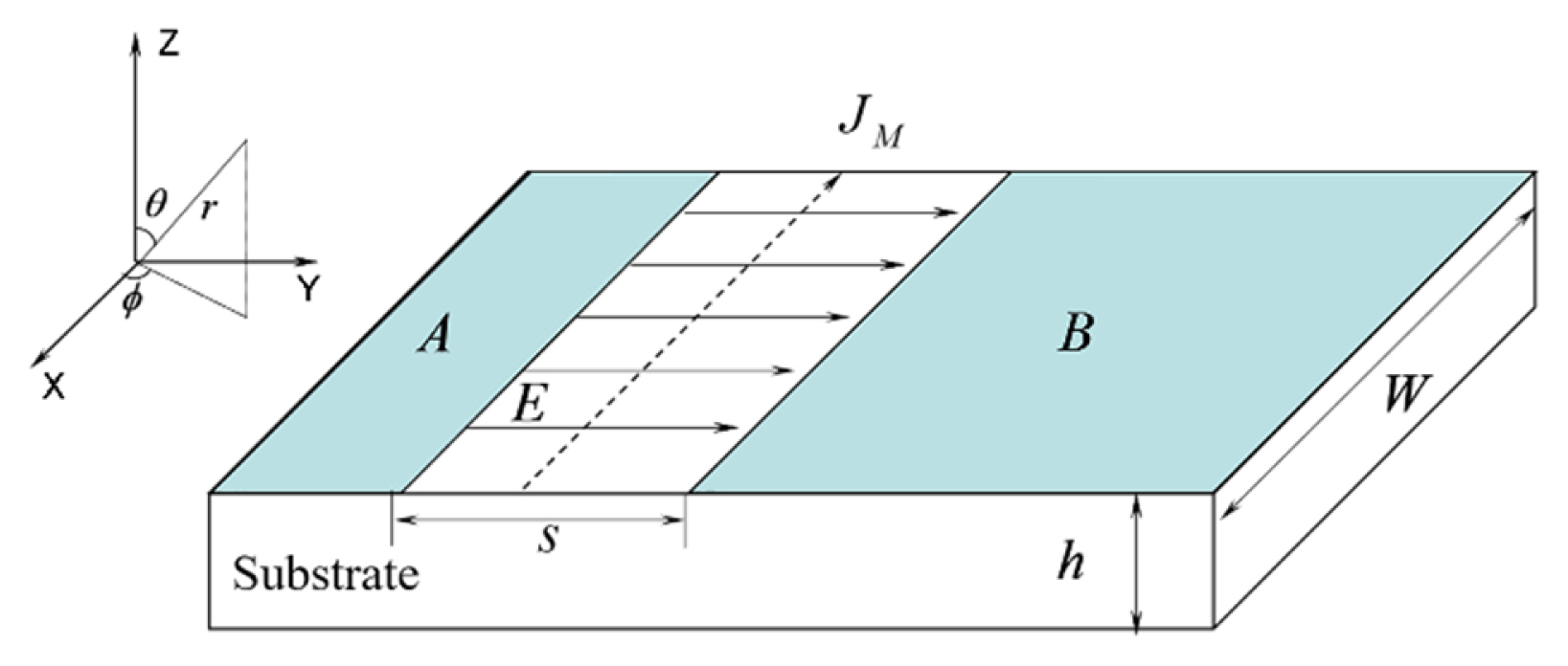
For the structure in which metal strip A and metal layer B are coplanar, as shown in Fig. 1, the TM modes on layer B can be excited through coupling of the gaps with an inter-gap spacing s. Regardless of the influence of the dielectric substrate, the radiation field generated by the TM11 mode at a distance r from the center of the rectangular patch can be expressed as follows [18]:
(1)
where β is the phase constant; W is the width of the substrate, which is equal to the length of the metal sheet; and Le is the effective length of the metal layer considering the gap effect.
Because the inter-gap spacing s is generally small and βs << 1, Eq. (1) can be rewritten as follows:
where
r e = L e 2 s i n â θ â s i n â Ď
When two orthogonally coplanar metal strips are coupled to the metal ground with a 90° phase difference, the superposition radiation field can be expressed as follows [17]:
where superscript c represents the synthetic field, and superscripts 1 and 2 indicate that the radiation fields are generated by two gap sources. Meanwhile, Îą denotes the angle between the two feed points, and Îą = Ď/2 is assumed for the case of orthogonal coupling. Because r >> re at any position in the far field, the same exp(âjβ(r â re)) can be applied. Thus, by substituting Eq. (2) into Eq. (3), we have
The synthetic field expressed as Eq. (4) has a helical phase factor eâjĎ
III. Single-Arm Antenna
1. Antenna Structure
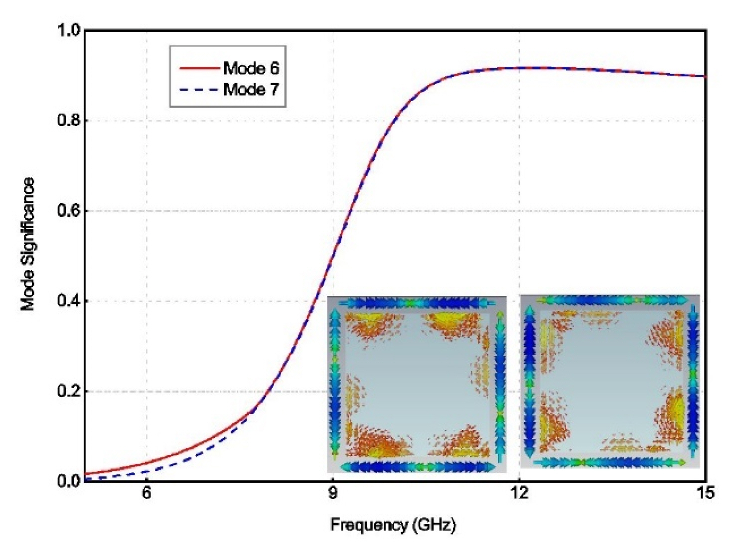
We performed a characteristic mode analysis of a 22.6-mm-long (wide) rectangular conductor on a flame retardant 4 (FR-4) dielectric substrate with a permittivity of Ér = 4.4 and thickness of h = 1.0 mm. The first 10 modes were sorted according to their eigenvalues at 9.0 GHz. A simulation was performed using CST Studio Suite, an electromagnetic simulation software program, and the resulting MS values of modes 6 and 7 and their current distributions at 10.8 GHz are presented in Fig. 2. These two modes comprise a pair of degenerate TM11 modes. Their MS values start to exceed 0.7 at 9.6 GHz and approach 1 over a wide band beyond 10.8 GHz. These findings indicate that these two modes can generate effective radiation in a broad band. To excite these two modes with the quadrature phase, the dual-fed structure with two orthogonal strips can be used. However, if a single feed method is applied, the antenna structure can be simplified greatly, and its practicality can be improved.
If the two adjacent strips on the right-angle sides are connected to form a bent strip, and a feeding port is created at the bending point, the two degenerate modes of the ground, too, can be coupled and excited. However, in this case, the two degenerate modes of the rectangular ground are excited in-phase. Therefore, we shorted one end of the bent strip to the rectangular ground to form the antenna structure depicted in Fig. 3. From the perspective of the feeding port to both sides, one side is equivalent to the transmission line of a terminal open-circuit, and the other side is equivalent to the transmission line of a terminal short-circuit. There is just a 90° phase difference between the corresponding positions on the transmission lines on both sides, such that coupled excitation of the two orthogonal modes on the ground with phase quadrature is realized. The bent strip effectively forms a PIFA with the rectangular ground.
Specifically, a square ground whose length and width are both L = 22.6 mm is considered on a substrate whose side length is W = 29.8 mm. After excluding the short-connected part of the same length as the gap, the lengths of the two side strips are L1 = 22.6 mm and L2 = 24.6 mm. Their widths are t = 1.0 mm, and the gap spacing between the strips and the ground is s = 1.6 mm. By setting the center of the rectangular conductor sheet as the origin of the coordinate system, the inner conductor of the coaxial feeder is connected to the metal strip at position a with the coordinates (x, y) = (10.9 mm, â13.4 mm), and the outer conductor is shorted to the edge of the rectangular ground at position aâ with the coordinates (x, y) = (10.9 mm, â10.9 mm).
2. Impedance Characteristics
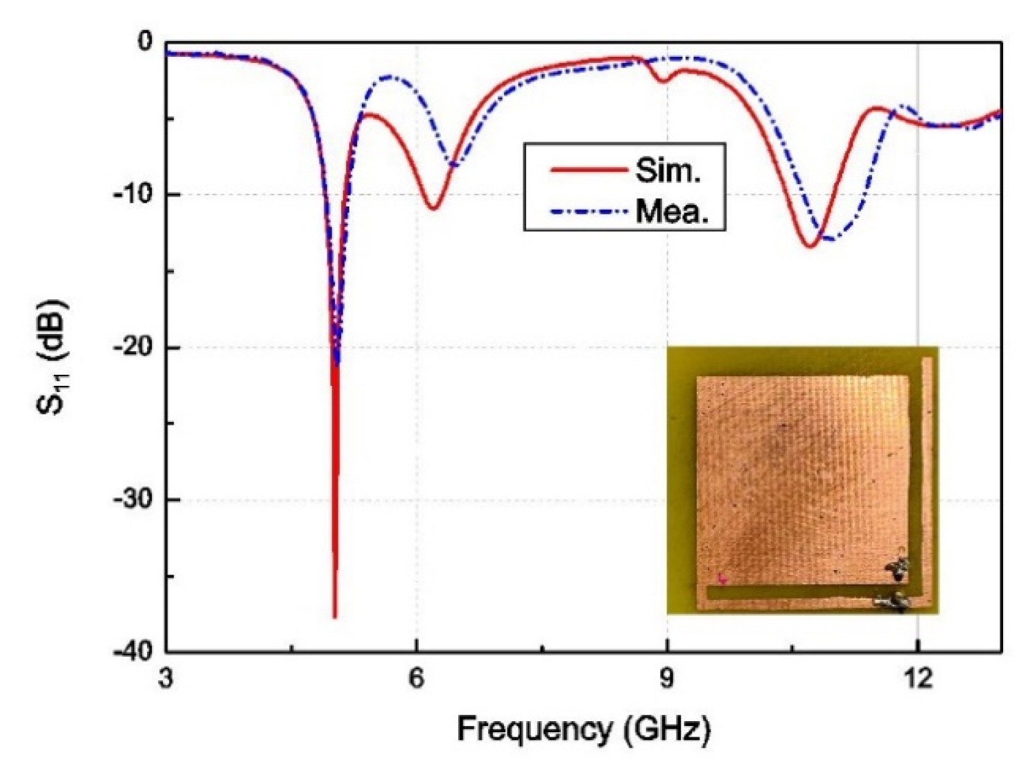
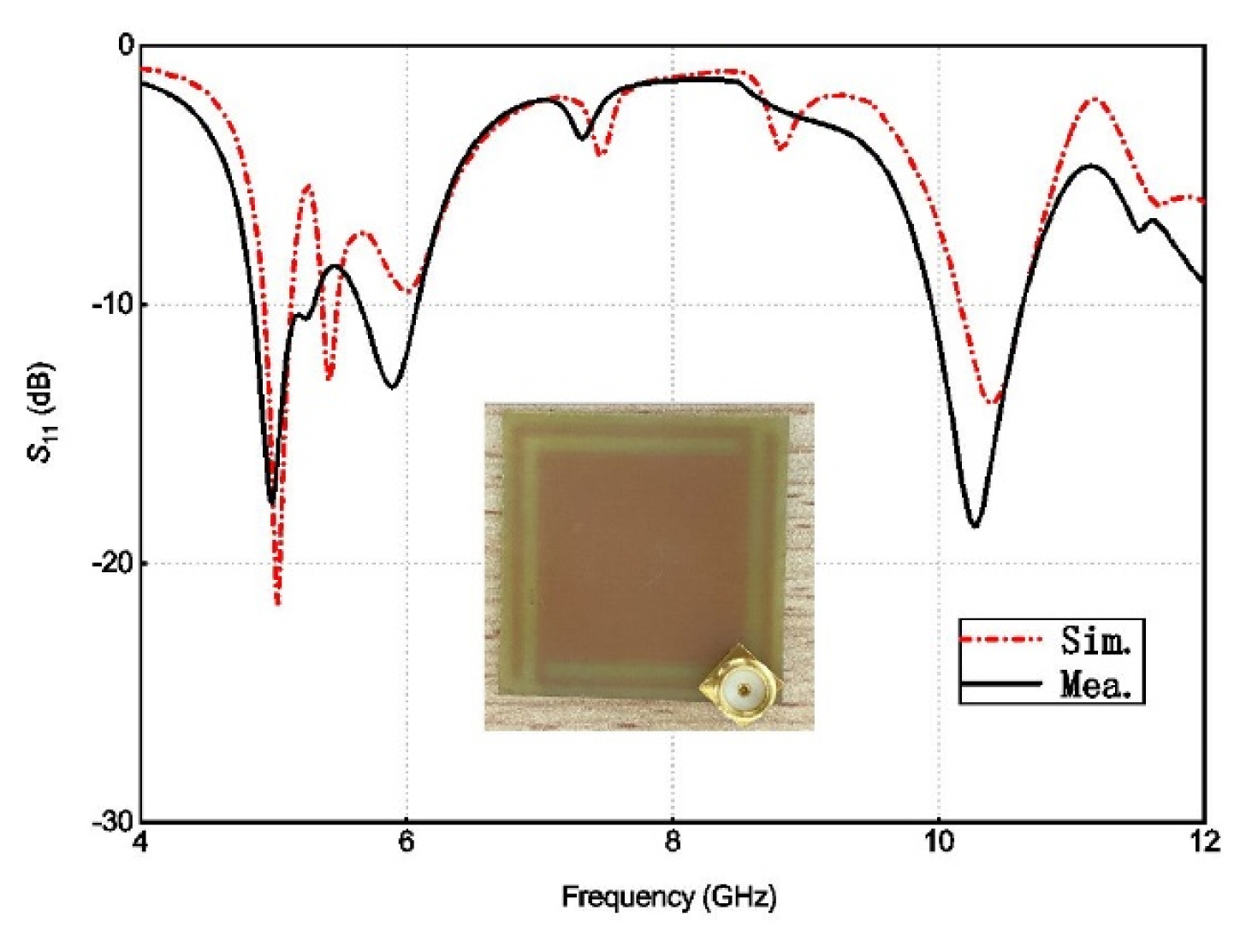
The prototype antenna, shown in the inset in Fig. 4, was fabricated by means of etching, and its impedance characteristics were tested using a vector network analyzer (AV3629D; Anritsu, Atsugi, Japan). According to the results, presented in Fig. 4, the low- and high-frequency operating bands are 4.90â5.14 GHz and 10.43â10.99 GHz, respectively. The measured low-frequency band is 4.91â5.18 GHz, and the high-frequency band is 10.62â11.37 GHz. These results are consistent with the simulation results. Meanwhile, the operating band of the fabricated antenna at the high-frequency end lies is within the range predicted based on the MS value.
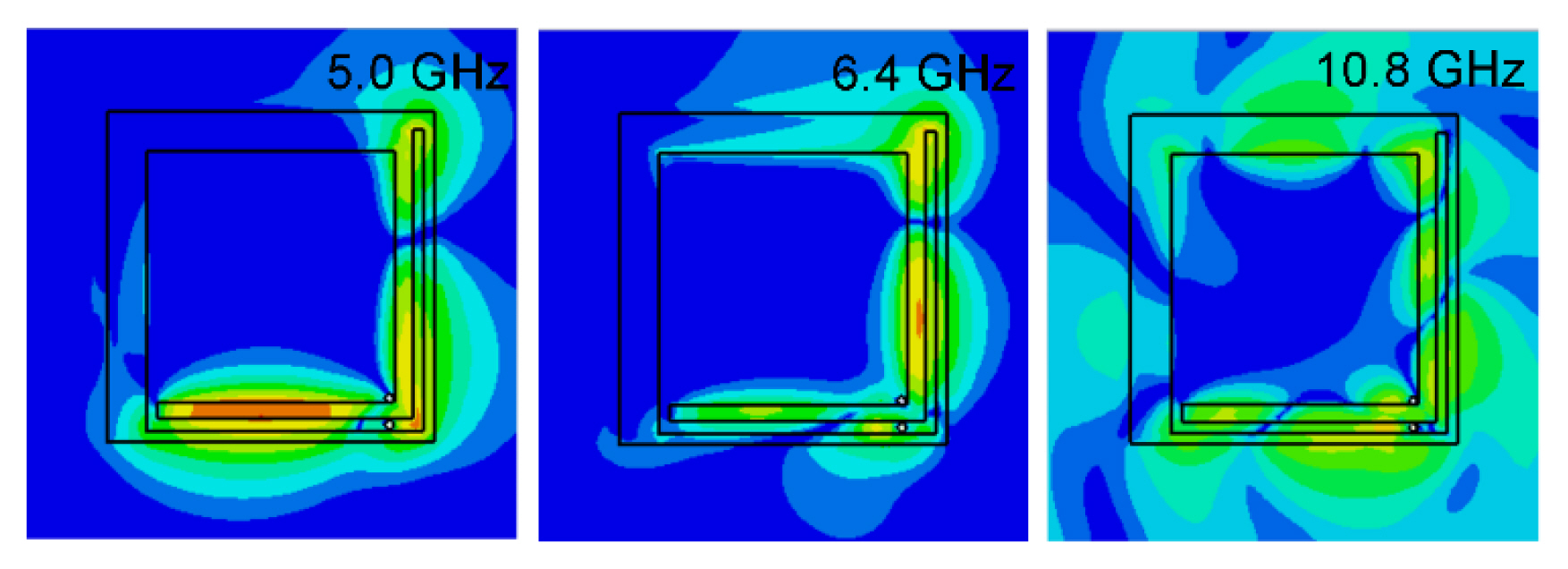
A resonance band continues to exist near 6.2 GHz. To verify the working mode of the antenna, its electric field distributions at three frequency points are depicted in Fig. 5. At 5.0 GHz, a coupled feed is generated mainly on the bottom side of the antenna, and at 6.4 GHz, this feed moves toward the right side. Accordingly, the radiation fields at the two frequencies resemble a dipole. At 10.8 GHz, a rotating field is generated, which implies that OAM waves can be formed.
3. Radiation Performance at Low Frequency
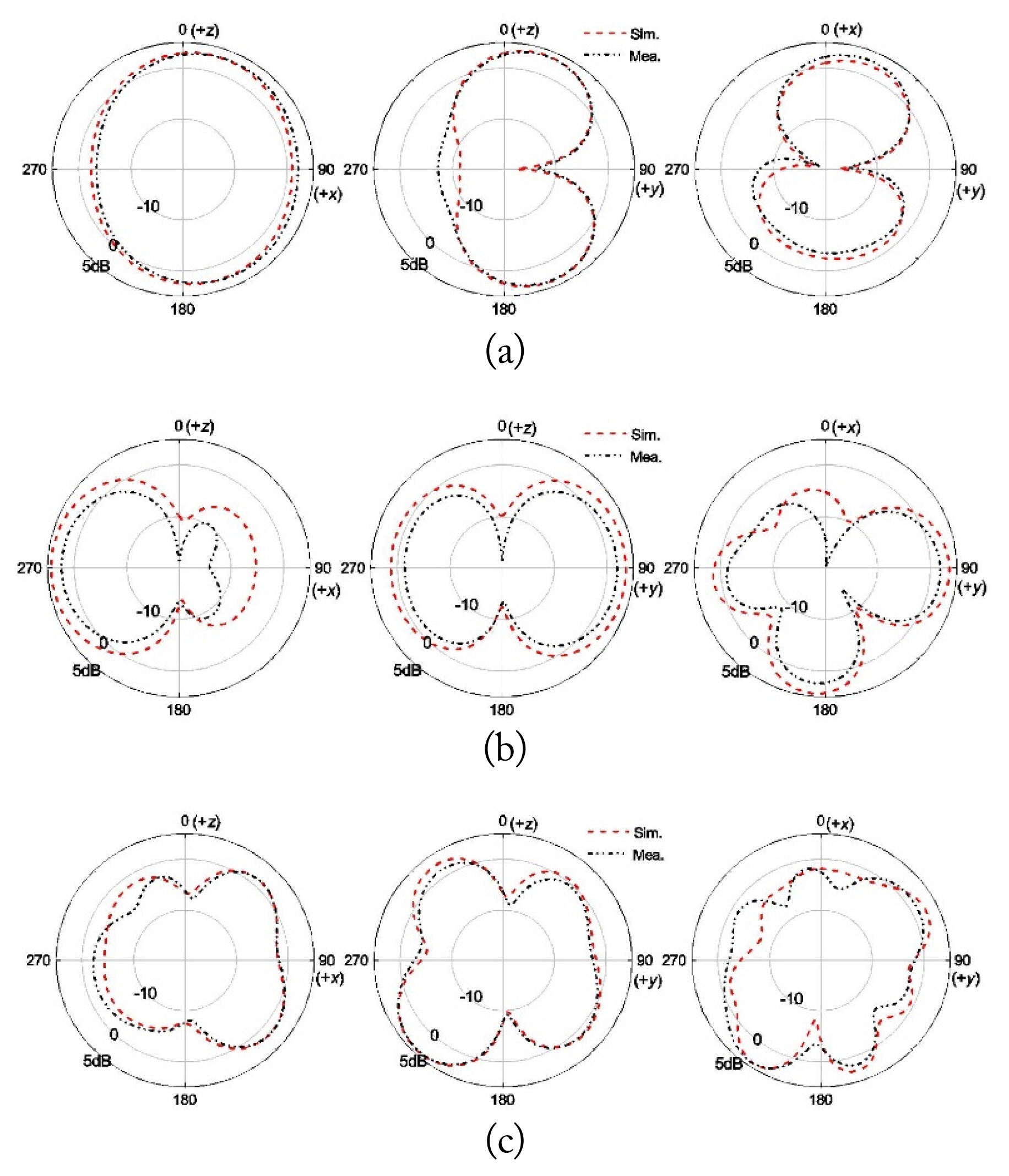
The antenna radiation patterns were tested using an NSI-300V system. The patterns obtained at 5.0 GHz are depicted in Fig. 6(a), and the maximum gain is 4.15 dB. The main radiation direction is along the xoz plane, and there is a field null on the y-axis. This antenna directionality is similar to that of a monopole placed along the y-axis. According to Fig. 5, because the rectangular ground is mainly excited by the bottom conductor strip at 5.0 GHz, surface currents flow along the y-axis The antenna patterns at 6.4 GHz are depicted in Fig. 6(b). The radiation fields are weak in the z-direction, but they are relatively strong on the xoy plane. According to the surface electric field distributions shown in Fig. 5, in this case, the field coupling is mainly determined by the vertical conductor strip. Because the vertical conductor strip is longer than the bottom strip (with the feeding point as a reference), the electric field distributed on the antenna surface represents a high-order mode. Therefore, the radiation field along the z-axis is cancelled. Meanwhile, a strong excitation field appears on the upper side, and more precisely, the current represents a high-order mode along the diagonal direction. Thus, the radiation field on the xoy plane is weak in the diagonal direction and near the +x axis.
4. OAM Performance at High Frequency
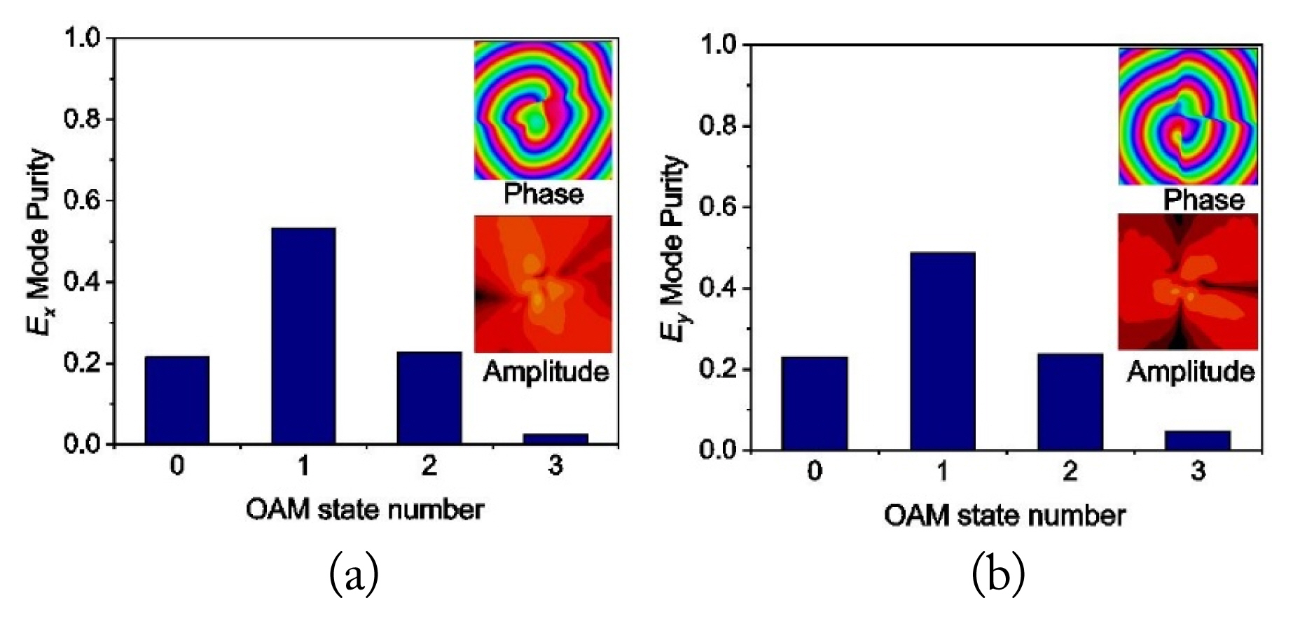
The inset of Fig. 7 shows the phase and amplitude distributions of the x- and y-components of the electric fields on a plane that is 9.6 mm away from the antenna surface at 10.8 GHz. These distributions are first-order vortex distributions. By using the loop integration method [19], OAM mode purity is realized, as depicted in Fig. 7. The first-order OAM mode purities of the x- and y-components are 53.3% and 48.7%, respectively. These results indicate that the mode purity of the antenna is not high because of the influence of the asymmetric side strips.
The antenna patterns at 10.8 GHz are depicted in Fig. 6(c). There is a depression along the z-axis direction, which is characteristic of OAM waves. For high-performance OAM waves, the patterns in the xoz and yoz planes should be left-right symmetrical to the extent possible, while the patterns in the xoy cross-section should exhibit rotational symmetry. However, the pattern symmetry in Fig. 6(c) is not high. Because of the strong field distributions on the ground plane near the coupling feed, the radiation fields are inclined toward the side strips.
IV. Performance Improvement
To improve the OAM mode purity, the antenna structure can be modified in terms of its symmetry. When four coupled strips are arranged around the rectangular ground and fed with a 90° phase difference in turn, the antenna would have high symmetry. However, this structure would be complicated for use in practice. In fact, because of the multi-port effect, the mode purity of this antenna would effectively not improve.
For this reason, we consider the highly symmetrical single-fed structure. In this case, the bent metal strip shown in Fig. 3 is symmetrically rotated by 180° along the z-axis to construct the antenna structure shown in the inset of Fig. 8. Except that the length of the metal strip on the left is 23.6 mm, which is 1.0 mm shorter than that on the right, other structural parameters have been left unchanged.
This ground-mode antenna with the single-fed structure has high symmetry. As shown in Fig. 8, the antenna has the dual-band feature. With further structural improvements, a wider band should be available at the low-frequency end. The operating band of the high-frequency end ranges from 10.22 GHz to 10.67 GHz. The test results agree well with the simulation results.
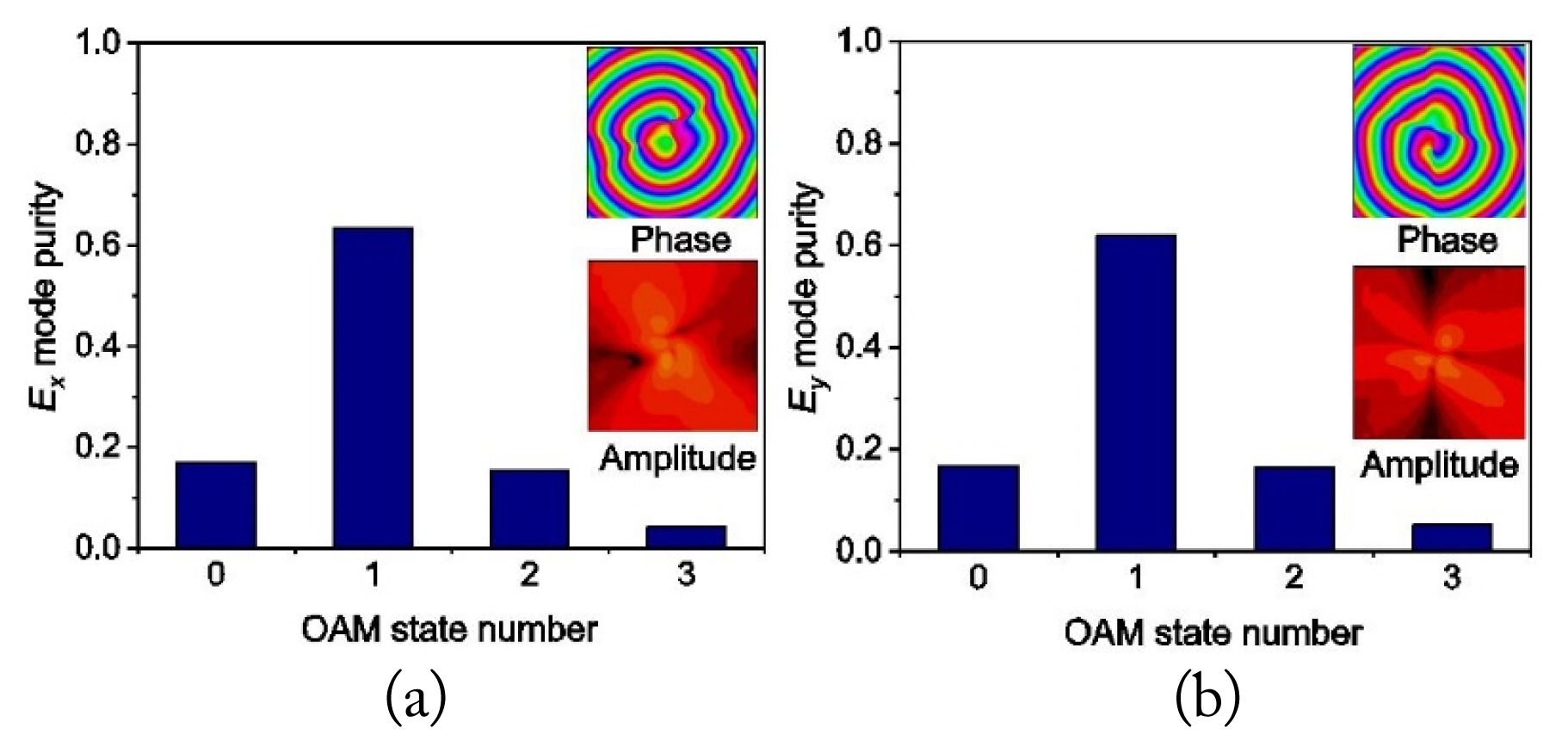
At 10.4 GHz, the phase and amplitude distributions in the plane located 9.6 mm away from the antenna surface are shown in the inset of Fig. 9. The antenna radiates first-order vortex waves, too. In this case, the OAM mode purities of the x- and y-components are 63.4% and 61.8%, respectively, which represent a large improvement compared to the results in Fig. 7.
V. Conclusion
A rectangular ground plane surrounded by two short-circuited bent conductor strips was fed from a single port to realize a dual-band antenna in several modes. At low frequencies, this structure operated as an inverted-F antenna, where the rectangular ground generated radiated fields similar to those generated by a quarter-wave monopole. Since the feed port is close to the middle of a strip, coupling between the strip and different edges of the ground plane can help realize two close resonant frequencies. At high frequencies, the bent strip excited two orthogonal TM modes on the ground plane with phase quadrature, and these modes radiated first-order OAM. The monopole-like antenna and OAM wave radiator were realized using the ground plane, and the feeding structure was simple, which means that it can be easily integrated into the terminal equipment housing.