High-Isolation 5G Repeater Antenna Using a Novel DGS and an EBG
Article information
Abstract
Repeaters have been widely used to improve communication quality and extend the coverage areas of wireless communication systems. However, mutual coupling between the Tx and Rx antennas significantly deteriorates the performance of repeater systems. This work presents a high-isolation repeater antenna operating in a frequency range of 3.6–3.7 GHz in a 5G communication system. Perpendicularly arranged microstrip patch antennas are used because this arrangement can lead to greater isolation than a parallel arrangement. However, the perpendicular arrangement results in radiation pattern distortion due to the ground mode. A novel defected ground structure (DGS) is developed to suppress the ground mode and simultaneously reduce the mutual coupling between the Tx and Rx antennas. An electromagnetic bandgap (EBG) is additionally employed to further increase isolation. The measurement results of a fabricated repeater antenna show no radiation pattern deformation and an isolation improvement of 28 dB over the repeater antenna without the DGS and EBG.
I. Introduction
Modern communication technology has entered the 5G era. The high speed of 5G wireless communication is due to large bandwidths in higher frequency bands [1–7]. However, the attenuation of 5G signals is greater than that of LTE signals, since it is proportional to the square of the frequency [8]. Repeaters are widely used to improve communication quality and extend the coverage areas of communication systems [9]. However, mutual coupling between repeaters’ Tx and Rx antennas deteriorates RF system performance [10–14]. Specifically, the excessive feedback generated by mutual coupling can result in magnitude/ phase errors and may cause a repeater to undergo fatal oscillation [15]. Therefore, high isolation between the antennas is required [16–18]. In recent years, various methods have been proposed to reduce mutual coupling, including orthogonal arrangements [19], uniplanar compact electromagnetic bandgaps (EBGs) [20], mushroom-like EBGs [21], helical-shaped EBGs [22], dumbbell defected ground structures (DGSs) [23], and slotted-complementary split-ring resonators [24].
Here, we propose a repeater antenna with high isolation for a 5G communication system operating in a range of 3.6–3.7 GHz. To improve the isolation between the Tx and Rx antennas, microstrip patch antennas are arranged perpendicularly to each other. This arrangement allows each antenna to excite orthogonal ground modes, which reduce the mutual coupling between the Tx and Rx antennas. However, the perpendicular arrangement inevitably deteriorates the radiation pattern of one antenna, as the ground mode has a strong effect on the antenna’s radiation. The antenna’s radiation pattern can be modified by altering the surface current density distribution on the ground plane [25–31].
Thus, a novel DGS is developed to alter the surface current density distribution on the ground thus alleviating the deformation of the antenna’s radiation pattern. By reducing the ground mode effects, the novel DGS can also enhance isolation between the Tx and Rx antennas. To further increase isolation, an EBG structure is also employed [32]. The use of the DGS and EBG results in an isolation improvement of up to 28 dB over a conventional repeater antenna.
The remainder of this paper is organized as follows: in Section II, we present the isolation and ground mode effects when the Tx and Rx antennas are perpendicularly arranged. Next, we describe the designs of the novel DGS and EBG and a simulation of the repeater antenna’s performance. Subsequently, we report the experimental results of a fabricated repeater antenna. Finally, we make concluding remarks.
II. Design
The Tx and Rx microstrip patch antennas have a width of 25.8 mm (0.31λ0) and a length of 17.6 mm (0.21λ0) and operate in a frequency range of 3.6–3.7 GHz, where λ0 is the free-space wavelength at the lowest frequency within the operating frequency. An FR-4 substrate is used (thickness = 2.4 mm, ɛr = 4.4, tanδ = 0.02). As shown in Fig. 1, the microstrip patch antennas are arranged perpendicularly to achieve better isolation, since the excited ground modes are perpendicular to each other.
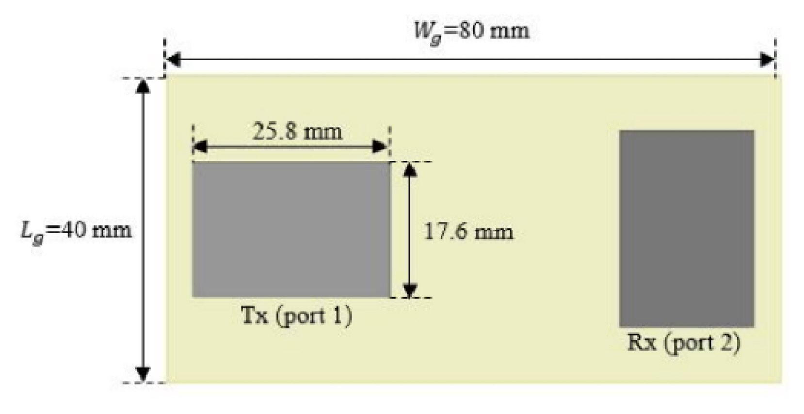
Perpendicularly arranged microstrip patch antennas.
Fig. 2 shows the simulation results of the perpendicularly arranged antennas. As shown in Fig. 2(a), the isolation is approximately 40 dB, and the return losses of the Tx and Rx antennas are greater than 10 dB in the frequency of interest. Fig. 2(b) and 2(c) displays the radiation patterns of the Tx and Rx antennas, respectively. The boresight realized gains of the Tx and Rx antennas are 5.78 and 1.75 dBi, respectively. Although the perpendicular antenna arrangement results in isolation enhancement, the radiation pattern of the Rx antenna is significantly deformed, as illustrated in Fig. 2(c). Fig. 3 shows the ground modes excited by the Tx and Rx antennas. Since the ground mode depends on the length of the ground [33], the radiation pattern of the Rx antenna is significantly affected by the ground mode excited by it, whereas the Tx antenna is barely affected, as shown in Fig. 3.

Simulation results of the designed repeater antenna: (a) S-parameters, (b) Tx antenna radiation pattern, and (c) Rx antenna radiation pattern.
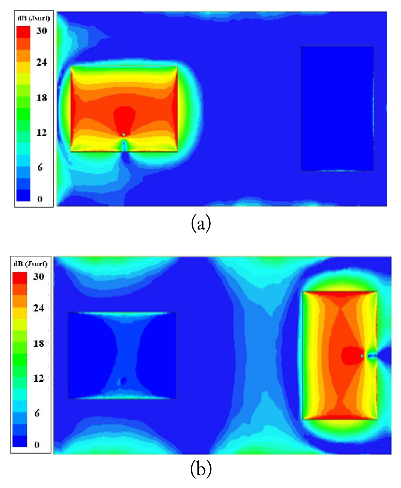
Surface current density distribution on the ground plane: excitation by (a) the Tx antenna and (b) the Rx antenna at 3.65 GHz.
Therefore, the effect of the ground mode on the Rx antenna radiation pattern should be reduced by modifying the surface current density distribution on the ground. To do so and enhance the isolation between the Tx and Rx antennas, a novel DGS is used. Fig. 4 shows a schematic of the proposed DGS, which consists of an H-shaped slot, four large fork-shaped slots, and two small fork-shaped slots. Fig. 5(a) shows the simulated S21 of the repeater antenna with the novel DGS with respect to L1. An investigation of the influence of slot length on isolation yields an optimal length of L1 = 8.29 mm. For L2, and optimal length of 20 mm is obtained, as shown in Fig. 5(b). After optimizing other geometric parameters, the final DGS is obtained. A schematic of the proposed DGS is shown in Fig. 6(a). The S-parameters of the repeater antenna with the proposed DGS are shown in Fig. 6(b). Isolation is improved by up to 23 dB compared to a conventional repeater antenna without the DGS operating in the same frequency range. An investigation of the surface current density on the ground for the repeater antenna with the proposed DGS shows a significant suppression of the surface current of the ground mode (Fig. 7(a)) compared to the antenna without the DGS (Fig. 3(b)). As shown in Fig. 7(b), the DGS confines the surface current density within it, thereby reducing the radiation pattern deformation of the Rx antenna and improving the boresight realized gain by 2.6 dB, as shown in Fig. 7(c).
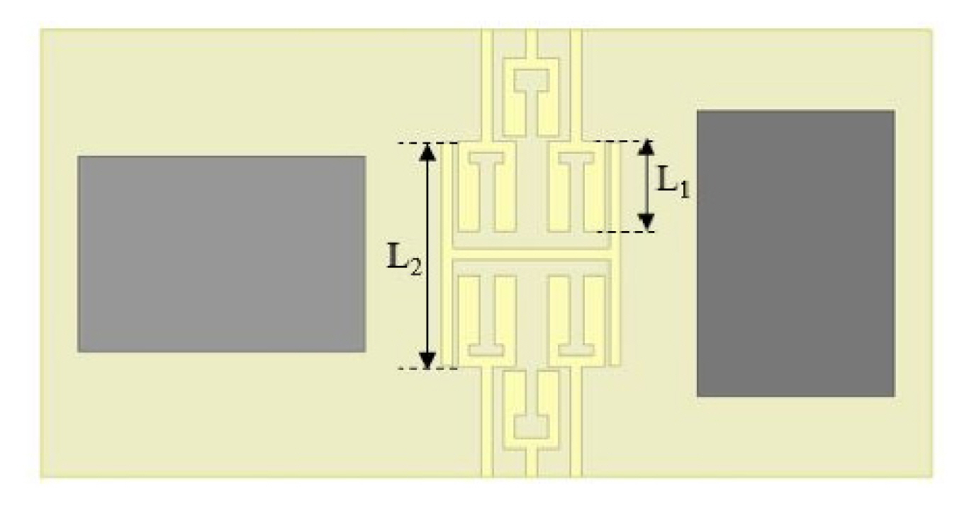
Schematic of the novel DGS.
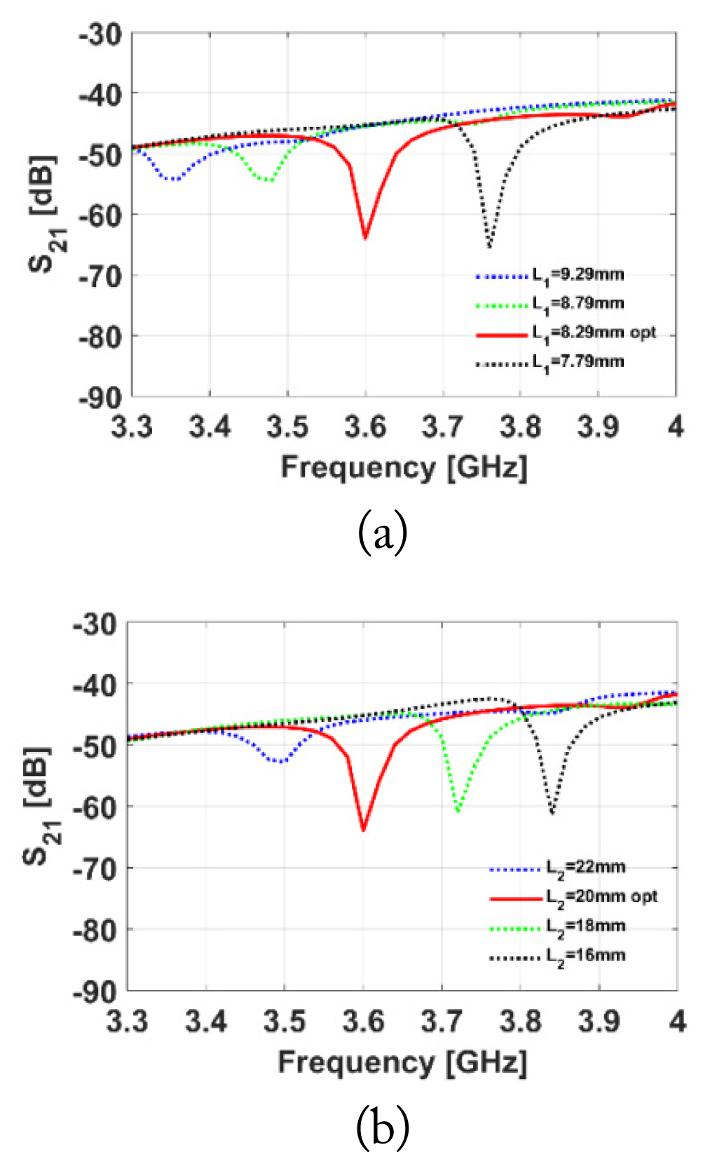
Simulated S21 versus slot lengths: (a) L1 and (b) L2.
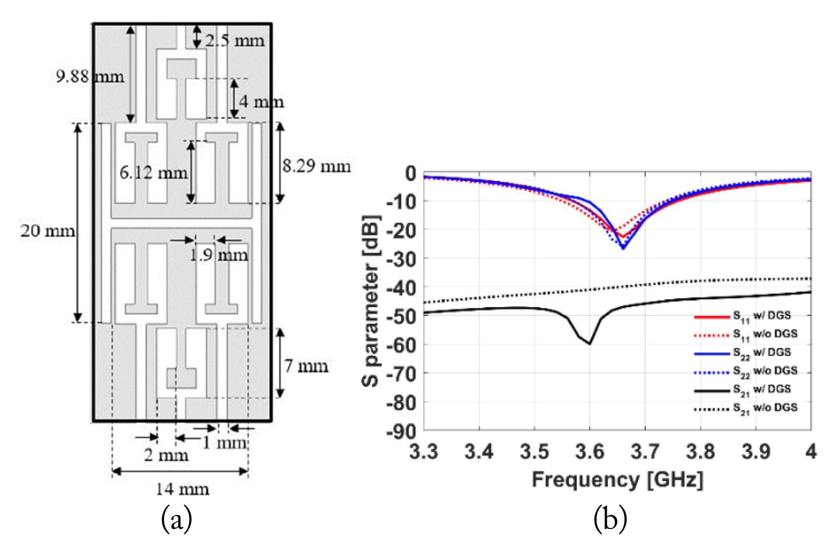
Optimization results of the proposed DGS: (a) schematic and (b) simulated S-parameters.
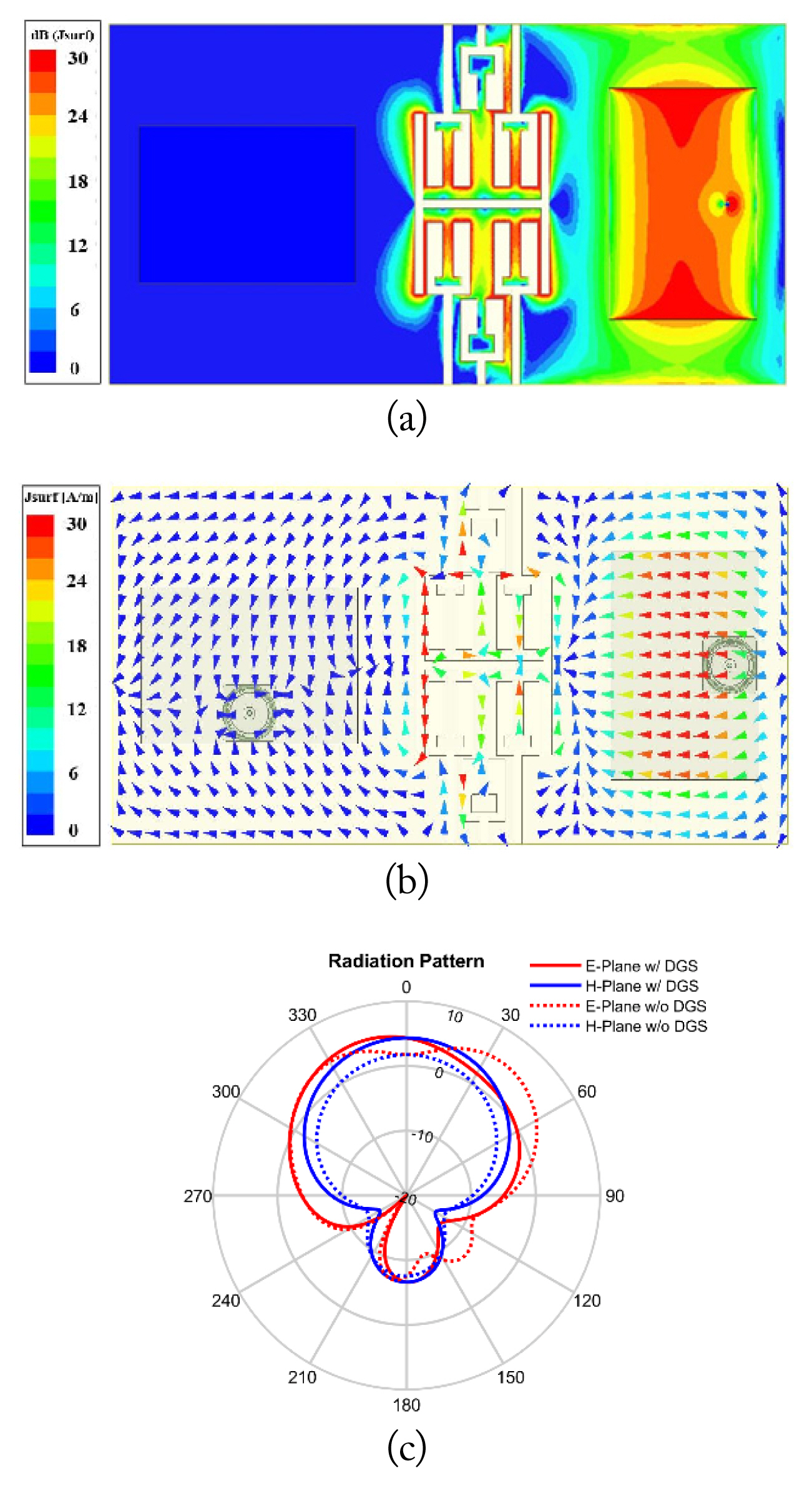
Simulation results of the repeater antenna with the novel DGS: (a) surface current density distribution at 3.65 GHz, (b) surface current density vector distribution at 3.65 GHz, and (c) Rx antenna radiation pattern.
To further enhance isolation, an EBG that has a via hole with a diameter of 0.4 mm is also used. Fig. 8(a) shows a schematic of the EBG. The band-stop frequency can easily be shifted by adjusting the length of the branch (L3) [34]. Fig. 8(b) shows the frequency shifts with respect to L3. As shown in Fig. 8(c), the EBG improves the isolation between the Tx and Rx antennas by about 15 dB.
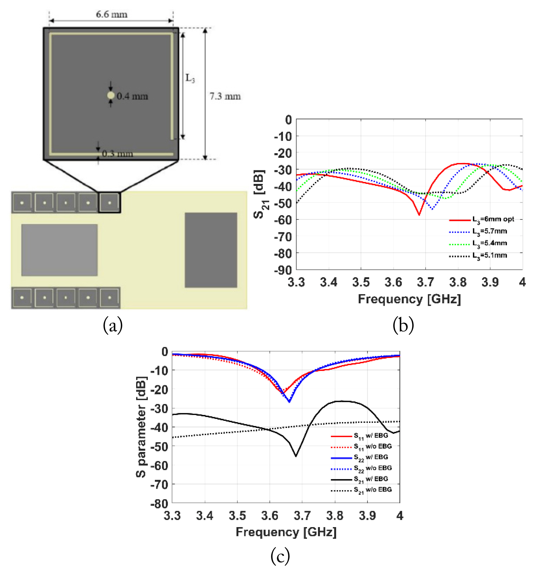
EBG: (a) schematic, (b) simulated S21 versus branch length (L3), and (c) simulated S-parameters.
Fig. 9 displays a schematic of the repeater antenna with the proposed DGS and EBG. Fig. 10 shows the simulated S-parameters and radiation patterns of the proposed repeater antenna. As shown in Fig. 10(a), the isolation bandwidth is broadened by simultaneously employing the novel DGS and EBG. Isolation is improved by up to 20 dB compared to the conventional repeater antenna. Moreover, the radiation pattern deformation of the Rx antenna is significantly reduced, as illustrated in Fig. 10(c). The boresight realized gain of the proposed Rx antenna is improved by about 2.3 dBi compared to the conventional antenna.
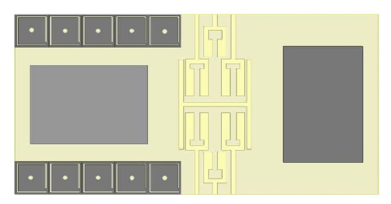
Schematic of the repeater antenna with the novel DGS and EBG.
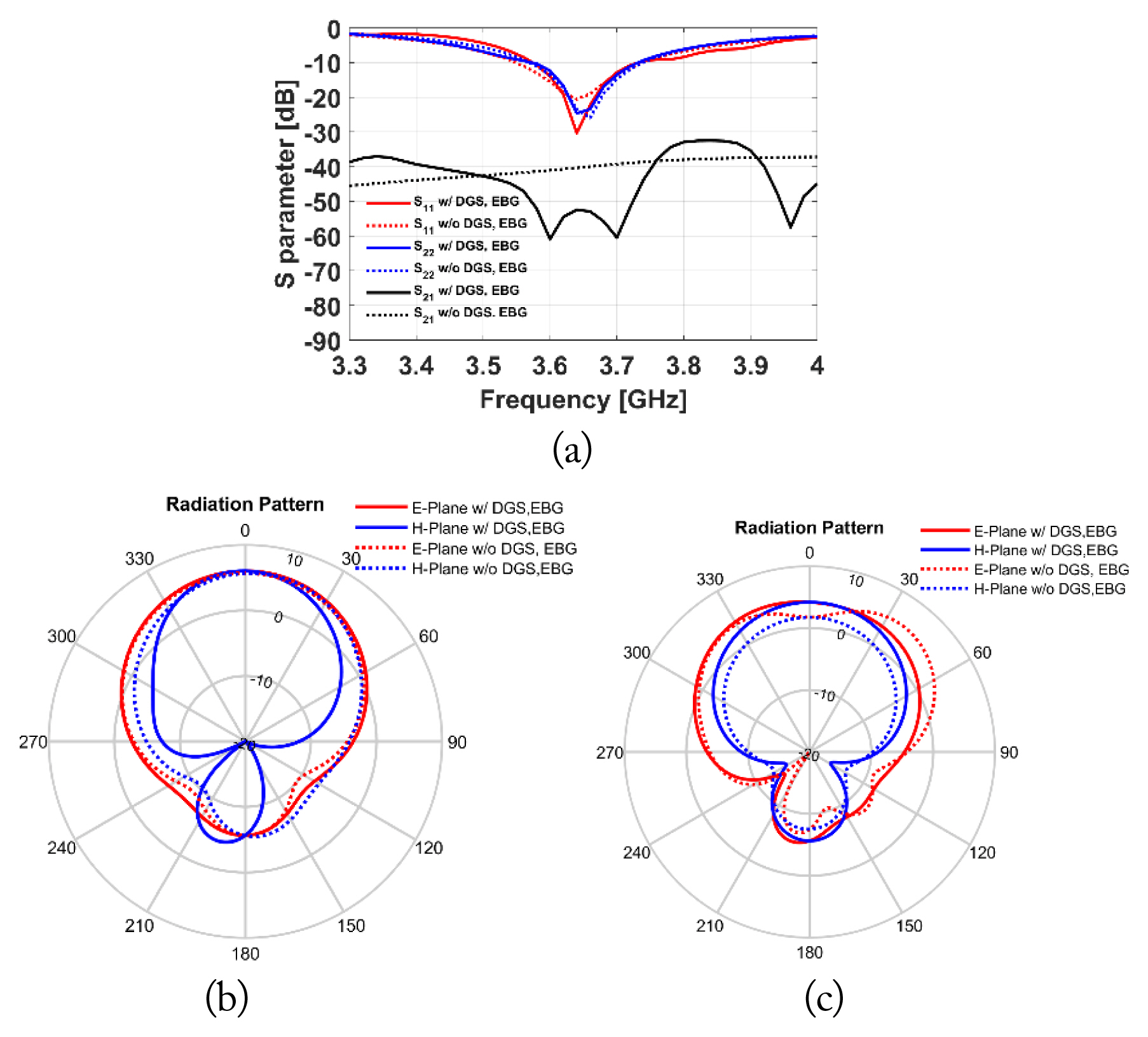
Simulation results of the repeater antenna with the novel DGS and EBG: (a) S-parameters, (b) Tx antenna radiation pattern, and (c) Rx antenna radiation pattern.
III. Fabrication and Experiment
The fabricated and experimentally assessed antenna is shown in Fig. 11. As shown in Figs. 12–14, the measurement results are fairly consistent with the simulation results. The simulated and measured S-parameters are shown in Fig. 12(a). Although the measured S11 and S22 slightly deviate from their simulated counterparts, they are both below −10 dB in the frequency range of 3.6–3.7 GHz. The isolation measurement and simulation results are quite similar. As shown in Fig. 12(b), isolation is improved by 28 dB compared to the repeater antenna without the novel DGS and EBG. As shown in Figs. 13 and 14, the measured radiation patterns of the proposed repeater antenna are also in good agreement with the simulated patterns. As shown in Fig. 14(c), the radiation pattern of the Rx antenna is significantly improved compared to the conventional repeater antenna due to the reduction in the ground mode. The measured boresight realized gains of the Tx and Rx antennas with the DGS and EBG are 5.2 dBi and 4.05 dBi, respectively.
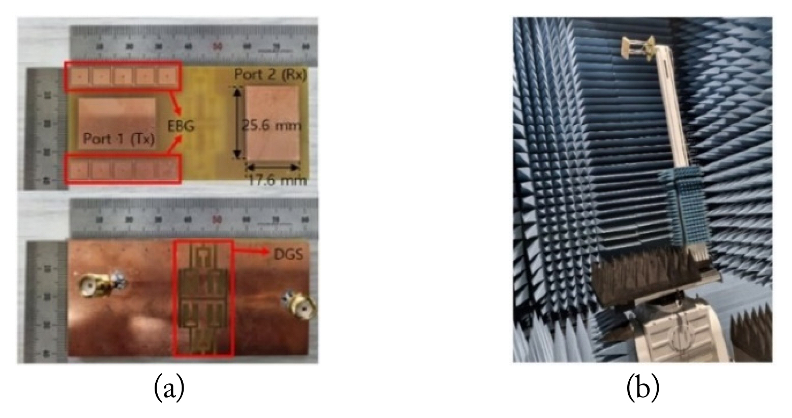
Fabrication and experimental assessment: (a) fabricated repeater antenna and (b) experimental setup.
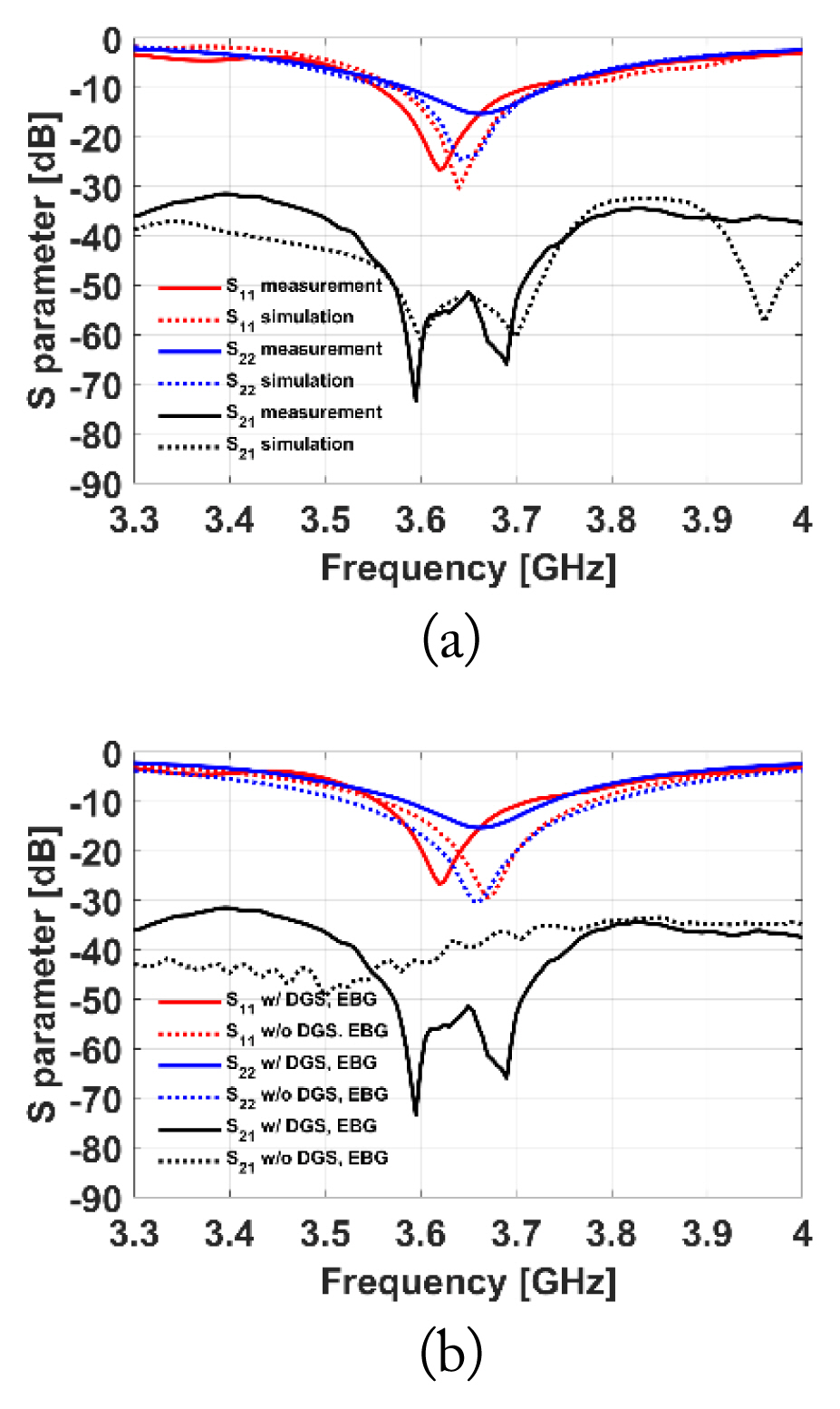
S-parameters of the proposed repeater antenna: (a) comparison between the simulated and measured S-parameters and (b) comparison of the measured S-parameters of the proposed and conventional repeater antennas.
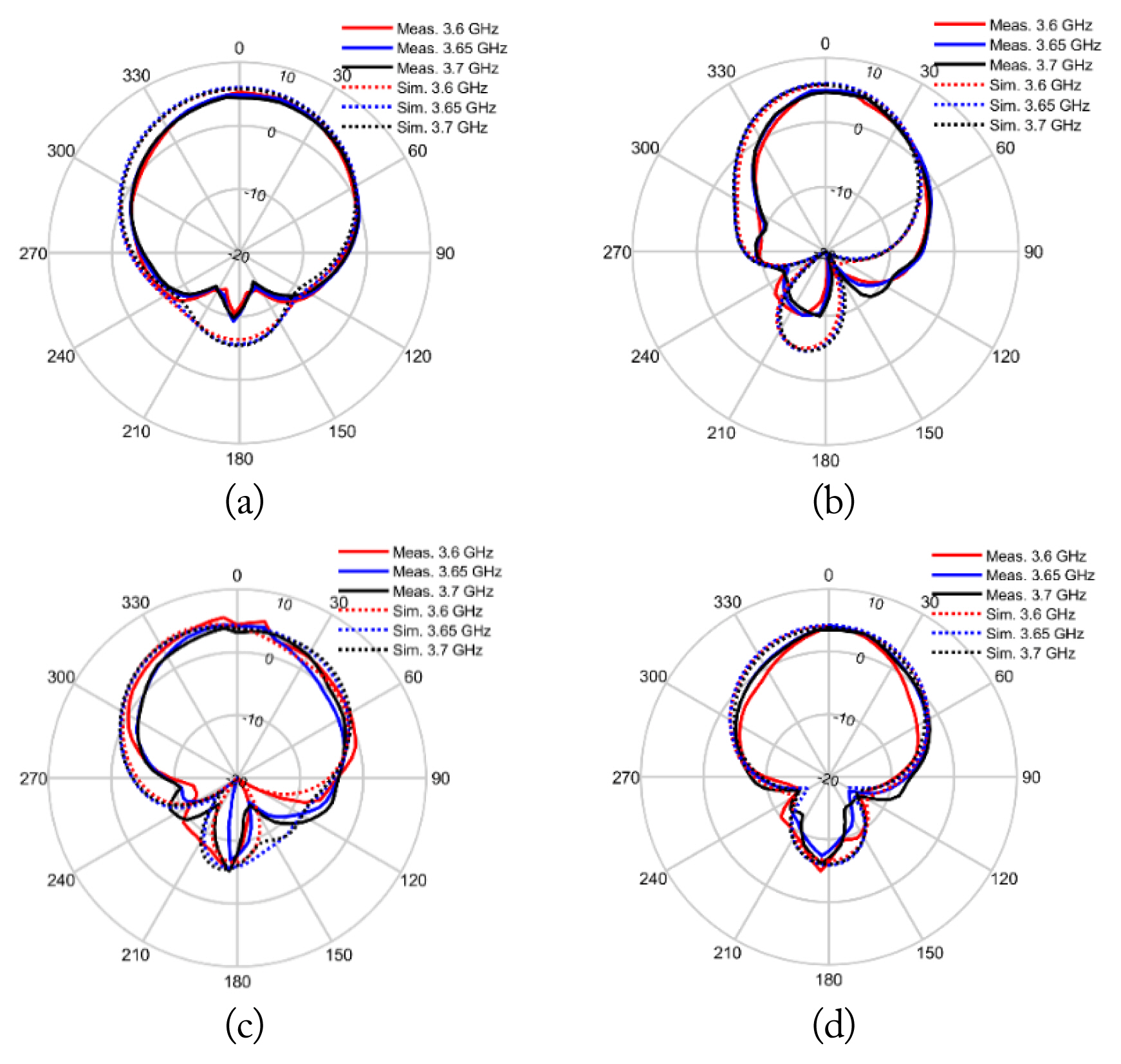
Comparison between the simulated and measured radiation patterns: (a) E-plane of the Tx antenna, (b) H-plane of the Tx antenna, (c) E-plane of the Rx antenna, and (d) H-plane of the Rx antenna.
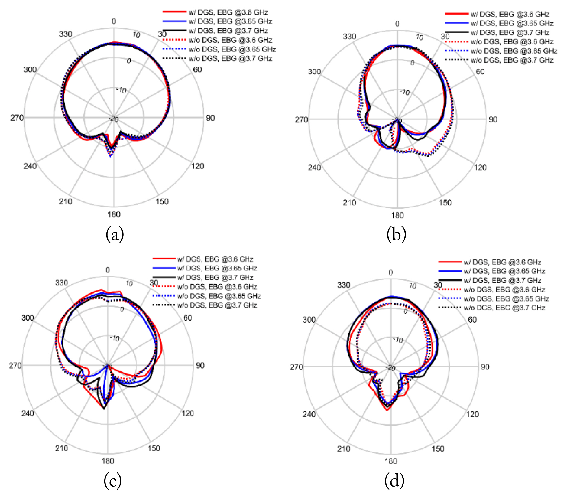
Comparison of the measured radiation patterns of the proposed and conventional repeater antennas: (a) E-plane of the Tx antenna, (b) H-plane of the Tx antenna, (c) E-plane of the Rx antenna, and (d) H-plane of the Rx antenna.
Table 1 shows a comparison between the proposed repeater antenna and previously developed antennas with high isolation. The comparison shows that the isolation of the proposed antenna is superior to that of the other antennas.

Comparison of the performance of the proposed antenna with previously developed antennas
IV. Conclusion
In this work, we propose a repeater antenna with high isolation. The proposed repeater antenna is composed of perpendicularly arranged microstrip patch antennas with a novel DGS and EBG. The size of the Tx and Rx antennas is 17.6 mm × 25.8 mm (0.21λ0 × 0.31λ0). Since the ground mode along the width of the ground plane significantly impacts the radiation pattern of the Rx antenna, the novel DGS is applied to the ground plane. This structure modifies the surface current density distribution on the ground plane, significantly reducing the deformation of the Rx antenna’s radiation pattern. To further increase the isolation between the antennas, an EBG is also used. The simulated results of the repeater antenna with the novel DGS and EBG show a significantly enhanced radiation pattern and an isolation improvement of up to 20 dB compared to a conventional antenna without the novel DGS and EBG. The experimental assessment of a fabricated repeater antenna shows a significantly reduced effect of the ground mode, which deforms the radiation pattern of the Rx antenna, and an isolation improvement of up to 28 dB.
Acknowledgments
This work was supported by the Technology Development Program (No. S2968834) funded by the Ministry of SMEs and Startups (MSS), Korea.
References
Biography

Myeong-Jun Kang received a B.S. degree from the Department of Electronic Engineering of Hanyang University, Seoul, Republic of Korea, in 2022. He is currently pursuing a Ph.D. in electronic engineering at Hanyang University. His current research interests include antenna development.

Seungyong Park received a B.S. degree from the School of Information and Communication Engineering of Chungbuk University, Cheongju, Republic of Korea, in 2016 and a Ph.D. degree in electronic engineering at Hanyang University, Seoul, Republic of Korea, in 2023. He is currently a postdoctoral researcher at Hanyang University. His current research interests include antenna development.

Kab-Goo Cho received a B.S. degree in electrical engineering from the Seoul University of Science and Technology, Seoul, Republic of Korea, in 1996 and an M.S. degree in electrical engineering from Hanyang University, Seoul, Republic of Korea, in 1998. He is currently the CEO of uqV Co. Ltd., and the head of a uqV research institute. His current research interests include wireless communication systems, antennas, artificial intelligence, and the Internet of Things.

Kyung-Young Jung received B.S. and M.S. degrees in electrical engineering from Hanyang University, Seoul, Republic of Korea, in 1996 and 1998, respectively, and a Ph.D. in electrical and computer engineering from Ohio State University, Columbus, USA, in 2008. He was a postdoctoral researcher at Ohio State University from 2008 to 2009 and an assistant professor in the Department of Electrical and Computer Engineering of Ajou University, Suwon, Republic of Korea, from 2009 to 2010. Since 2011, he has worked at Hanyang University, where he is now a professor in the Department of Electronic Engineering. His current research interests include computational electromagnetics and nano-electromagnetics.